918070/FP0811 1-1 Printed in U.S.A.
CHAPTER 1 – GENERAL
INFORMATION
INTRODUCTION
The information in this Operator’s Manual was written
to give the owner/operator assistance in preparing,
adjusting, maintaining and servicing the Compact
Excavator. More important, this manual provides an
operating plan for safe and proper use of the machine.
Major points of safe operation are detailed in Chapter 2
– Safety.
Read and understand the contents of this manual com-
pletely and become familiar with the machine before
attempting to operate it. Contact your dealer to obtain
additional manuals.
Throughout this manual, information is introduced by
the word Note or IMPORTANT. Be sure to read the
message carefully and comply with the message. Fol-
lowing this information will improve operating and
maintenance efficiency, help to avoid breakdown and
damage and extend the service life of the machine.
Do not use the machine for any application or purpose
other than described in this manual. Consult your
dealer before using special attachments or equipment
not approved for use with the machine. Any person
making unauthorized modifications is responsible for
the consequences.
The use of the machine is subject to certain hazards
that cannot be eliminated by mechanical means - only
by exercising intelligence, care, and common sense.
Such hazards include, but are not limited to: hillside
operation, overloading, instability of the load, poor
maintenance and using the equipment for purposes for
which it was not intended or designed.
It is essential to have competent and careful operators,
not physically or mentally impaired, who are thor-
oughly trained in safe operation and proper load han-
dling.
It is recommended that operators be capable of obtain-
ing a valid motor vehicle operator’s license.
Some illustrations in this manual may show doors,
guards and shields open or removed for illustrative pur-
poses only. BE SURE all doors, guards and shields are
in their proper operating positions BEFORE starting
the engine to operate the machine.
Manitou Americas, Inc. reserves the right to make
changes and improvements in the design and construc-
tion of any part without incurring the obligation to
install such changes on any unit previously delivered.
The Gehl dealer network stands ready to provide any
assistance you may require, including genuine Gehl
service parts. All service parts should be obtained from
your dealer. Give complete information about the part
and include the model and serial number of the
machine. Record the serial number in the following
space, as a handy reference.
Purchased from:______________________________
Date of Purchase: ____________________________
Model No.: _________________________________
Serial No.: __________________________________
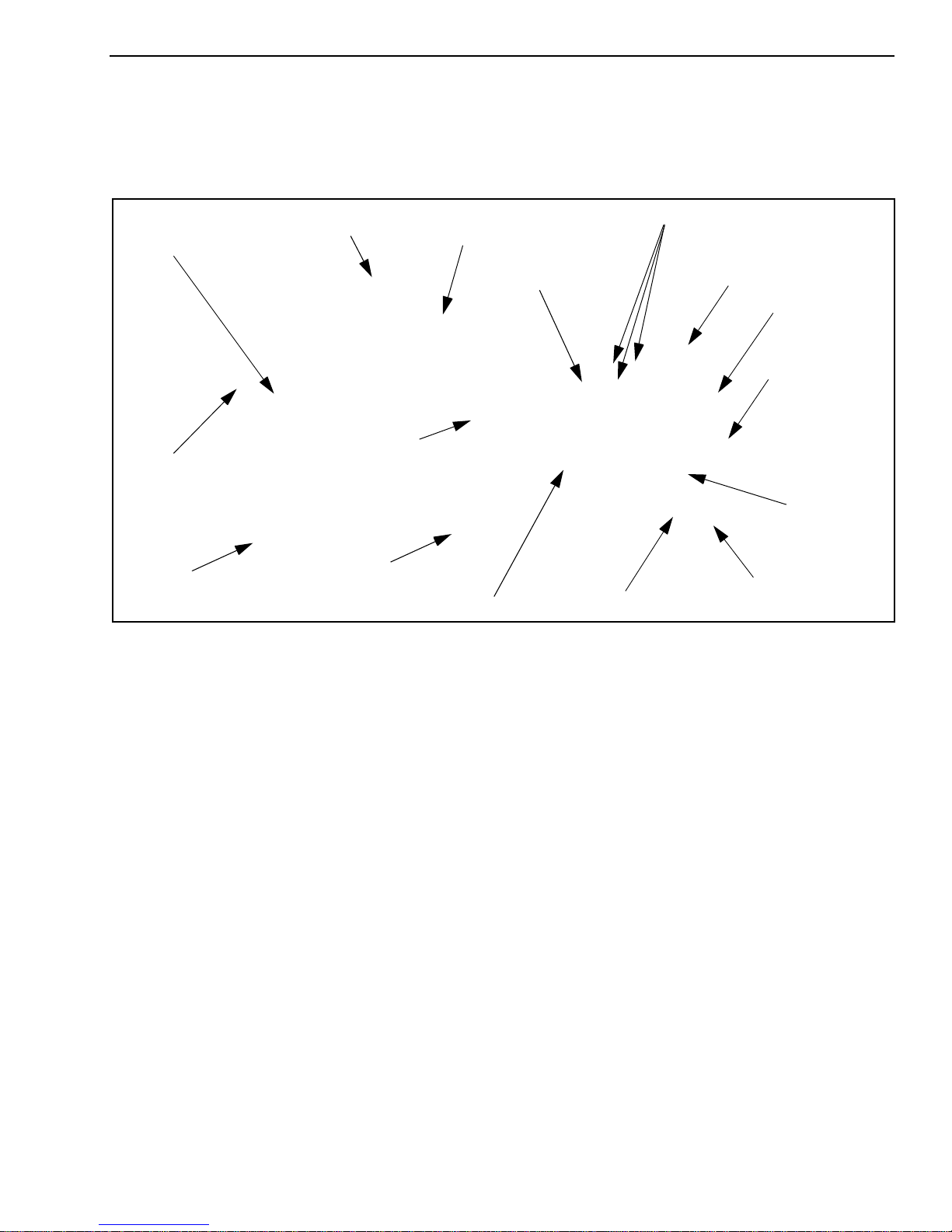
Serial Number Location
The machine serial number plate (1, Figure 1-1) is
located on the front frame, below the operator’s cab.
The cab/canopy serial number (2) is located on the right
rear of the frame next to the rear window.
Figure 1-1 Serial Number Plate Locations