IHI 17VX3 User manual

Service
Guide
17VX3
SERIAL NUMBERS
WR004001-
up
PUB. No.1
1204

HYDRAULIC MINI EXCAVATOR
-TABLE OF
CONTENTS-
SECTION 1SPECIFICATIONS
SECTION 2STRUCTURE
SECTION 3OPERATION
SECTION 4MAINTENANCE
SECTION 6PERFORMANCE STANDARDS
17VX3

SECTION 1SPECIFICATIONS
TABLE OF CONTENTS
Subject
General Specifications .
Overall Dimensions .
Working Ranges .
Weight Breakdown .
Painting Diagram .
Engine Main Date and Specifications .
Lifting Capacities Table .
Warning Signs and Labels .
Page
1 - 1 - 1
1 - 2 - 1
1 - 3 - 1
1 - 4 - 1
1 - 5 - 1
1 - 6 - 1
1 - 7 - 1
1 - 8 - 1
17VX3

SPECIFICATIONS
GENERAL SPECIFICATIONS
•
BASE
MACHINE PERFORMANCE
Swing speed min-19.5
Travel speed
km
/ h
2.1
/4.0
Gradability
0/0
(deg.) 58 (30)
•ENGINE
Engine model -YANMAR 3TNV70
4cycle, water cooled,
Engine type over-head, valve,
indirect injection
No.
of
cyl.- bore xstroke mm 3-70 x74
Total piston displacement L0.854
kW
/min-1
10.5/2300
Rated output [DIN6271, 10.4 /2300]
Max. torque
Nem
/min-1
51.8/1600
•WEIGHT
STD with ADD
Weight
Machine mass Rubber shoe
kg
1220 1320
Steel shoe 1280 1380
Average ground bearing Rubber shoe kPa 26.2 27.8
pressure Steel shoe 27.8 29.4
•
AMOUNT
OF FUEL, OIL,
COOLANT
Fuel L20
Hydraulic Oil level L19
fluid Total amount L23
Max. level L3.8
Engine oil Min. level L
2.1
Engine proper L0.9
Coolant Total amount L3.6
1 - 1 - 1
17VX3

•BUCKET
SPECIFICATIONS
17VX3
@: Std. applicable
0:
Applicable
X:
Not applicable
Bucket capacity Side Number Combinations
ISO(m3)cutter
of
Weight Remarks Remarks
width Std. Long
(mm) teeth (kg)
Heaped Struck arm arm
0.044 0.025 450 347 @XStandard General digging
0.024 0.015 300 235 00OPT. Ditch digging
0.033 0.018 350 3
41
0@OPT. Long arm
Ditch digging
0.055 0.029 500 349 0XOPT. Loading
1 - 1 - 2

SPECIFICATIONS
OVERALL DIMENSIONS
MF
17VX3
K
z
L
Unit: mm
STD ADD
Weight
Codes Description Rubber shoe Steel shoe Rubber shoe Steel shoe
ACrawler shoe width 230 230 230 230
BOverall length
of
crawler 1570 1540 1570 1540
COverall width
of
crawler 960-1280 960-1280 960-1280 960-1280
DCanopy 980 980 980 980
ECanopy 2330 2330 2330 2330
FRear end swing radius 650 650 720 720
GRear end ground clearance 460 460 460 460
HMini. ground clearance
175 175 175 175
IOverall length
of
undercarriage 1930 1930 1930 1930
JBlade height 235 235 235 235
KBlade width 960 960 960 960
LOverall length Blade
in
front 3380 3380 3380 3380
Blade
in
rear 3750 3750 3750 3750
MFront end mini. radius
at
center 1490 1490 1490 1490
NArm head clearance 2630 2630 2630 2630
1 - 2 - 1

C)
~
co
L.D
c.o
C)
L.D
c.o
(Y)
co
SPECIFICATIONS
WORKING RANGE
•BOOM SWING DIGGING WORKING RANGE
®R1270
Front-end min radius
(at left boom swing)
(6)
R1280
Front-end min radius
(at right boom swing)
1 - 3 - 1
1090
1100
650
17VX3

SPECIFICATIONS
17VX3
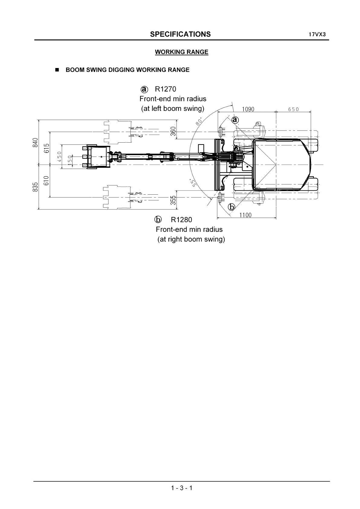
•WORKING RANGE (BACK HOE) F
II
/
II
/
J
H
~
o
\
)
fE--------+--------'"!I
/
/
/
/
\\
""
Long
arm
Std.
arm
""
\
\\
\\
/
/
/
I
/
I
I
/
I
I
II
\
w
u
L
N
B
A
Unit: mm
Key Description Std. arm Long arm
Std.
of
bucket capacity (m3
),
ISO Heaped 0.044 0.033
AMax. digging radius 3760 3990
BMax. bucket outreach at ground level 3660 3910
CMax. digging depth(Not used blade) 2100 2350
DRadius
of
max. digging depth 1680 1680
EMax. digging height 3610 3810
FRadius
of
max. digging height 1740 1900
GMax. dumping height 2560 2760
HRadius
of
max. dumping height 1610 1770
IMin. dumping height 950 720
JRadius
of
min. dumping height 1350 1440
KMax. vertical digging depth 1770 2010
LRadius
of
max. vertical digging depth 2430 2490
MRadius
of
min. digging ground level 1220 1120
NMax. clean-up radius at floor level 2810 3040
1 - 3 - 2

WEIGHT BREAKDOWN
1.
Machine weight at transported style
SPECIFICATIONS
WEIGHT BREAKDOWN
17VX3
2.
Base machine
3.
Upper structure
4.
Under carriage
5.
Hoe attachment
Shoe /Cabin Spec. Weight (kg)
Rubber shoe /Canopy 4P 1550
Steel shoe/Canopy 4P 1620
(With ADD CWT +100 kg)
Shoe /Cabin Spec. Weight (kg)
Rubber shoe /Canopy 4P 1360
Steel shoe/Canopy 4P 1430
(With ADD CWT +100 kg)
This weight
is
not the mass
of
the
machine body. It includes the weight
of
water, fuel, blade and others.
Specification Weight (kg)
Canopy 4P 830
(With ADD CWT +100 kg)
Specification Weight (kg)
Rubber shoe 530
Steel shoe 600
Specification Weight (kg)
Standard arm 190
Long arm 200
1 - 4 - 1

SPECIFICATIONS
PAINTING DIAGRAM
17VX3
A
B
A
B
B
B B
B
A
B
Color
code
for
IHI Standard
Color
Code AB
Name
Light
green Dark
gray
Munsell No. 2.5BG 6/10 N - 3.0
Notes:
1 ) Do
not
coat
rubber,
sponges,
catch
metal
fixtures,
hydraulic
hoses,
cylinder
rods, rod
packing,
air
cleaners,
mufflers
with
paint.
2 ) Do
not
coat
operating
lever,
side
box, gauges, pedal, handrail,
seat
or
undercover
with
paint
because each
of
them
have
already
been painted as a
single
unit.
1 - 5 - 1

SPECIFICATIONS
ENGINE MAIN DATE AND SPECIFICATIONS
17VX3
Engine model Y
AN
MAR 3TNV70-QIK
Applicable emission control EPA Tier2
Engine type Vertical serial water-cooled 4-cycle diesel engine (indirect injection)
No.
of
cylinder -bore xstroke
3-<p70x74
Total piston displacement 0.854L
Compression ratio 23
Output (Net, Output tolerance: ±3%)10.5kW /2300min-1
(Machine name plate indication: 10.5 kW/2300rpm)
Maximum torque 47.5",51.8Nem/1600 ±100 min-1
Fuel consumption
~279g/kWeh
Atmospheric conditions Room temperature 25°C Atmospheric pressure 100kPa (750mmHg)
Relative humidity 30%
Fuel oil condition Diesel oil-ISO 8217 DMA,
BS
2869
A1
or A2 (Cetane No.45 min.)
Non-loaded rotation speed
Maximum;
2460(+25/-25)min-1,
Minimum;
1250(+25/-25)min-1
Speed fluctuation Momentary ;
~
12
%,Stabilized ;
~
7%
Stabilization time
~6s
Rotation fluctuation
~30min-l
Permissible tilt angle Continuously 30 degrees (longitudinal and cross) Momentary 35
degrees (longitudinal and cross)
Engine rotating direction Counterclockwise when viewed from the flywheel side
Engine weight (Dry) 98 (+5/0)kg
Fuel system
Applicable fuel Diesel oil-ISO 8217 DMA,
BS
2869
A1
or A2 (Cetane No.45 min.)
Fuel injection pump Bosch YPES type (YPES-ML) unitized with the reduction gear
Filtering system Full flow filter paper
Governor Centrifugal all-speed type
Lubrication system
Applicable lubricant Class CD 10W30
in
new SAE classification
Lubrication pump Trochoid pump
Lubrication system Forced lubrication
Cooling system
Cooling system Radiator cooling
Radiator Pressurized and fully closed
Fan <p290-5(suction), Seat between fans T=18
Crank pulley/fan pulley =
<p
110/90
IAir cleaner ICyclone type (resin 4inches) double element
Start system Electrical
Starter 12V-1.1kW
Alternator 12V-20A
Battery (recommended value) 55B24
Auxiliary unit for start Glow plug (super-quick glow plug)
Stop unit Stop solenoid from Syncho Start, buit-in governor,
12
V(waterproof)
Coolant capacity Engine 0.9L (engine proper)
Lubricant volume Total: 3.8L, Effective: 1.7L (oil pan)
1 - 6 - 1

SPECIFICATIONS
LIFTING CAPACITIES TABLES
LOAD RATING
CHART
(SAE method)
Note:
At
front over end and the Blade fulcrum with equipped standard arm.
Rated loads do not exceed
87%
of
hydraulic capacity or
75%
stability.
Unit:
ton
+ : Lifting height
* :Maximum lifting radius
17VX3
4
3
Position
of
normal lifting (+)
.-.
E
I
2
1
o
0.3
*+1
0.3+
································
·0.3 .
0.3
!
*+
+
0.3 0.3
++
0.3
0.3
.............................................
++
0.3
Oj4
++
0.3
0:4
+ +
0.3
0.3
+
0.3
++
0.4 0.5
++
0.5
9.7
++
0.5
0.8
Position
of
max lifting
(*)
++
03 04
+
0.5
+
0.7
1+
+++
- 1 I
Q·;?
9:4 9:§
Q:?...........................
. .
2
Lifting Radius (R m)
-2
43
++
Q.3 Q.3
+
0.5
1o
1 - 7 - 1
-3.3
3.3
3.3
6.6
-6.6
6.6
9.9
9.9
13.1
13.1
lbs.
ft
ft
660
660
660
660
660
660
660
660
660
660
660
660
660
660
660
660
660
660
660
660
660
660
880
880
880
880
880
1100
1100
1540
1100
1100
1540
1100
1320
1760
1760

SPECIFICATIONS
17VX3
LIFTING CAPACITIES TABLES
LOAD RATING CHART (SAE method)
Note:
At over side; at crawler width contraction; with equipped standard arm.
Rated loads do not exceed
87%
of
hydraulic capacity or
75%
stability.
Unit:
ton
+ : Lifting height
* :Maximum lifting radius
4Position
of
normal lifting
(+)
Position
of
max lifting
(*)
...........................................
HR--.....
~l%.."""",,"~~'&..~\.~
+
0.2
++
0.1
0.2
+
0.1
++
0.1
0.2
..........................................
++
0.1
°r
2
++
0.1
0.2
++
0.1
0.1
+++
0.1
0.2
0.3
+
q.1
++
0.1 0.1
+
0.1
0.1
*+1
0.1
+
·
..
···································0.1
.
0.1
i
*+
+
0.1 0.1
0.1
*++
0.1
0.1
.............................................
++
01 01
1+
......................................................................
I
Q~.1
.
0.1
*+
0.2
3 .
0.1
*+
0.1
o
-1
..-. 2
E
I
+-'
..c
0>
·m
I
0>
1
c
~
:.::J
2
Lifting Radius (R m)
-2
43
++
01
0.2
+
0.3
1o
1 - 7 - 2
-3.3
3.3
3.3
lbs.
9.9
9.9
ft
ft
220
220
220
220
220
220
220
220
220
220
220
220
220
220
220
220
220
220
220
220
220
220
220
220
220
220
220
220
440
440
440
440
440
440
660
660
440
440
13.1
13.1
6.6
6.6

SPECIFICATIONS
17VX3
LIFTING CAPACITIES TABLES
LOAD RATING
CHART
(SAE method)
Note:
At
over side;
at
crawler width expension; with equipped standard arm.
Rated loads do not exceed
87%
of
hydraulic capacity
or
75%
stability.
Unit:
ton
+ : Lifting height
'*
:Maximum lifting radius
4Position
of
;normallifting (+)
Position
of
max
lifting
('*)
+
0.2
++
0.2
0.3
++
0.2
0.3
++
0.2
0.3
++
0.1
0.2
++
0.1
0.2
0.1
'*+!
+ +
0.2+
0.2
0.2
·
..
··································0.2
.
0.1
.
'*+
++
0.1
0.2 0.2
0.1
'* ++++
01
0[2
O.2@
H
R--.
~l\.~~"",,~~'&-.~'@
3 .
0,2
*+
0.2
0.2
'*
+
0.3
o++
0.1
0.2
i+
+++
- 1
I.Q,?.....9:?
~
.9:?.................................... .
+++
0.2
0.3 0.4
..-.
2
E
I
"""-'
.........,
..c
0>
'Q)
I
0>
1
c
~
:.:J
-2
43 2
Lifting Radius (R m) o
1 - 7 - 3
13.1
13.1
9.9
9.9
6.6
-6.6
6.6
3.3
3.3
-3.3
lbs.
ft
ft
440
440
440
440
440
440
440
440
440
440
440
440
440
440
440
440
440
440
440
440
440
220
220
220
220
220
220
220
220
660
660
660
660
660
660
660
1100
880

SPECIFICATIONS
17VX3
LIFTING CAPACITIES TABLES
LOAD RATING CHART (SAE method)
Note:
ADD. CWT specification
At
front over end and the blade fulcrum with equipped standard arm.
Rated loads do not exceed
87%
of
hydraulic capacity or
75%
stability.
Unit:
ton
+ : Lifting height
'*
:Maximum lifting radius
4Position of
normal lifting
(+)
0.3
'*
+
3
0.3
..
0.3
"*
+ +
0.3
0.3
Position of
max lifting
('*)
0.3
'*
+~
+ +
.............................
0,3
+
0.3
0.3
0.3
0.3
'*+
++
0.3
0.3 0.3
++++1
.........
0.3
q.3
0.4 0.5
H
R--'
++++1
0.3 0.4
0.5
q::::::
..7,
£,,""""""~""""~'\..,,"'''''~
++++
0.3-r-0.5_~8
o
2
..-.
E
I
"""-"
+-'
..c
0>
·m
I1
0>
C
£
:.::i
++
03
Q4 +
0.5
+
0.7
!+ + ++
- 1
~
0.3
0.4 0.6
0.8
;
"'1
++
03
0.3
+
0.5
-2
43 2
Lifting Radius (R m) 1o
1-7-4
13.1
13.1
3.3
-3.3
3.3
lbs.
ft
ft
6.6
6.6
-6.6
9.9
9.9
660
660
660
660
660
660
660
660
660
660
660
660
660
660
660
660
660
660
660
660
660
660
660
1100
880
880
880
880
880
1100
1100
1100
1100
1760
1540
1540
1760
1320

SPECIFICATIONS
17VX3
LIFTING CAPACITIES TABLE
LOAD RATING CHART (SAE method)
Note:
ADD.
CWT
specification
At
over
side;
at crawler width contraction; with equipped standard arm.
Rated loads do not exceed
87%
of
hydraulic capacity
or
75%
stability.
Unit:
ton
+ : Lifting height
* :Maximum lifting radius
4
0.2
*
3 .
0.1
*+ +
0.1
0.2
++++
..........
0.1
0.1
0.2
0.2
Position
of
max lifting
(*)
J
...............................................................................
H
R---.
l,,~~~~~'*'''&~
+
~.2
+
0.1
+
0.2
+
0.1
+
0.1
0.1
:
*+1
+ +
..............................
0.1
+
0.2 0.2
0.1
0.1
*+
+
0.1 0.1
2
.-.
E
I
+-'
..c
0)
·CD
I1
0)
c
iE
:.::i
o++++
1-----
0.1
-
0.1
-
0.1
-
0.2
--------!-----------!
++
01 01
1+
-1
i
0.1
++
01
~.2
+++
o
1m
0.2
m.m
03m.........
. .
+++
0.2
0.2
0.3
-2
43 2
Lifting Radius (R m) 1o
1 - 7 - 5
-3.3
9.9
13.1
3.3
6.6
-6.6
6.6
9.9
13.1
lbs.
ft
ft
220
220
220
220
220
220
220
220
220
220
220
220
220
220
220
220
220
220
220
220
220
440
440
440
440
440
440
440
440
440
440
440
440
440
660
660
660

SPECIFICATIONS
17VX3
LIFTING CAPACITIES TABLE
LOAD RATING CHART (SAE method)
Note:
ADD. CWT specification
At over side; at crawler width expension; with equipped standard arm.
Rated loads do not exceed
87%
of hydraulic capacity or
75%
stability.
Unit:
ton
+ : Lifting height
'*
:Maximum lifting radius
4
0.3
'*
3
..
0.2
'*
+ +
0.2
0.2
++++
.........
0.2
0:.2
0.3
0.4
.
0.1
'*+
+
0.2
0.2
Position
of
max lifting
('*)
+
0.4
+
0.3
+
0.3
+ +
....
0.2
0.2
+
0.2
+
0.1
0.2
'*
+~
.............................
0
..
2+
0.2
2
..-.
E
I
.........
..c
.Q>
Q)
I1
0>
C
~
:.:J
++++
o
0.2
-
0.2
-
0.3
-
0.4
--------i---------I
++
0.2
0.2
+
0.2
+
0.4
1+ +++ :
- 1
~
0.2
0.2
0.4 0.6
~
..
+++
0.2
0.3
Q.4
-2
4 3 2
Lifting Radius (R m) 1o
1 - 7 - 6
lbs.
440
440
440
440
440
440
440
440
440
440
440
440
440
440
440
440
440
440
440
440
440
220
660
880
13.1
1320
220
660
660
9.9
6.6
660
660
660
660
880
880
880
880
880
13.1
9.9
6.6
3.3
3.3
-3.3
-6.6
ft
ft

SPECIFICATIONS
WARNING SIGNS AND LABELS
17VX3
There are several specific safety signs
on
your machine. Their exact location and description of the
hazard are reviewed
in
this section.
Please take the time to familiarize yourself with these safety signs.
Wake sure that you can read all safety signs. Clean or replace these if you cannot read the words or see
the pictures. When cleaning the labels use acloth, water and soap.
Do
not use solvent, gasolin, etc.
You must replace alabel if it
is
damaged, missing or cannot
be
read. If alabel
is
on
apart that
is
replaced, make sure anew label
is
installed
on
the replaced part.
See you IHI dealer new labels.
Located warning levels
1 - 8 - 1

Illustrated
symbol Recommended
explanation
SPECIFICATIONS
Illustrated
symbol
17VX3
Recommended
explanation
CD
w
Read manual before
operation, maintenance,
disassembly, assembly
and transportation.
•Part No.: 0405 359 00
Sign indicates ahazard of being
crushed or
run
over by
unexpected moving of stopped
machine.
Lower working device to lock
position and remove engine key
with you before leaving
machine.
•Part No.: 0405 508 00
@
1&
•
D++I
Sign indicates
an
electrocution hazard if
machine
is
brought too
near electric power lines.
Keep asafe distance
from electric power lines.
•Part No.: 0405 506 00
Sign indicates ahazard of
being hit
by
the working
device of the machine.
Keep away from machine
during operation.
•Part No.: 0405 668 00
Sign indicates acrush hazard
by
rotation of upper
structure of the machine.
Keep away from swing area of machine.
•Part No.: 0406 269 00
@
~
~~
~
0
~
~~
~@~
040567400
Sign indicates ahazard of rotating parts, such as belt.
Turn off before inspection and maintenance.
•Part No.: 0405 674 00
Sign indicates ahazard of rotating parts, such
as fan.
Turn off before inspection and maintenance.
•Part No.: 0405 675 00
@
00
not put your hand
in
the machine.
Otherwise, you might get your hand caught
in
it.
•Part No.: 0406 262 00
1 - 8 - 2

Illustrated
symbol Recommended
explanation
SPECIFICATIONS
Illustrated
symbol Recommended
explanation
17VX3
I~W
Sign indicates
an
electrical hazard from handing
the cable.
Read manual for safe and proper handing.
•Part No.: 0405 504 00
I~IW
Sign indicates ahazard of flying plug from
track adjuster that could cause injury. Read
manual before adjusting track for safe and
proper handling.
•Part No.: 0405 505 00
Sign indicates aburn hazard from spurting
hot water or oil if radiator or hydraulic tank
is
uncapped while hot.
Allow radiator or hydraulic tank to cool before
removing cap.
•Part No.: 0405 503 00
DO
NOT
OPERATE
@DENGER!
Attach a
00
NOT OPERATE warning tag to start switch or controls
before servicing or repairing the machine.
00
not start the engine or move any of the controls if there
is
00
NOT OPERATE or similar warning tag attached to the start
switch or controls.
Keep
in
the tool box do not use warning tag.
•Part No.: 0405 323 00
1 - 8 - 3
Table of contents
Other IHI Compact Excavator manuals