CARVIN ENGINEERING DATA CARVIN ENGINEERING DATALT Amplier Series
PG 6
Set Up
LT Amplifier Series 2022-3-29
carvinaudio.com
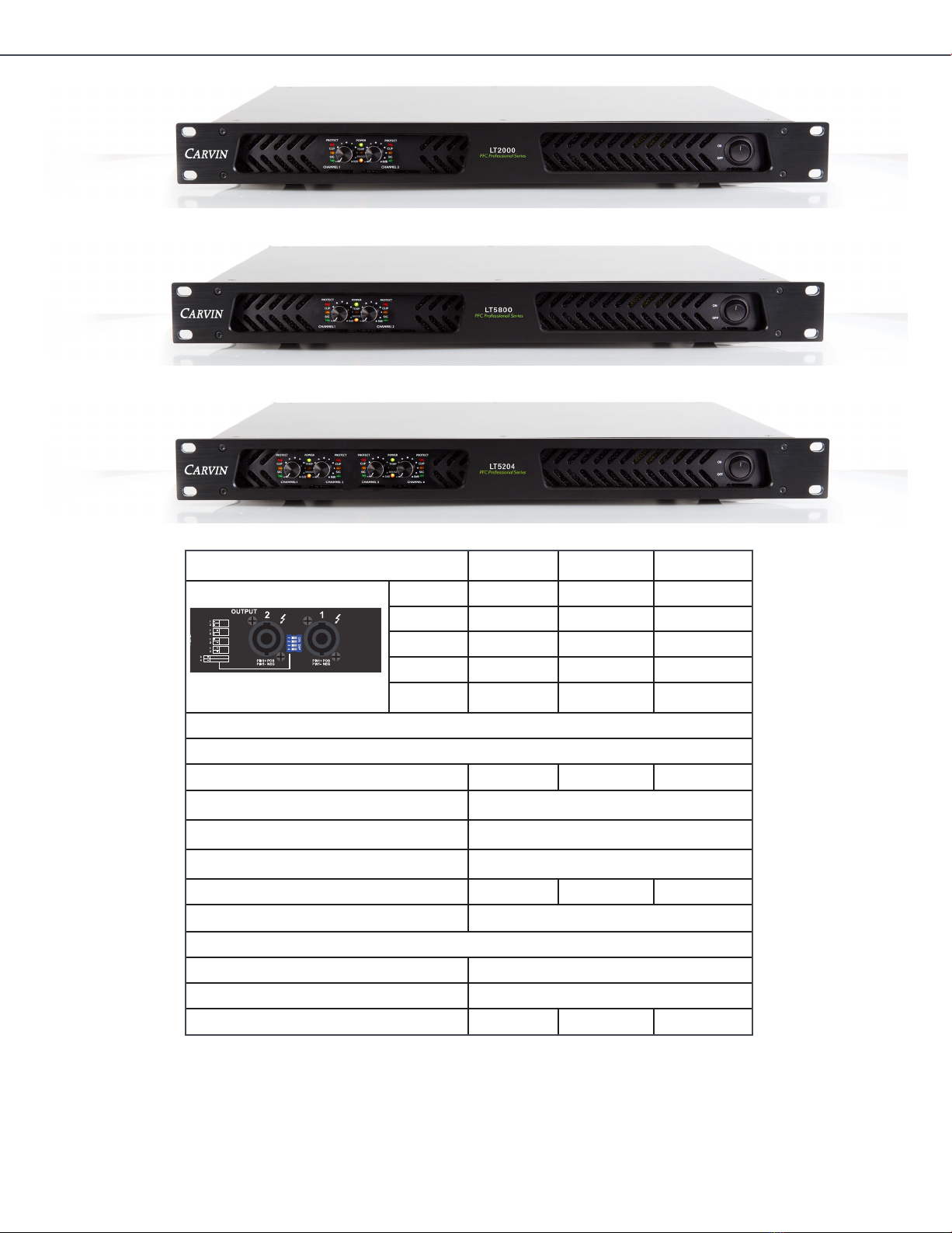
PFC Professional Series
PROTECT POWER
TEMP
CLIP
SIG
CLIP
SIG
CHANNEL CHANNEL 2
PROTECT
BRIDGE
ON
OFF
PFC Professional Series
OHM 101W/CH - 3380W x 1CH BRIDGE
4 OHM 1690W/CH - 5760W x 1CH BRIDGE
2 OHM 2880W/CH
BRIDGE CH + = POS = NEG
0dB
-3dB
-6dB
-10dB
INPUT SENSITIVITY
MONO/BRDG
LIMITER OFF
14.56 “
370mm
19.00 “
483mm
1.73 “
44mm
ASSEMBLED IN PRC
100-240VAC 50-60Hz
PFC Professional Series
PROTECT POWER
TEMP
CLIP
SIG
CLIP
SIG
CHANNEL CHANNEL 2
PROTECT
BRIDGE
ON
OFF
PFC Professional Series
BRIDGE CH + = POS = NEG
BRIDGE CH + = POS = NEG
PFC Professional Series
TEMP
CLIP
SIG
CLIP
SIG
CHANNEL 3CHANNEL 4
PROTECT PROTECTPROTECT POWER
TEMP
CLIP
SIG
CLIP
SIG
CHANNEL CHANNEL 2
PROTECT
BRIDGE BRIDGE
PFC Professional Series
OHM 34W/CH - 1180W x 1CH BRIDGE
4 OHM 580W/CH - 2010W x 1CH BRIDGE
2 OHM 1010W/CH
BRIDGE CH + = POS ; = NEG
PFC Professional Series
PROTECT POWER
TEMP
CLIP
SIG
CLIP
SIG
CHANNEL CHANNEL 2
PROTECT
BRIDGE
ON
OFF
ON
OFF
+2dBu
+4dBu
+8dBu
+12dBu
INPUT SENSITIVITY
MONO/BRDG
LIMITER OFF
PFC Professional Series
BRIDGE CH + = POS = NEG
100-240VAC 50-60Hz
100-240VAC 50-60Hz
100-240VAC 50-60Hz
+2dBu
+4dBu
+8dBu
+12dBu
INPUT SENSITIVITY
MONO/BRDG
LIMITER OFF
+2dBu
+4dBu
+8dBu
+12dBu
INPUT SENSITIVITY
MONO/BRDG
LIMITER OFF
+2dBu
+4dBu
+8dBu
+12dBu
INPUT SENSITIVITY
MONO/BRDG
LIMITER OFF
OHM W/CH - W x CH BRIDGE
4 OHM W/CH - W x CH BRIDGE
2 OHM W/C H
OHM W/CH - W x CH BRIDGE
OHM W/CH - W x CH BRIDGE
OHM W/C H
6 7 85432 9
1411 1210
1
1513
LT SERIES OPERATION
»1. MOUNTING
are normally used to secure the amp to the front and rear of the gear rack. All
»2. BRIDGE MODE
can be run with both channel pairs in bridge mode giving you two high
of channels in bridge mode and the other pair of channels in stereo, giving
speaker connectors may be used at the same time when in bridge mode! Use
»3. TEMP
operating temperature exceeds the safe operating limit of the amplifier and
the temperature protection is activated. When activated, the power output of
the amplifier is reduced, allowing the internal amplifier temperature to return
to the safe operating range while still producing audio. The TEMP LED
air is restricted,
hot air to escape, or
»4. POWER
powered up.
»5. CHANNEL LEVEL CONTROL
reducing the headroom of the signal source, the level controls should be
turned full on.
»6. PROTECT
draws excessive current or a direct short is detected caused by a shorted
speaker cable or speaker system. Reset this condition by turning the amp off
for two seconds and then on again. Check for shorted cables and that the
»7. CLIP
its maximum clean output. Occasional flashing caused by low frequency
peaks are normal and will not harm speakers capable of handling
damage to the amp.
»8. SIGNAL
the channel.
»9. POWER ON/OFF
making sure the rear plug is fully inserted before engaging the power switch.
»10. AC POWER
use outside of North American will need to replace the EDISON plug with the
back the latch on top of the connector with your thumb and twist the
the amp will require service. Each amp will require a dedicated
circuit breaker for the amp to achieve its full output
»11. SPEAKER OUTPUT
applications. Secure the Twist-Lock cable connection by turning to the
right to the lock position. Twist-Lock outputs are compatible with standard
70V/100V DISTRIBUTION SYSTEM
divide the total wattage of all the speaker settings by the output of the amp
is the reduction of the wire size to drive a number of speakers.
12. SENSITIVITY / AMPLIFIER MODES
input signal is required to achieve full power output from the amplifier. The
becomes. To change the sensitivity, move the dip
on the diagram.
limiter automatically reduces the signal to prevent
hard clipping, which helps protects the drivers. It is
recommended to keep the limiter ON. To turn the limiter
»13. COOLING FANS
cold air from the front panel and exhaust the heat from the
wall when using for high powered applications. Inadequate ventilation will
activate the thermal protection prematurely. The front cooling vents are not to
be restricted.
»14 & 15 CHANNEL INPUTS
PFC Professional Series
PROTECT POWER
TEMP
CLIP
SIG
CLIP
SIG
CHANNEL CHANNEL 2
PROTECT
BRIDGE
ON
OFF
PFC Professional Series
BRIDGE CH + = POS = NEG
BRIDGE CH + = POS = NEG
PFC Professional Series
TEMP
CLIP
SIG
CLIP
SIG
CHANNEL 3CHANNEL 4
PROTECT PROTECTPROTECT POWER
TEMP
CLIP
SIG
CLIP
SIG
CHANNEL CHANNEL 2
PROTECT
BRIDGE BRIDGE
PFC Professional Series
OHM 34W/CH - 1180W x 1CH BRIDGE
4 OHM 580W/CH - 2010W x 1CH BRIDGE
2 OHM 1010W/CH
BRIDGE CH + = POS ; = NEG
PFC Professional Series
PROTECT POWER
TEMP
CLIP
SIG
CLIP
SIG
CHANNEL CHANNEL 2
PROTECT
BRIDGE
ON
OFF
ON
OFF
+2dBu
+4dBu
+8dBu
+12dBu
INPUT SENSITIVITY
MONO/BRDG
LIMITER OFF
PFC Professional Series
BRIDGE CH + = POS = NEG
100-240VAC 50-60Hz
100-240VAC 50-60Hz
100-240VAC 50-60Hz
+2dBu
+4dBu
+8dBu
+12dBu
INPUT SENSITIVITY
MONO/BRDG
LIMITER OFF
+2dBu
+4dBu
+8dBu
+12dBu
INPUT SENSITIVITY
MONO/BRDG
LIMITER OFF
+2dBu
+4dBu
+8dBu
+12dBu
INPUT SENSITIVITY
MONO/BRDG
LIMITER OFF
OHM W/CH - W x CH BRIDGE
4 OHM W/CH - W x CH BRIDGE
2 OHM W/CH
OHM W/CH - W x CH BRIDGE
OHM W/CH - W x CH BRIDGE
OHM W/CH
PFC Professional Series
PROTECT POWER
TEMP
CLIP
SIG
CLIP
SIG
CHANNEL CHANNEL 2
PROTECT
BRIDGE
ON
OFF
PFC Professional Series
BRIDGE CH + = POS = NEG
BRIDGE CH + = POS = NEG
PFC Professional Series
TEMP
CLIP
SIG
CLIP
SIG
CHANNEL 3CHANNEL 4
PROTECT PROTECTPROTECT POWER
TEMP
CLIP
SIG
CLIP
SIG
CHANNEL CHANNEL 2
PROTECT
BRIDGE BRIDGE
PFC Professional Series
OHM 34W/CH - 1180W x 1CH BRIDGE
4 OHM 580W/CH - 2010W x 1CH BRIDGE
2 OHM 1010W/CH
BRIDGE CH + = POS ; = NEG
PFC Professional Series
PROTECT POWER
TEMP
CLIP
SIG
CLIP
SIG
CHANNEL CHANNEL 2
PROTECT
BRIDGE
ON
OFF
ON
OFF
+2dBu
+4dBu
+8dBu
+12dBu
INPUT SENSITIVITY
MONO/BRDG
LIMITER OFF
PFC Professional Series
BRIDGE CH + = POS = NEG
100-240VAC 50-60Hz
100-240VAC 50-60Hz
100-240VAC 50-60Hz
+2dBu
+4dBu
+8dBu
+12dBu
INPUT SENSITIVITY
MONO/BRDG
LIMITER OFF
+2dBu
+4dBu
+8dBu
+12dBu
INPUT SENSITIVITY
MONO/BRDG
LIMITER OFF
+2dBu
+4dBu
+8dBu
+12dBu
INPUT SENSITIVITY
MONO/BRDG
LIMITER OFF
OHM W/CH - W x CH BRIDGE
4 OHM W/CH - W x CH BRIDGE
2 OHM W/CH
OHM W/CH - W x CH BRIDGE
OHM W/CH - W x CH BRIDGE
OHM W/CH
PFCProfessionalSeries
PFCProfessionalSeries
PFCProfessionalSeries
PFCProfessionalSeries
PFCProfessionalSeries
PFCProfessionalSeries
PFCProfessionalSeries
PFCProfessionalSeries
PFCProfessionalSeries
PFCProfessionalSeries
PFCProfessionalSeries
PFCProfessionalSeries