CARVIN UX1200R User manual

INTRODUCTION
Congratulations on your purchase of the UX1200R UHF True Diversity receiver,
part of the UX1200/UX600 Professional Modular Wireless System. The UX1200R
works with the UX600M handheld mic transmitter or the UX600B belt-pack trans-
mitter. The headworn mic UX-HM3 (black) or UX-HM3T (tan), Lavalier mic UX-LP1,
or instrument cable UXGT are available input options for the UX600B belt-pack.
The UX1200R receiver features UHF true diversity reception. Two completely inde-
pendent RF receivers each with it’s own antenna on the same frequency are com-
pared. Automatic logic circuitry continuously selects the superior signal, providing
the best sound quality and reducing the possibility of interference and dropouts.
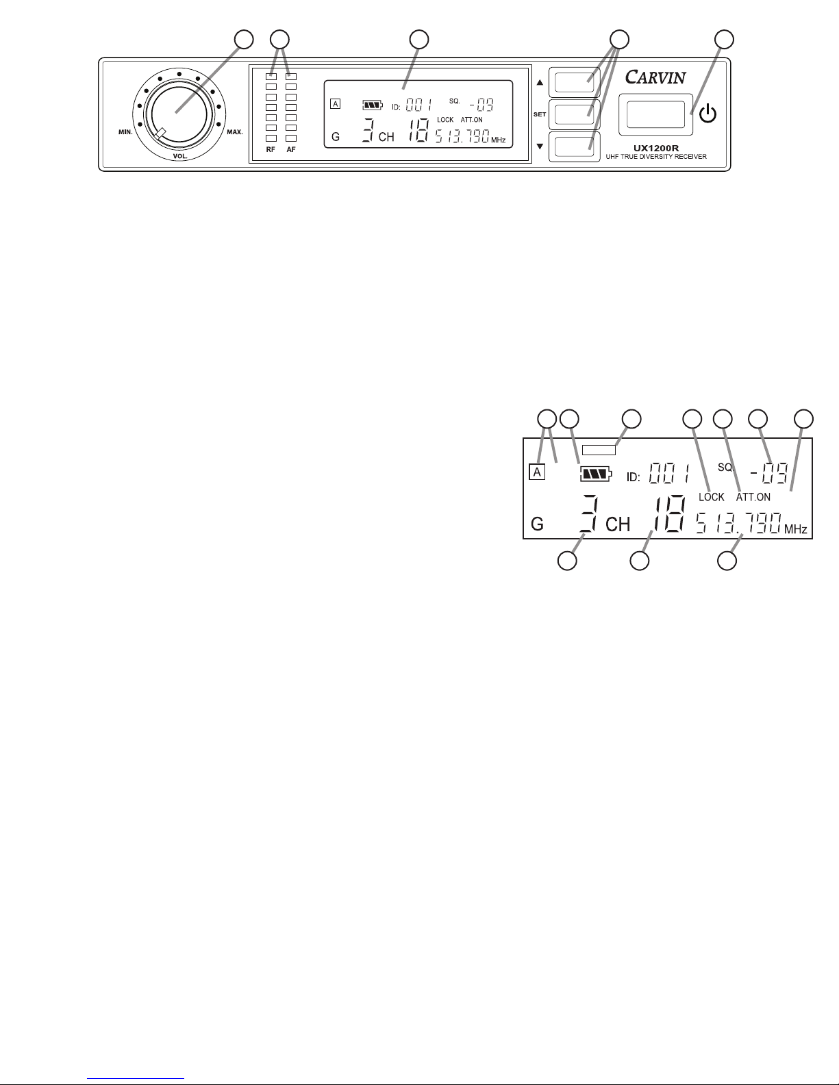
Backlit LCD displays on the receiver and transmitters display channel, group,
battery level and mute status, with 3-button access to frequency, channel and level
settings with LOCK mode to prevent accidental changes. The transmitters also
feature a quick mute feature, quieting the mic or beltpack with a short press of the
power button.
The UX1200/UX600 system has 1441 user selectable frequencies, or you can
select by 6 groups of 23 channels for ease of use with multiple systems. Up to 16
systems can be used simultaneously.
GENERAL SPECIFICATIONS
Group / Channel selections: 6 Groups of 23 channels
Total Frequency settings: 1441 (0.025 Mhz increment)
RF Frequency Band: 506MHz - 542 MHz
RF Bandwidth: 36 MHz
Simultaneous operation: up to 16 units, depending on
RF conditions
UX1200R RECEIVER
Reception format True Diversity, PLL Synthesized
Stability +/- 0.005%
Image Rejection >60 dB
RF Sensitivity <-107dBµ for 12 dB S/N AD
Audio Output Single channel, XLR and 1/4”
Output Impedance 600 ohms
Signal-to-noise >
105 dB
THD <0.6% @ 1kHz
Power Requirement 12VDC, 500mA (AC adapter included)
Dimensions 8.36”W x 1.51”H x 5.66”D
Net Weight 2.4 lbs (with antennas)
2.3 oz (AC adapter)
UX600B BELT PACk TRANSmITTER
Input Connector Mini-XLR
Audio Freq. Response 40-18,000Hz
RF Power Output 10mW or 50mW setting
Stability ± 10kHz
Frequency Deviation ± 48kHz
Spurious Emissions < -50 dBC
Battery AA 1.5V alkaline qty 2
Dimensions 2.45” x 3.875”x 0.94” (w/o clip or ant.)
Net Wt (no battery) 2.5 oz
UX600B ACCESSORIES:
UXGT
1/4” INSTRUMENT CABLE FOR UX600B
UX-LP1
LAVALIER MIC FOR UX600B
UX-Hm3
(black) HEADSET MIC FOR UX600B
UX-Hm3T
(tan) HEADSET MIC FOR UX600B
GETTING STARTED QUICkLY
If you’re like most new owners, you’re probably in a hurry to use your wireless system.
To start, you must have the receiver (Carvin UX1200R), a transmitter (Carvin UX600M
handheld mic, or the Carvin UX600B with a compatible mic UX-HM3 / UX-LP1 or UXGT
cable plugged into an instrument), an XLR or 1/4” cable, and a sound system or instru-
ment amplifier to hear the signal through.
1. TRANSmITTER CONNECTIONS Insert 2 fresh AA alkaline batteries into the
transmitter. For the UX600B beltpack, connect the headset mic, lavalier mic, or cable and
instrument to the belt-pack.
2. RECEIVER CONNECTIONS (UX1200R)
Attach the 2 included antennas to the connectors on the rear of the unit.
Connect the included AC adapter to the UX1200R, then plug it into the proper AC power.
Using an XLR cable or shielded 1/4” cable, connect one of the UX1200R outputs to your
sound system or instrument amplifier.
3. RECEIVER POwER ON Turn down the VOLUME of the UX1200R and the
system it is connected to. On the front right of the UX1200R, press the POWER button.
4. TRANSmITTER POwER ON Press the power button on the end of the
UX600M mic or, on the top of the UX600B belt-pack transmitter. The LCD display should
turn on. (when ON: a quick press will MUTE on/off, HOLD to turn OFF)
5. CHANNEL CHECk Check that both the transmitter and receiver display the
same Group-Channel setting.
To change Group and Channel on UX1200R or UX600M/UX600B:
Hold in the SET button until the display shows SETTING for one second, then the first
digit (Group) will be blinking.
Use the UP/DOWN buttons to match the Group on the transmitter and receiver.
Press SET to have the second digit (Channel) blinking, then use the UP/DOWN buttons
to match the channel. Press SET to save and exit.
If using multiple systems, each transmitter/receiver pair must be set to a different group-
channel setting.
6. SOUND CHECk Use the mic or play the instrument as intended. Set the
VOLUME on the front of the UX1200R to a low level (about 9 o’clock). Gradually raise
the output levels on the sound system or amp to a comfortable volume. If distortion
occurs and the UX1200R front panel “AF” audio level meter is showing Orange or Red
LEDs then lower the transmitter levels: UX600M(dB setting), UX600B (SENSIT and ATT
settings). If distortion is still heard, try lowering the preamp level on your sound system
or amp. You can also lower the UX1200R output by -20dB with the “At ON” output
attenuation setting.
RECEIVING INSPECTION - read before getting started
INSPECT YOUR WIRELESS SYSTEM FOR DAMAGE which may have occurred during shipping.
If damage is found, please notify the shipping company and Carvin Audio immediately.
SAVE THE CARTON & ALL PACKING MATERIALS. In the event you have to re-ship your unit,
always use the original carton and packing material. This will provide the best possible protec-
tion during shipment. Carvin Audio and the shipping company are not liable for any damage
caused by improper packing.
SAVE YOUR INVOICE. It will be required for warranty service if needed in the future.
SHIPMENT SHORTAGE. If you find items missing, they may have been shipped separately.
Please allow several days for the rest of your order to arrive before inquiring.
RECORD THE SERIAL NUMBER on the enclosed warranty card and below on this manual for your
records. Keep your portion of the card and return the portion with your name and comments to us.
FOR YOUR RECORDS, YOU MAY WISH TO RECORD THE FOLLOWING INFORMATION:
SERIAL No._________________________________ INVOICE DATE __________________
REGULATIONS AND SERVICING
This device complies with part 15 of the FCC Rules. Operation is subject to the
condition that this device does not cause harmful interference.
CAUTION! Do not attempt to open the receiver or transmitter. To do so will void
the warranty, and may cause improper operation. The circuits inside the receiver and
transmitter have been precisely adjusted for optimum performance and compliance with
federal regulations. Refer servicing to qualified service personnel. No user-serviceable
parts inside. Do not expose to rain or moisture.
wARRANTY
90 days on all electronic components. Does not cover broken parts caused by
normal wear or abuse.
UX1200R WIRELESS RECEIVER, UX600 TRANSMITTERS
UX1200R
UX600B UXGT UX-LP1
UX-Hm3
UX600m
UX600m HANDHELD mIC TRANSmITTER
Polar Pattern Unidirectional
Audio Freq. Response 50-16,000Hz
RF Power Output 10mW or 50mW setting
Stability ± 10kHz
Frequency Deviation ± 48kHz
Spurious Emissions < -50 dBC
Battery AA 1.5V alkaline qty 2
Current Consumption 30 mA typical
Battery Life Approx. 25 hours
Dimensions 10.3”L x 1.97” dia.
Net Wt (no battery) 12.5 oz
16262 WEST BERNARDO DR. SAN DIEGO, CA 92127
800-854-2235 CARVINAUDIO.COM
USER MANUAL
UX1200/UX600 SYSTEm SPECIFICATIONS

1. VOLUmE (VOL.) Sets the output level for the XLR and 1/4” output jacks. The output level for the XLR is also affected by the “At” (-20dB attenuator) setting.
For use with a typical electric guitar and amp, set VOL. to about “4 o’clock”, on the UX600B set sensitivity (SEnSiT) to “-9dB” and set attenuator (ATT) to “ON”.
2. RF AND AF LEVEL - LED mETERS Indicate the strength of the Radio Frequency (wireless) and Audio Frequency (audio) signal levels.
If the RF meter is low or off, the transmitter’s carrier signal is not being picked up by the receiver. Be sure the transmitter and receiver frequencies match.
If the RF level is still low or fades in and out you may need to change frequency, or set the transmitter’s RF Power to “HI”. Also check antenna connections.
The AF meter registers level of the voice or instrument. If it does not register with a voice at the mic or instrument playing, there is a problem with the audio
signal being received by the transmitter. Check that the UX600B transmitter’s microphone wire or instrument cable is properly connected. On the UX600M
mic try increasing the level (dB) setting, or with the UX600B beltpack increase the level (SEnSiT) setting or set the UX600B attenuator (ATT) function to OFF.
If the AF meter lights the top two orange and red LEDs the audio signal to the transmitter is too high and may be distorted. On the UX600M mic reduce the
level (dB) setting. On the UX600B beltpack lower the level (SEnSiT) setting, in addition you may set the attenuator (ATT) to ON for more headroom.
3. DOwN, UP AND SET BUTTONS Press and hold the SET button to access the different settings, and change settings with the UP/DOWN.
4. POwER BUTTON Press once to turn ON. Hold for 2 seconds to turn OFF.
5. DISPLAY - BACkLIT LCD
A. GROUP and B. CHANNEL Displays the Group and Channel setting if one is selected.
C. FREQUENCY Displays the receiving Frequency, set by the Group-Channel or Frequency setting.
If you select a Group and Channel setting, the related Frequency will be automatically selected.
D. “A” or “B” Reception indicator Due to the nature of True Diversity reception, the logic
circuits continually select between the A or B antennas for the best signal reception.
E. BATTERY LEVEL Displays the battery level of the remote transmitter.
F. GROUP MODE ICON Indicates when the Group-Channel feature is being used to select the frequency. The “FREQ” icon indicates a manual frequency selection.
G. LOCK ON Screen lockout is engaged. No settings can be changed until the lock is turned off.
H. ATTENUATOR ON Shows the -20dB attenuator for the XLR output signal is engaged.
I. SQUELCH SETTING Displays the SQUELCH level setting.
J. MUTE INDICATION Displays when the transmitter MUTE function is used, or when output is automatically muted due to lack of RF signal or Squelch gating.
CHANGING SETTINGS:
Press and hold the SET button until “SETUP” is displayed. An icon for the chosen setting will be flashing on the top row of the screen and the setting to be edited will display.
To select a different setting to edit, press the SET button again. Adjust the setting with the UP/DOWN buttons. Press the SET button again to save and exit.
GROUP, CHANNEL: (example: G3 CH18; group 3, channel 18)
Set the UX1200R receiver first and then set the transmitter to the same settings. This automatically sets the FREQUENCY.
*NOTE: The GROUP-CHANNEL method is recommended especially when using multiple systems (instead of using the manual Frequency setting).
Set each transmitter-receiver pair to a different Channel, but use the same Group setting for all. If too many Channels have outside interference, change all units to a different Group.
The GROUP-CHANNEL assignments are pre-calculated and designed to avoid crosstalk or other types of interference between wireless channels within the same group, even
frequencies which are far apart can cause unwanted effects due to harmonics or additions and subtractions in carrier signal waves.
- If the Group-Channel settings on transmitter and receiver are matched but there is no sound; Check the levels on your sound system or amp and check all connections. On the
UX1200R check the RF and AF signal meters for response, antenna connections and SQUELCH setting. On the UX600M or UX600B check batteries and UX600B input connection.
FREQUENCY: (example: 530.950
MHz
) The first 3 digits change in 1 MHz steps, the second 3 digits change in 0.025 MHz steps.
If you select a GROUP and CHANNEL setting, the FREQUENCY is automatically set and should not be changed. If you need to choose a specific frequency you can change it here.
SCAN: (SC OFF, SC ON) The SCAN feature detects the next available open RF channel. If RF activity is sensed on or close to a channel, that channel will be skipped.
To use the SCAN feature, first check that the UX1200R receiver’s SCAN setting is ON.
Turn OFF the transmitter for THIS receiver, but turn ON any OTHER transmitters you will be using in this area. NOTE: Set all UX600/UX1200 units to the same Group.
Access the Channel setting, and press the UP or DOWN button. The display will read “SCAN__” for a few seconds. When the next open Channel is displayed, press the SET button
to store it. Match the UX600M or UX600B transmitter to this Group and Channel after the UX1200R receiver has been set. If “NoFREE” appears on screen, select a different group.
SQUELCH: (example: -9) range of -5 to +10. The SQUELCH setting is used to reduce interference by rejecting background RF signals that fall below the SQUELCH level. Increasing
the SQUELCH setting will increase the level of RF signal required to pass an audio signal through the receiver.
Setting the SQUELCH too high may cause intermittent sound from your transmitter. In this case lower the SQUELCH, or if you are still experiencing interference you can set the
UX600M or UX600B transmitter’s RF POWER setting to “rF Hi”.
ATTENUATION: (At OFF, At ON): Decreases the output level at the XLR output by -20dB. If your mixer preamp is being overdriven with VOL. turned low, use the “At ON” setting.
SCREEN LOCK: (LO OFF, LO ON): Set to “LO ON” to prevent accidental changes or tampering. If set to “LO ON”, only the Lock screen setting will be accessable.
UX1200R RECEIVER
35 421
MUTE
GROUP
E
DI
BA C
GHJ
F

UX600B BELT-PACk TRANSmITTER
1. BATTERy INSTALLATIoN
To access the battery compartment, slide the rear cover panel off
toward the bottom. Insert fresh AA alkaline batteries, observing
correct polarity as marked inside the battery compartment. Slide
the cover back on until it locks.
2. PoWER / MUTE BUTToN
To turn the beltpack ON, press and release the white button on
the top of the unit.
The power button LED and front display backlight will turn on.
The channel/frequency digits and battery status symbol will be
displayed.
To MUTE the output, quickly press and release the button.
“RF OFF” will appear on the display for 1 second.
The backlight will blink while muted, and the “no speaker”
symbol will show on the display.
To UNMUTE, quickly press and release the button again.
“RF ON” will be displayed for 1 second.
To turn the unit OFF, press and hold the button for about two seconds, the screen will
display “OFF” for 1 second, then the UX600B will turn off.
3. SETTINGS BUTToNS
Press and hold the SET button until “SETUP” is displayed.
The first digit will be blinking to show the setting can be changed.
Select the setting to be changed with short presses of the SET button.
Adjust the setting with the UP/DOWN buttons.
Press the SET button again to save and exit.
GROUP and CHANNEL: (example: 1- 8; group 1, channel 8)
Set to both numbers match the UX1200R receiver.
FREQUENCY: (example: 530.950) and the “
MHZ”
symbol appears in the lower right.
Allows manual selection of the frequency, however the GROUP-CHANNEL setting is rec-
ommended. (see UX1200R - FREQUENCY)
The first 3 digits change in 1 MHz steps, the second 3 digits change in 0.025 MHz steps.
SENSITIVITY: “SEnSiT” will display for 1 second, then the setting value.
(example: 0 dB) Settings from +12dB to -18dB, in 3 dB steps.
Sets the level of the internal preamp to the transmitter. You may want to increase this set-
ting for soft speaking when used with microphones, or set it lower to prevent overloading
from powerful vocals, or when connected to an instrument. The recommended setting for
electric guitar is “-9dB”, with the attenuator (ATT) set to ON (see next paragraph).
ATTENUATOR: (Att OFF, Att ON) Adds an attenuation circuit when used.
Recommended when connecting instruments with the UXGT cable, or with strong vocals
through the UX-HM3 or UX-LP1 mics. If the SENSITIVITY setting has been turned all the
way down and the transmitter is still being overdriven, setting ATT ON will add a buffer to
the internal preamp to allow more headroom.
RF POWER: (rFP Hi, rFP Lo) Changes the transmitter’s RF power output.
Use the “rFP Hi” setting if you experience dropouts which cannot be remedied by chang-
ing the channel/frequency, or if the transmitter will be used far from the receiver.
Set this to “rFP Lo” if the sytem is causing interference with another system, if used very
close to the receiver, or if you are hearing unexplainable distortion at high audio levels.
SCREEN LOCK: (Loc OFF, Loc ON):
Set to “Loc ON” to prevent accidental changes or tampering. If set to Loc ON, only the
Lock screen will display when settings are accessed. Change the setting to Loc OFF to
allow adjustments.
4. INPUT CoNNECTIoN:
Connect one of the following to the mini XLR
input jack on the UX600B transmitter:
UX-HM3 HEAdSET MIC:
Connect the mic cable to the mini XLR input jack. Place
the mic on the vocalist’s head. Keep the mic a minimum of 2 inches from the mouth to
minimize air hitting the mic.
UX-LP1 LAVALIERE MIC:
Connect the lavaliere mic cable to the mini XLR input jack.
Clip the mic to clothing near the top center of the chest. For optimum sound, position the
mic as close to the mouth with the top of the mic facing up. Test out various positions
along the center of the chest to determine the ideal mic placement. This may vary from
person to person as each voice projects uniquely.
UXGT INSTRUMENT CABLE:
Connect the cable to the mini XLR input jack. Plug
the 1/4” connector into a guitar, bass or other instrument. Turn the volume down on the
receiving mixer or amplifier before turning the transmitter power ON.
Push the
round
button to
release
the cable
1. BATTERy INSTALLATIoN
(1.A, 1.B, 1.C)
While holding the lower part of the transmitter body, unscrew the windscreen capsule
(1.A) on top of the mic. Press the release clip (1.B) to eject the battery dock (1.C) and
remove it from the body. Install fresh AA alkaline batteries, observing correct polarity as
marked inside the battery compartment. Replace the battery dock and make sure the clip
snaps into the locked position so the battery dock will not slide out. Match the rectangular
stub on the windscreen capsule to the 4 pins in the mic body and turn clockwise until tight.
2. PoWER / MUTE BUTToN
To turn the mic ON, press and release the button on the bottom end of the mic.
The display and backlight will turn on.
The channel/frequency digits and battery status symbol will be displayed.
To MUTE the mic, quickly press and release the button.
“RF OFF” will appear on the display for 1 second. The
backlight will flash while muted.
To UNMUTE, quickly press and release the button again.
“RF ON” will be displayed for 1 second.
To turn the mic OFF, press and hold the button for about
two seconds, the screen wil display “OFF”, then turn off.
3. SETTINGS BUTToNS
To access the settings buttons, slide the black plastic cover off the end of the mic.
CHANGING SETTINGS:
Press and hold the SET button until “SETUP” is displayed. The setting to be edited will
be blinking. Press the SET button again to select a different setting to edit.
Adjust the setting with the UP/DOWN buttons.
Press the SET button again to save and exit.
GROUP and CHANNEL: (example: 1- 8; group 1, channel 8)
Set to both numbers match the UX1200R receiver.
FREQUENCY: (example: 530.950) and the “
MHZ”
symbol appears in the lower right.
Allows manual selection of frequency, however the GROUP-CHANNEL setting is recom-
mended. (see UX1200R - FREQUENCY)
The first 3 digits change in 1 MHz steps, the second 3 digits change in 0.025 MHz steps.
LEVEL: (example: 0 dB) range of +12dB to -18dB, in 3 dB steps.
Sets the level of the internal mic pre to the transmitter. You may want to increase this set-
ting for soft speaking, or set it lower to prevent overloading the mic from powerful vocals.
RF POWER: (rF Hi, rF Lo) Changes the transmitter’s RF power output.
Use the “rF Hi” setting if you experience dropouts which cannot be remedied by changing
the channel/frequency, or if the transmitter will be used far from the receiver.
Set this to “rF Lo” if the sytem is causing interference with another system, if used very
close to the receiver, or if you are hearing unexplainable distortion at high audio levels.
SCREEN LOCK: (Loc OFF, Loc ON): Set to “Loc ON” to prevent accidental changes or
tampering. If set to Loc ON, only the Lock screen setting will be accessable.
1
1.A
3
1.C 3
1.B
UX600m HANDHELD mICROPHONE
UX-HM3
(black)
or
UX-HM3T
(tan)
UX-LP1
UXGT
4
2

UX1200revB 18AUG16
LIMITED WARRANTY
90 days on all wireless electronic components. Does not cover cables, connectors, or broken parts caused by normal wear and tear or by dropping. Shipping costs are the respon-
sibility of the customer. CARVIN CORP. DOES NOT PAY FOR PARTS OR SERVICING OTHER THAN OUR OWN. A COPY OF THE ORIGINAL INVOICE IS REQUIRED TO VERIFY YOUR
WARRANTY. Carvin Corp. assumes no responsibility for horn drivers or speakers damaged by this unit. This warranty does not cover, and no liability is assumed, for damage due
to: natural disasters, accidents, abuse, loss of parts, lack of reasonable care, incorrect use, or failure to follow instructions. This warranty is in lieu of all other warranties, expressed
or implied. No representative or person is authorized to represent or assume for Carvin Corp. any liability in connection with the sale or servicing of Carvin Audio products. CARVIN
CORP. SHALL NOT BE LIABLE FOR INCIDENTAL OR CONSEQUENTIAL DAMAGES.
RETURNING AN ITEM
Before you return an item, please visit www.carvinaudio.com and review the TROUBLE SHOOTING guide to verify that you have a defective unit. Thoroughly check your connections
and all settings. Sometimes it’s as simple as a mismatched frequency or an improper connection.
If you wish to return an item, visit www.carvinaudio.com and follow the RETURN PROCEDURE and shipping instructions. Start by completing the RMA RETURN FORM. Describe
each problem in writng and include a copy of your original invoice if under warranty.
If you do not have a copy of your original invoice, contact our accounting department at (800) 854-2235 to obtain a copy.
If your unit is out of warranty, you will be charged the current FLAT RATE for parts and labor to bring your unit up to factory specifications.
1. Use fresh alkaline batteries, or fully charged rechargeables. Transmitter battery level is displayed on both reciever and transmitter.
2. If using more than one system, use the GROUP-CHANNEL assignments instead of the Frequency setting to avoid cross-talk or other interference.
All transmitter/receiver pairs should be on the same GROUP, but different CHANNELs.
3. Position the receiver so that it has the fewest possible obstruction between it and the normal location of the transmitter. Line-of-sight is best.
4. The transmitter and receiver should be as close together as conveniently possible.
5. The receiver antennas should be in the open and away from any metal structures or cement walls.
6. Turn off the transmitter when not in use. Remove the batteries if the transmitter is not used for a period of time.
TIPS TO OBTAIN THE BEST wIRELESS RESULTS
IMPORTANT RF OPERATION NOTES
Please note that wireless audio frequencies are shared with other wireless services:
According to Federal Communications Commission regulations, “Wireless microphone operations are unprotected from interference from other licensed operations within the
band. If any interference is received by any Government operation, the wireless microphone must cease operation…”
If you encounter receiving interference (from other than an operating TV station), often it can be eliminated by changing to a different channel or frequency.
This manual suits for next models
1
Table of contents