CAS EXI-200AD User manual

`
2
이미지 추가

3
Contents
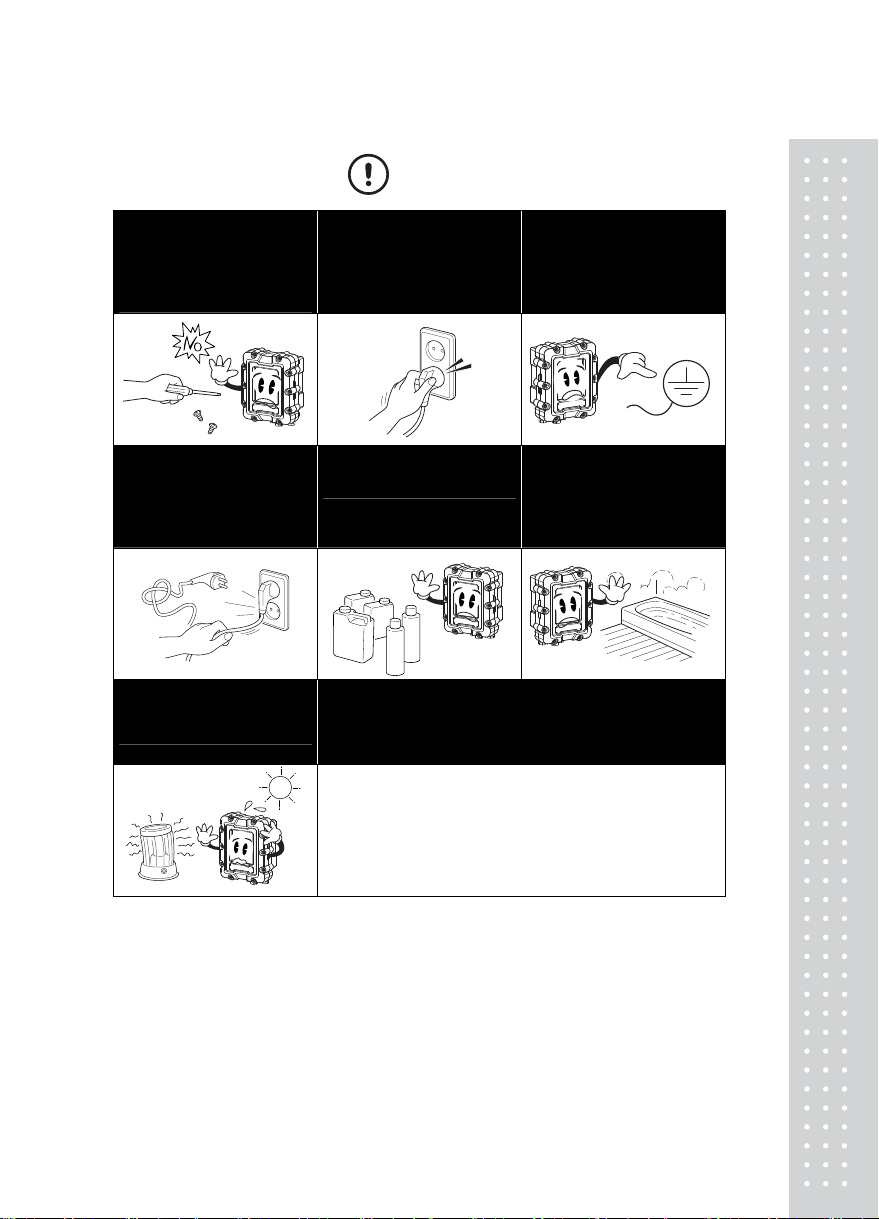
Cautions for Safety...................................................................................6
1. Normal Requirements .........................................................................9
1.1 Application Range...............................................................................................................9
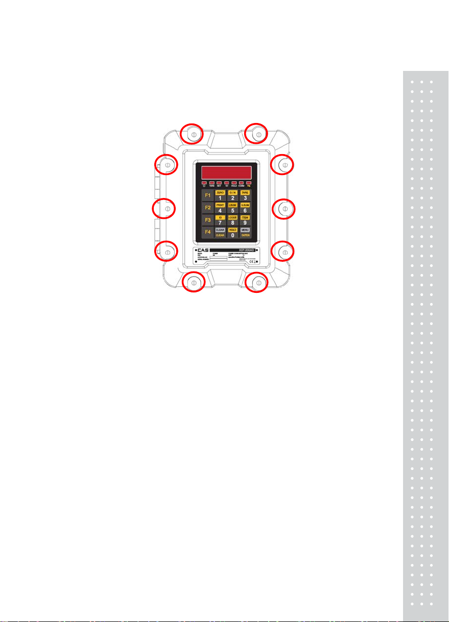
1.2 Transport, assembly and installation.................................................................................9
1.3 Function, Operation and Use.......................................................................................... 13
1.4 Maintenance and Cautions ............................................................................................. 15
2. Technical Specifications...................................................................16
2.1 Product Specifications ..................................................................................................... 16
2.2 Product Labelling ............................................................................................................. 16
2.3 Product Structure and Composition ............................................................................... 17
2.4 Handling Cautions ........................................................................................................... 17
3. Features ...............................................................................................18
3.1 Features............................................................................................................................ 18
3.2 Main Functions................................................................................................................. 18
3.3 Product Specifications ................................................................................................... 19
4. External Explanation..........................................................................21
4.1 External Specifications .................................................................................................... 21
4.2 Frontal Surface Explanation............................................................................................ 22
4.3 Display Explanantion ....................................................................................................... 24
4.4 Key manual ...................................................................................................................... 25
5. Internal Explanation...........................................................................27
5.1 Internal Explanation......................................................................................................... 27
5.1.1 Power Connector (AC, DC) ..................................................................................... 28
5.1.2 Load Cell Connector................................................................................................. 30
5.1.3 RS-232, RS-422/485 Connector ............................................................................. 32
5.1.4 Relay Input(Option)................................................................................................... 34

`
4
6. Weight Calibration Mode...................................................................35
6.1 What is weight calibration? ..............................................................................................35
6.2 How to enter the weight calibration mode......................................................................35
6.3 Weight calibration menu (CAL1 – CAL9).......................................................................36
7. Weighing Mode...................................................................................45
7.1 Zero-set Function .............................................................................................................45
7.2 Tare function......................................................................................................................46
7.3 Item number changing .....................................................................................................46
7.4 Set Point changing ...........................................................................................................47
7.5 Subtotal Print.....................................................................................................................47
7.6 Total Print...........................................................................................................................48
8. Test Mode.............................................................................................49
8.1 Key Test.............................................................................................................................50
8.2 Display Test.......................................................................................................................50
8.3 AD Test ..............................................................................................................................51
8.4 Communication Test.........................................................................................................51
8.5 External Input/output Test_OPTION ...............................................................................51
8.6 A-OUT Test _OPTION .....................................................................................................52
8.7 1/10 division Test ..............................................................................................................52
8.8 EEPROM Test ..................................................................................................................52
8.9 RTC Test_OPTION ..........................................................................................................52
9. Set Mode ..............................................................................................53
9.1 How to enter set mode.....................................................................................................53
9.2 General Function ..............................................................................................................56
9.3 Communication Setting....................................................................................................62
9.4 Analogue Output Setting..................................................................................................67

5
9.5 Hardware Set Function ................................................................................................... 69
9.6 Relay Setting .................................................................................................................... 70
9.7 TCP IP .............................................................................................................................. 76
9.8 Print Function Setting ...................................................................................................... 79
10. Error Message...................................................................................84
10.1 Errors that can occur in weight calibration mode ........................................................ 84
10.2 Errors that can occur in weighing mode ...................................................................... 85
Appendix 1> Data format ......................................................................86
Appendix 2> Command Mode 1 Description....................................88
Appendix 3> Command Mode 2 Description....................................89
Appendix 4> Command mode 3 Description....................................90
Appendix 5> ASCII Table.......................................................................90
Appendix 6> MODBUS-RTU PROTOCOL..........................................91

`
6
Cautions for Your Safety
‘Please comply with 'Cautions for Your Safety', which will lead you to use the product safely and
properly to prevent any dangerous situations.
■Cautions are divided into 'Warning' and 'Alert', which mean as follows.
■Keep this manual in a place where product users can find out, after finish reading it.
'Warning' means a great possibility led to the death or heavy injury when instructions are violated.
'Alert' means a great possibility led to the injury or material damage when instructions are violated.

7
Warning
Never disassemble, repair or retrofit the
product.
It might exclude the product
from the quality assurance and cause
the damage to devices, electric shock or
fire.
Ensure the power plug to be fully
inserted to prevent shaking.
Any instable connection might cause
electric sparks to set fire.
Ensure the grounding of the product.
Poor grounding might cause failure or
electric shock upon electric leak.
.
Do not damage, process,
excessively jerk, bend or twist the
power cord.
It might damage the power cord to
cause fire or electric shock.
Keep any combustible spray or fire
source away.
It might cause fire.
Do not spray water to the outside of the
product or use it in any humid place.
It might deteriorate the insulation of
electric parts that can cause the electric
shock, fire risk or weighing errors.
Do not place the product to the direct
sunlight or near any hot object like a
heater.
It might cause fire.

`
8
Attention
Check the weighing error anytime for
the accurate weighing.
Any use out of the allowed tolerance
for the careless use or other causes
might not ensure the accurate
weighing.
Avoid any sudden shock to the product.
It might damage the product to fail the
accurate weighing.
Find a proper place to attach the rubber
pad at the bottom of the indicator,
which was shipped together.
Do not use the product at a place with
sudden temperature changes or severe
vibrations.
It might cause the weighing error or
failure.
Do not install the produce at a place with the excessive electromagnetic wave.
It might cause the wrong weighing.

9
1. Normal Requirements
1.1 Application Range
This product is an explosion-proof and dust ignition-proof product for locations of gas, steam or
chemical use and other hazardous areas.
■Explosion-proof Structure and Class
Explosion proof Dust ignition proof
Explosion-
Proof Class Ex d IIB +H2 T6 IP66 Ex tD A21 85℃IP66
Gas group IIB and H2 (hydrogen region)
Temp Class T6 (85℃)
1.2 Transport, assembly and installation
1.2.1. Transport
(1) Packaging method and specification
(a) After removing any external/internal foreign matter on the product, clean, dry and apply
corrosion preventive treatment on exposed sections.
(b) Measures are needed to prevent foreign matter from entering openings within the product.
(c) The packaging must correspond with the size and weight of the contents, and internal
fillings that can act as a buffer must be used such as air caps or newspapers.
(d) The product must be appropriately protected to prevent rust and corrosion.
(2) Transport Method
If stacked high during transportation, there is possibbility of damage by fall due to the weight of
the product. Therefore suitable protective equipment or devices must be used when transporting.

`
10
1.2.2.Assembly and Installation
(1) Assembly
This product is fully assembled when shipped and there is no need of separate assembly by
the user.
(2) Installation
When installing electrical instruments in an explosion-proof area, compare the below
requirements with the technical specifications beforehand to confirm correspondence.
(a) Normal Requirements.
①Use installation method (floor installation, wall installation etc.) and installation form
(slope allowance etc.) that is appropriate with the explosion prevention electric
instrument's usage conditions.
②Bolts, nuts, metallic etc. used in the installation must have sufficient mechanical
strength. Also, use materials and surface treatment that is clearly based on installation
location.
③Ensure recharge sections are not exposed.
(b) Installation Location
①Install where it is convenient to operate, manipulate, adjust, maintain etc.
②If possible avoid locations exposed to moisture or humidity and avoid high humidity
areas.
③If possible avoid areas of corrosive liquid dispersion and near release of corrosive gas.
④Avoid locations close to high temperature heating elements such as heat pipes, steam
pipe etc. and areas of rapid temperature fluctuation.
⑤Avoid locations that is heavily affected by vibrations from mechanical devices etc.
⑥Do not install in locations of high pressure or heavy electric noise.
⑦Do not install in location of strong direct sunlight.
(c) Installation method must be suitable to the purpose.
(d) Power connection and wiring.
①Use a cable with internal ground wire for the power line and install separately from
the signal line.
②Connect the power cord with the power socket in an explosion proof area and when
connecting in an explosive area always connect using "plugs and receptacles'.
③Connect the power and signal lines through a designated location. (Refer to 4.2.2)

11
(e) Wiring Method during Installation (power and load cell)
①Refer to "4. External Explanation" and "5. Internal Explanation" of this manual.
②Use an Allen wrench to loosen the front bolts and open the front cover
③Connect an appropriate cable gland (joint screw diameter(M20*1.5)) to the power line. (Refer to 4.2
Front Surface Explanation)
④Connect the power line to the power terminal as depicted in the figure below. Refer to this
manual's "5.1.1 Power Connector" for the wiring order. (Connect the power line using a 4Φ
terminal etc.)

`
12
< AC Type> < DC Type>
⑤Connect an appropriate cable gland (joint screw diameter (M20*1.5)) to the load cell line.
(Refer to 4.2 Front Surface Explanation)
⑥Refer to this manual's "5.1.2 Load Cell Connector" and the wiring blueprint of the load cell
for the wiring order. (Connect the load cell line using pin terminals etc.)

13
1.3 Function, Operation and Use
1.3.1. Inspection and Adjustment
(1) For the explosion-proof instrument, check for following suitability list
(a) Terminal voltage, pole number
(b) The type and specification of replacement parts from each part
(c) Whether the overall control system (control, manipulation, display, notification etc) is
working
(d) Operation and display of auxiliary instruments
(e) Presence of vibration and its intensity.
(f) Inspection of the wiring inlet.
①Whether metallic wiring material suitable to the conduit tube screw section
specifications are used.
②Whether sealing has been installed on conduit cable sections requiring explosion-
proofing.
③The compound must be filled at a sufficient depth and the attachment and hardening
state must be acceptable.
④The state of the attachment of the electronic instrument must be acceptable.
(g) Inspection of connection area between wiring and electric instrument etc.
①Proper access of terminal sign, polar circuits.
②The connection area must be sufficiently tight and measurement must be made to
prevent loosening.
③Connection section without terminal blocks etc must be clearly insulated.
(h) Inspection of container cover
①There must be no damage or foreign matter on the cover access section or screw threads
and it must be coated with non-hardening oils.
②When packing is used for dust and water proofing, it must be installed properly.
③The screws must not be faulty and sufficiently tightened.
(i) The state if operation based on explosion-proof structure and conditions of use must be
acceptable

`
1
4
< Basic Inspection Items >
Item Method Inspection Content Notes
Container
(explosion-proof
box)
By eye There must be no external damage (rust, dust)
cleaning,
corrosion
protection
Display window By eye There must be no damage by scraping etc cleaning
Screws By eye,
touch There must be no loosening, dust or rust tighten, cleaning
Button By eye,
touch There must be no loosening or breakage tighten, replace
Power line inlet
Cable gland
By eye,
touch
There must be no damage, resolution or
loosening tighten, replace
Electric
instrument (PC) By eye There must be no external damage and
damage to power status cleaning
1.3.2. Operation
(1) Operation Method
(a) Check the cable connection and metallic wiring state of the installed product.
(b) Apply power to the installed product.
(c) Check if it is functioning normally.
(2) Operation Cautions and Prohibitions
(a) Before using the product the learn user manual and use and install according to the
given method.
(b) This product must be constructed by qualified expert electrical construction personnel.

15
1.4 Maintenance and Cautions
1.4.1. Maintenance
(1) This product requires continued management through periodic inspection (1 time or more
per month recommended).
(2) When maintaining electrical instruments the following items must be checked.
(a) There must be no damage to the container connection surface (screw).
(b) There must be no damage or cracks from shock to the container exterior.
(c) The screws must be uniform and sufficiently tight.
(d) Corrosion prevention treatment must have been sufficiently carried out to prevent rust on
the container connection surface or exterior.
1.4.2. Preparations
(1) Prepare tools, materials, replacement etc.
(2) Determine and check the need for insulation and insulation range.
(3) Check the presence of explosive gas and handle as a non explosion-proof area.
(4) Operator knowledge and capacity.
(5) Documents and diagrams related to the explosion prevention area (division diagram etc.).
1.4.3. Cautions
(1) When inspecting during application of current, the body (cover) of the explosion-proof
electrical instrument must not be opened.
(2) When maintaining in an explosion-proof area, ensure no shock sparks occur from tools
etc.
(3) When maintaining and repairing, disassembly and assembly work related to the electrical
instrument's explosion-proof capacity is accompanied. Therefore the explosion-proof
capacity must be checked for all parts.
※If the user cannot maintain or determine cause of failure, please contact the manufacturer.
(Contact numbers are included in the back of the manual)

`
16
2. Technical Specifications
2.1 Product Specifications
Product Name Indicator
Mode Name EXI-200AD
Explosion proof Ex d IIB +H2 T6 IP66
Explosion proof
structure Dust ignition proof Ex tD A21 85℃IP66
Material container Aluminum (AL)
100 V ~ 240 V , 50/60 Hz
110 V 0.15 A
AC Type
220 V 0.08 A
Power
DC Type 12~24 V 1.5 A
Product Size 218 (W) x 257 (H) x 152 (D)
Temperature Range -20 ℃~ +40 ℃
Product Weight Approx.15 kg
Fuse Capacity 2 A 250 V
Power Consumption Approx. 3.9 W
2.2 Product Labelling

17
2.3 Product Structure and Composition
2.3.1. To form the body, an aluminum composite material suitable for the shaping and usage
requirement of the product was selected.
2.3.2. The protective galss is tempered, explosion-proof structure formed by heat treatment and
metallic molding to be capable of maintaining sufficient strength.
2.3.3. The wiring connections must be made of metal conduit tubing or a product of equal
capacity.
(For all wiring material, only those that have been certified as explosion proof, or a greater
safety level or passed the explosion proof efficiency inspection and are still within the
certification expirary date are used)
2.3.4. When the product needs to be maintained or repaired after power is supplied to it,
“ Opening is not permitted during when electic currents are applied and before
opening the cover the power must be shut off.”
2.4 Handling Cautions
2.4.1 Handling Cautions
(1) If the instrument is dropped or shock is applied to it there is a possibility of a reduction in
capability. Therefore handle with care.
(2) If the instrument needs to be opened for installation, inspection, maintenance etc., the
power must be cut and caution must be taken not to supply power when it is still open.
(3) When opening or closing the instrument be careful not to cause faults on the connecting
surface. When locing the bolts make sure there is no foreign matter on the connecting
surface and use tools to completely tighten.
(4) Do not open when applying electric currents

`
18
3. Features
3.1 Features
■High speed, High accuracy
■High speed micro processor adoption
■A/D conversion speed : Maximum 200 times/sed
■Appropriate for weight and measurement system
■Easy operation and various options.
■Simple and prompt Full Digital Calibration
(SPACTM: Single pass automatic span Calibration)
■RFI./EMI screened
■Watch Dog circuitry (System restoration)
■Weight Back-up
(Weight memory at sudden power failure)
3.2 Main Functions
■Store date, time and calculated data at sudden power failure.
■Various specification on weight conversion speed.
(Digital filter function)
■Various printer connection. (RS-232C Serial printer)
■Tare weight setting with keys.
■Storage of measured times.
■Set Point input & highest, lowest limit input.
■External input 2 relay.(option)
■External output 4 relay.(option)
■Users can set the desirous max. weight and a division freely.
■Control various external equipment by inner external input/output. (option)
■Print date and time by inner clock.
■Self hardware Test.

19
3.3 Product Specifications
Powersupply Unit
Power supply voltage 10 ~ 24(DC), 100V~240V(AC) V
Max consumption 70 with 350 ΩmA
Temperaturerange
Storage temperature -25 ~ 85 ℃
Operating temperature -20 ~ 40 ℃
Loadcell
Impedance(complete bridge) > 80 Ω
Connection 4 or 6 wires
Loadcell power supply 5 ± 5 % Vdc
Communication
RS485 Half duplex
Baud rate 9600 ~ 115200 BPS
Logicalinputs
Numbers 2
type Optocoupler
Low level voltage 0 ~ 3 Vdc
Higi level voltage 9 ~ 24 Vdc
Current at high level 10 mA @ 24 V mA
Insulation voltage 2500 Vrms
Logicalforusemetrologicalcharacteristics
Class III or IIII
Minimum voltage division per
verification scale division
0.5 uV
Maximum voltage for weighing
range
39 mV
Programmable functions
Acquisition of zero, tare, zero tracking
Physical or theoretical calibration
Slope correction
Non-linearity polynomial correction

`
20
Low pass, band-stop and self-adaptive digital filters
Set points managements
Checkweigher functioning mode
Peak detection functioning mode
Option
Display 7 Segment LED, 4 key
A-Out V-out, I-out
-10 V~10 V
0~24 mA
Relay I/O 2input, 4output
Alibi memory
50,000ea Save
Real time clock
Ethernet 10/100 M

21
4. External Explanation
4.1 External Specifications
Table of contents
Other CAS Measuring Instrument manuals
Popular Measuring Instrument manuals by other brands

ParTech
ParTech OxyGuard Handy Polaris instruction manual

Powerfix Profi
Powerfix Profi HG00384C Operation and safety notes

Cloudray
Cloudray 3DM580S user manual

Stabila
Stabila LD 400 operating instructions

Greyline Instruments
Greyline Instruments SFM 6.1 Installation & operation instructions

Hanna Instruments
Hanna Instruments Gro Line HI981030 instruction manual