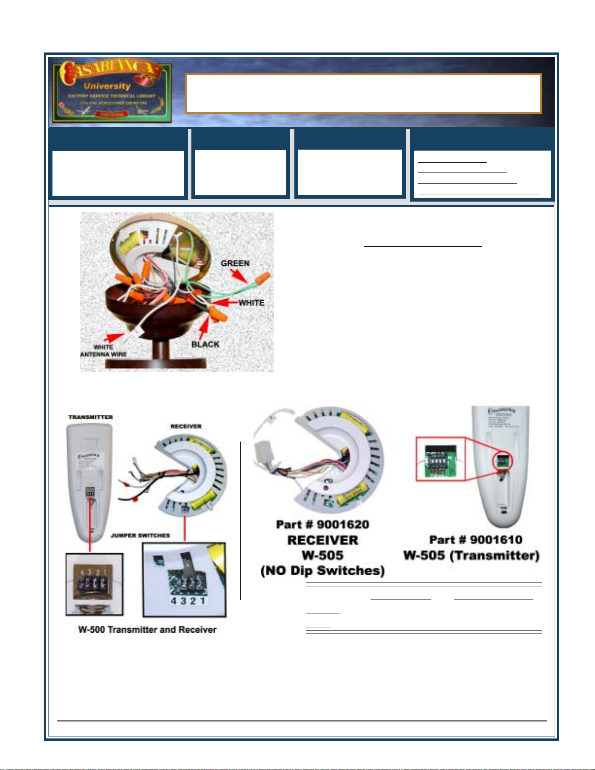
Casablanca Fan Co. - Factory Service Department - Technical Library
10
File Name (TBW500ConvertW505.pmd) RAS 05-18-2007
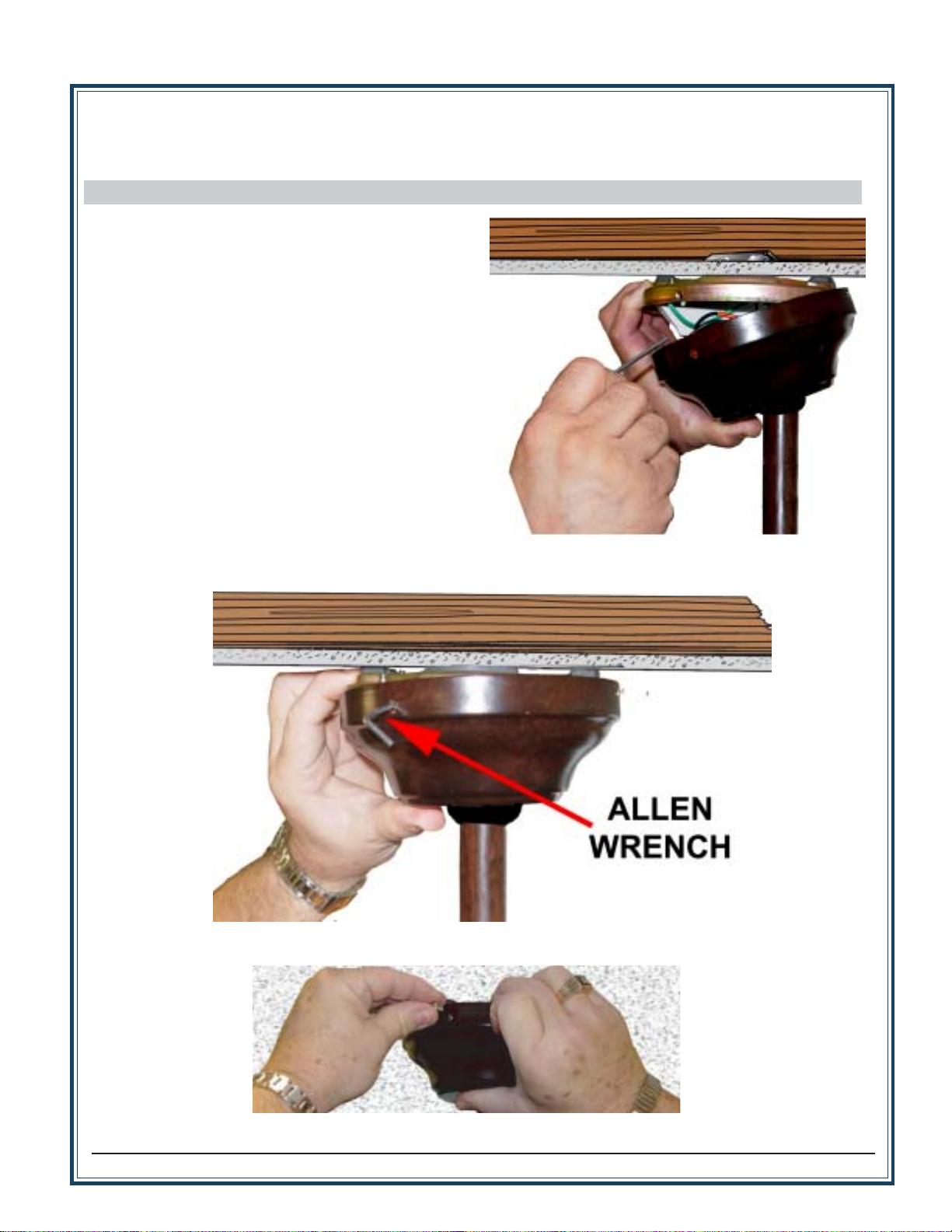
Wall Installation
Step A. Locate a 2x4
wall stud in a conve-
nientlocation.
Step B. Orient the con-
trol bracket as shown
overthe2x4 stud.
Step C. Use the 1”
wood screws in either
theinneroroutermount-
ing holes. Install and
tightenscrews byhand
only.
Note:The wallanchors and
6-32 x 1” screws may be
used in situations where
mountingtoastudisnotpos-
sible. Use the inner mount-
ingholes.Aftersecuringthe
anchor,discardtheanchor’s
pointedscrewsand use the
6-32decorovalheadscrews
supplied.
Changes or modifications not expressly ap-
proved in writing by Casablanca Fan Co. may
void the user’s authority to operate this equip-
ment.
DECOROVALHEADSCREWS
W-505™ CONTROL BRACKET INSTALLATION
This device complies with RSS-210 of Industry Canada. Operation is sub-
jectto the following twoconditions:(1) this device maynotcause interference,
and (2) this device must accept any interference, including interference that
may cause undesired operation of the device.
W-505™ BATTERY INSTALLATION
Install Battery
Press battery into control aligned as
shown.Observeproperpolarity. Replacethe
batterydoor.
Remove Battery Door
Turn control on its front. Twist a coin or use
your finger to unsnap the door A. Lift door
awayfromcontrol B andremove C.
Changes or modifications not
expresslyapprovedinwritingby
CasablancaFanCo.may voidthe
user’s authority to operate this
equipment.
This device complies with RSS-210 of Industry Canada. Operation is subject to
the following two conditions: (1) this device may not cause interference, and (2)
thisdevice must accept any interference, including interferencethatmaycause
undesired operation of the device.
DRYWALLANCHOR
12VBATTERY
WallControls-CONTINUED
WallControls-CONTINUED
W-505™