INTELLIGENT CHARGING
TS25 MKII Battery Charger Analyser Operator Manual
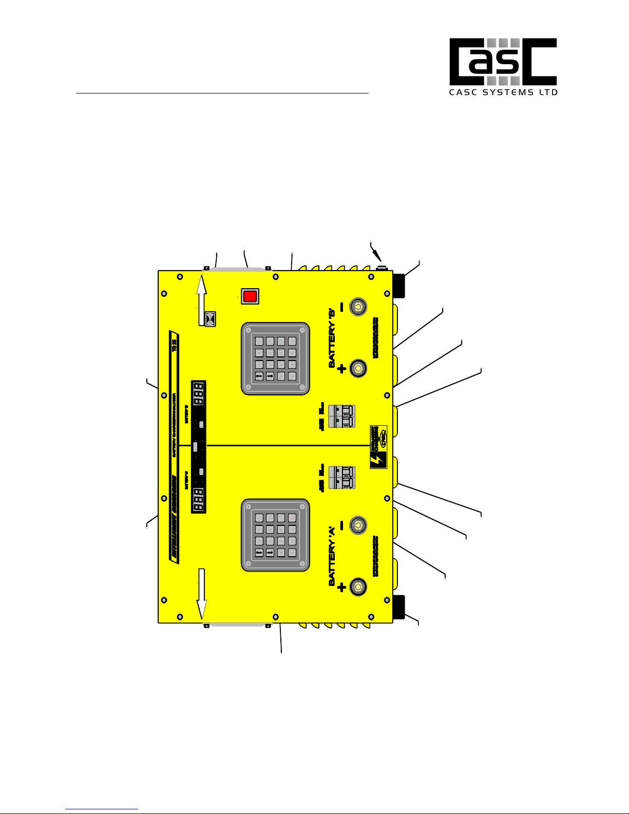
2 TS25 MKII DESCRIPTION
The TS25 MKII Dual Channel Battery Charger / Analyser is an electronically
controlled combined universal battery charging unit with built in battery analysing
capabilities It is housed in a heavy-duty metal enclosure designed to free stand on
a workbench As it is supplied it is configured for use from a standard 240V 50/60Hz
supply
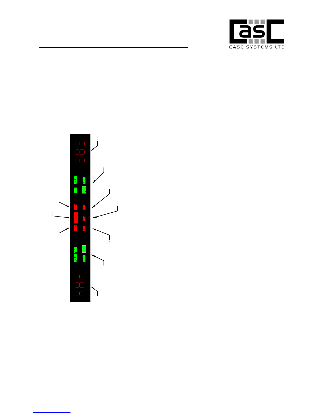
Equipment control is via an interactive numeric display and led state indicators Data
entry is via two 16-key keypads Each channel displayed data and data entry is
independent of the status of the other channel So new processes can be set up
even when the other channel is in the middle of a charge or capacity test
Battery data is stored internally in the unit in battery-backed memory A list of
commonly used batteries is included along with the accepted charging and testing
data The operator can extend or modify this list by entering the details of the
battery to be included on the display and keyboard The battery library data can be
restored to the defaults by a special key sequence permitted via the keyboard
Batteries are connected to the front of the unit by means of two individual heavy
duty connectors Connection to the battery has to be made via the appropriate
connectors for that battery Contact Intelligent-Charging for special lead sets made
to order
The TS25 MKII has extended operating capabilities compared to its predecessor the
TS25 Maximum charge current has been increased to 12A per channel, and
capacity testing still remains at 25A per channel
The TS25 MKII still has paralleling mode where using a common paired cable both
channels can be run in parallel to provide a charge capability of 24A and a capacity
test capability of 50A
There are two capacity test programs built into the unit and these can be selected
via the configuration menu and capacity testing can be performed such that it will
stop testing when a battery reached 100% or less, or alternately can carry on
capacity testing until the battery reached the set termination threshold and thus
reporting the actual battery efficiency greater than 100%
There are three charging modes built into the unit, for Lead Acid (Pb) constant
voltage charging can be performed for a fixed period of time and for Nickel Cadmium
(NiCd) constant current charging can be performed with termination on time and
over voltage parameters, and also for Nickel Cadmium batteries a new charge mode
which allows a constant current charge to be performed up until a voltage set point,
Doc: DWG1044-09-R14 TS25 MKII Operators manual.odt Page 5 of 46 Copyright Material of CasC Systems Ltd © 2015
Printed On : 02/02/15