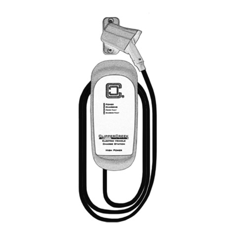
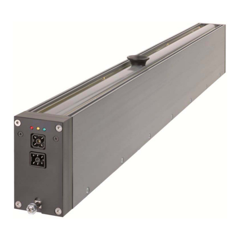
ClipperCreek LCS Series User manual

ClipperCreek, Inc.
Innovative Infrastructure for
Electric and Hybrid Vehicles
• • • • • • •
Model LCS
User’s Manual
With Isolation Monitor for 230VAC

LCS 230VAC Isolation Monitor User’s Manual
PLEASE NOTE
This user’s manual includes the latest information at the time of printing.
ClipperCreek, Inc. reserves the right to make changes to this product without further
notice. Changes or modifications to this product by other than an authorized service
facility may void the product warranty.
If you have questions about the use of this product, contact your customer service
representative. Refer to the Customer Support section located in this guide.
LCS for 230VAC Isolation Monitor User’s Manual, Version 08, April 2016
LCS for 230VAC Isolation Monitor User Manual 04062016v08.pdf
Copyright © 2016. ClipperCreek, Inc.
All rights reserved. Printed in the USA.
Please visit ClipperCreek’s Website @ www.clippercreek.com

LCS 230VAC Isolation Monitor User’s Manual
CONTENTS
WARRANTY INFORMATION ..................................................12
IMPORTANT SAFETY INSTRUCTIONS .................................... 1
INSTRUCTIONS PERTAINING TO A RISK OF FIRE
OR ELECTRIC SHOCK ....................................................... 1
SAFETY INFORMATION ............................................................. 2
FCC INFORMATION .................................................................... 2
OPERATION .................................................................................. 3
FRONT PANEL .............................................................................. 4
INSTALLATION ............................................................................ 5
SERVICE CONNECTIONS ..................................................... 5
MOUNTING PROCEDURES ............................................... 8
WIRING INSTRUCTIONS ...................................................... 9
SPECIFICATIONS ....................................................................... 10
CUSTOMER SUPPORT ............................................................... 11
MAINTENANCE ......................................................................... 11

LCS 230VAC Isolation Monitor User’s Manual
Page 1
IMPORTANT SAFETY INSTRUCTIONS
Carefully read these instructions and the charging instructions in your vehicle
owner’s handbook before charging your electric vehicle.
The following symbols may be found in this manual or on labels affixed to the
charge station:
This means pay particular attention. Notes contain helpful suggestions.
CAUTION: This symbol means be careful. You are capable of doing
something that might result in damage to the equipment.
WARNING: This symbol means danger. You are in a situation
that could cause bodily injury. Before you work on any electrical
equipment, be aware of the hazards involved with electrical circuitry
and standard practices for preventing accidents.
NOTE
Instructions Pertaining to a Risk of Fire or Electric Shock
When using the the LCS, basic electrical safety precautions should be followed:
• Use this charge station to charge electric vehicles equipped with an
SAE-J1772TM charge port only. See the vehicle’s owner’s handbook to
determine if the vehicle is equipped with the correct charge port.
• Make certain the charge station’s SAE-J1772TM charge cable is
positioned so it will not be stepped on, tripped over, or otherwise
subjected to damage or stress.
• There are no user serviceable parts inside. Refer to the Customer
Support section in this manual for service information. Do not attempt
to repair or service the charge station yourself.
• Do not operate your charge station if it or the SAE-J1772TM
charge cable is physically open, cracked, frayed, or otherwise
visibly damaged. Contact your Service Representative for
service immediately. Refer to the Customer Support section in
this manual for information on the Service Representative in
your area.
• Do not place fingers inside of the coupler end of the SAE-J1772TM
charge cable.
• Do not allow children to operate ths device. Adult supervision
is mandatory when children are in proximity to a charge station
that is in use.
SAVE THESE INSTRUCTIONS FOR FUTURE REFERENCE.

LCS 230VAC Isolation Monitor User’s Manual
Page 2
SAFETY INFORMATION
WARNING: Turn off input power to your charge station at the circuit
breaker panel before servicing or cleaning the unit.
VENTILATION: Some electric vehicles require an external ventilation
system to prevent the accumulation of hazardous or explosive gases
when charging indoors. Check the vehicle’s owner’s handbook to
determine if your vehicle requires ventilation during indoor charging.
Those vehicles which follow the SAE-J1772TM standard for
communica-tion with the charging station can inform the LCS that they
require an exhaust fan. The LCS is not equipped to control ventilation
fans. Do not charge your vehicle with the LCS if ventilation is required
by your vehicle.
CAUTION: DO NOT charge your vehicle indoors if it requires
ventilation. Contact your Service Representative for information.
FCC INFORMATION
This device complies with Part 15 of the FCC rules. Operation is subject to the
following two conditions: (1) This device may not cause harmful interference,
and (2) This device must accept any interference received, including interference
that may cause undesired operation.
This product has been designed to protect against Radio Frequency Interference
(RFI). However, there are some instances where high powered radio signals or
nearby RF-producing equipment (such as digital phones, RF communications
equipment, etc.) could affect operation.
If interference to your charge station is suspected, we suggest the following
steps be taken before consulting your ClipperCreek Sales and Service
Representative for assistance:
1. Reorient or relocate nearby electrical appliances or equipment during
charging.
2. Turn off nearby electrical appliances or equipment during charging.
CAUTION: Changes or modifications to this product by other than a
authorized service facility may void FCC compliance.
NOTE
NOTE

LCS 230VAC Isolation Monitor User’s Manual
Page 3
OPERATION
The LCS Electric Vehicle Charging Station is a compact wall-mounted charging
station that provides the Plug-in Hybrid or Battery Electric Vehicle (together
Plug-In Electric Vehicles, or “PEV”) user with a safe and manageable link be-
tween the power grid and the PEV.
The LCS is very easy to use. Just unwrap the SAE-J1772tm charge cable and plug
the charge coupler firmly into the vehicle s charge port.
Normally, the vehicle will immediately request a charge using a special commu-
nication line in the cable. Within a few seconds the green “Charging” light on
the face of the LCS will turn on and the charging cycle will begin. After an av-
erage driving day the vehicle battery pack will require several hours to recharge
completely. Charging overnight is the most convenient way to maintain healthy
batteries and ensure the vehicle’s full range will be available for the next day.
When the vehicle has stopped charging the green “Charging” light on the LCS
will turn off. To remove the charge coupler once a charge cycle has completed
(or to interrupt a charge in progress) press and hold down the latch release lever
on the charge coupler handle then unplug the charge coupler from the vehicle
charge port.
Figure 1. Front Panel

LCS 230VAC Isolation Monitor User’s Manual
Page 4
FRONT PANEL - Isolation (Insulation) Monitor
The front panel on the LCS has four indicator lights:
Power (yellow), indicates that power is available.
Charging (green), indicates that AC power is currently applied to the vehicle.
Ground (Earth) Present (amber), indicates the status of the LCS isolation
monitor. Should there be less than approximately 50KOhms of measured resis-
tance to ground (earth), the LED turns on. When the resistance to ground
(earth) exceeds 50KOhms, this LED turns off. The LCS will charge the vehicle
in either condition.
Charging Fault (red), indicates that the LCS is unable to communicate with the
vehicle correctly.
Table 1. Front panel LED information for an isolation monitor-equipped LCS
# Amber
Power
LED
Green
Charging
LED
Ambr
Ground
LED
Red
Charging
Fault
LED
Fault Condition
1off off off off No power to EVSE.
Check circuit breaker.
2 ON off ON or off off Not plugged in to the EV
or the EV is not ready to
charge.
3 ON ON ON or off off Charging enabled, power
is applied to the vehicle.
4 ON ON or off ON - not
blinking
off Isolation monitor detects
low resistance to ground.
5 ON ON of off off off Isolation monitor de-
tects high resistance to
ground.
6 ON off ON or off ON - not
blinking
*Problem with EV com-
munications. Disconnect
and restart.
7 ON off ON or off blinking *EV ground fault trip.
Check vehicle connec-
tion.
8 ON off blinking blinking *Internal EVSE fault.
Call for service.

LCS 230VAC Isolation Monitor User’s Manual
Page 5
INSTALLATION
SERVICE CONNECTIONS
CAUTION: To reduce the risk of fire, connect only to a circuit provided
with the appropriate maximum branch circuit overcurrent protection in
accordance with local electrical codes.
For a Model LCS-15, use a 15A circuit breaker.
For a Model LCS-20, use a 20A circuit breaker.
For a Model LCS-25, use a 25A circuit breaker.
For a Model LCS-30, use a 30A circuit breaker.
CAUTION: This is a single-phase device. Do not connect more
than one phase of a 3-phase feed !!! You may use any one phase of a
three-phase wye-connected feed.
CAUTION: The phase used must measure approximately 230V AC to
Neutral. Protective Earth must be connected to Neutral at one or more
points in the system.
CAUTION: Warranty is void if this unit is wired improperly.
WARNING: Only a qualified electrician should perform the installation.
The installation must be performed in accordance with all local electrical
codes and ordinances.
Neutral must be connected to Protective Earth somewhere in the system for any
of the three earthing system arrangements. Ground (earth) fault protection is not
possible unless the Neutral is connected to Protective Earth.

LCS 230VAC Isolation Monitor User’s Manual
Page 6
The following diagrams illustrate three earthing systems for the 230VAC TN
network power grid with which the LCS is compatible. These three earthing
systems are described as follows:
TN-S: Separate Neutral and Protective Earth conductors are connected only at
the service panel or other primary electrical distribution point. Each conductor
is separately routed and wired to the corresponding Neutral and Protective Earth
conductors on the LCS.
Figure 2. 230V Single Phase TN-S Earthing System
TN-C: A combined Protective Earth and Neutral conductor (PEN) is run from
the primary electrical distribution point to the LCS. The Neutral and Protec-
tive Earth conductors must be separated at this point in order to connect to the
corresponding Neutral and Protective Earth conductors provided with the LCS.
Figure 3. 230V Single Phase TN-C Earthing System

LCS 230VAC Isolation Monitor User’s Manual
Page 7
Figure 4. 230V Single Phase TN-C-S Earthling System
TN-C-S: In this hybrid system, a combined PEN conductor is separated into
Neutral and Protective Earth conductors for distribution throughout a build-
ing. These separated conductors connect to the corresponding Neutral and
Protective Earth conductors on the LCS.

LCS 230VAC Isolation Monitor User’s Manual
MOUNTING PROCEDURES
Locate the wall mounting position of the EVSE:
• The three LCS service conductors are shielded by a 3 foot (0.9m) flexibl
conduit. The LCS must be positioned such that this conduit can reach a
nearby service panel or junction box.
• Position the bottom of the charge station at a comfortable height and at least
18 inches (0.45m) above the ground. Ensure that the LEDs on the front
panel of the EVSE can clearly be seen by anyone who will be operating the
device.
• The LCS has four mounting holes spaced in a 2” (50.8mm) wide by 10”
(254mm) tall rectangular pattern. Use a template to mark hole locations on
the wall.
For Hollow-Wall Construction:
• Place the unit such that at least two (but preferrabley all four)
mounting holes can take advantage of solid structural framing inside
of the wall or a strong wall surface such as plywood.
• For any remaining mounting holes which do not have a solid
mounting structure (such as drywall without a solid backing) it will
be necessary to use proper anchoring hardware such as drywall
toggles or molly bolts.
For Solid-Wall Construction:
• To secure the unit in concrete, pre-drill appropriately sized holes and
use multi-set or wedge anchor hardware at all four mounting points.
• To secure the unit in brick or stone, pre-drill appropriately sized
holes and use sleeve anchors at all four mounting points.
Figure 5. Mounting the LCS to a hollow wall
Page 8

LCS 230VAC Isolation Monitor User’s Manual
Page 9
Machine screw size #10 (or M5 metric) hardware is recommended for mounting
the LCS. Screw shafts of at least 2” (5cm) are recommended. The LCS
mounting holes are 3/8” (9.5mm) in diameter, so ensure that the screw heads
do not exceed this size. Place appropriately sized washers between the screw
heads and the LCS enclosure mounting flanges.
WIRING INSTRUCTIONS
Route the LCS conduit to a nearby service panel or junction box. Use the
included ¼” trade size watertight fitting to provide a moisture-resistant seal wit
the service panel or junction box. If necessary, drill a ½” diameter hole to
accomodate the liquid-tight fitting or use the included ¼” NP to ½” NPT thread
reducer kit.
Figure 6. Wiring the LCS in a
junction box
NOTE Before connecting the LCS
service conduc-tors, please
carefully read the section of
this manual titled Service
Connections, on page 9. If you
are unsure of the type of power
provided at the service panel,
please consult with your local
utility or call your Service
Representative for assistance.
The three LCS service
conductors use stranded
12AWG, 75ºC copper wire. The
insulation of each conductor is
color coded as follows:
Green:
Black:
White:
Protective Earth
Line - 230VAC
Neutral
NOTE

LCS 230VAC Isolation Monitor User’s Manual
Page 10
Line Input Power
Voltage & Wiring
230V AC single-phase - Line, Neutral, and Protective Earth.
This product is designed for use on the 230VAC TN-S, TN-C,
and TN-C-S earthing systems.
Service
Conductors
Line, Neutral, and Protective Earth use 12AWG, 75ºC copper
wire.
Voltage Range 185V AC to 264V AC
Frequency 50 Hz
Current LCS-Model Circuit Breaker Maximum Current
LCS-15 15A 12A
LCS-20 20A 16A
LCS-25 25A 20A
Output Power Note that the maximum current for the vehicle is set by the
duty cycle of the Pilot waveform.
Variable depending upon the LCS model and vehicle demand.
At 230V AC, the LCS-15 outputs approximately 2.9KW, the
LCS-20 3.8KW, LCS-25 4.8KW, and the LCS-30 5.5KW.
Dimensions Dimensions are for the enclosure only.
Height 280 mm (11 in)
Width 100 mm (4 in)
Depth 80 mm (3 in)
Environment Operating Temperature 30°C (-22°F) to +50°C (+122°F)
Enclosure Rating NEMA 4X - watertight
Agency Approvals FCC Part 15 Class B
SPECIFICATIONS
LCS-30 30A 24A
Weight 2.7kg (6lbs) with SAE-J1772 connector and 20' cable
TM

LCS 230VAC Isolation Monitor User’s Manual
Page 11
MAINTENANCE
The LCS requires no periodic maintenance other than occasional cleaning.
WARNING: To reduce the risk of electrical shock or equipment
damage, exercise caution while cleaning the unit and the EV charge
connector cable.
1. Turn off the charge station at the circuit breaker before cleaning.
2. Clean the charge station using a soft cloth lightly moistened
with mild detergent solution. Never use any type of abrasive
pad, scouring powder, or flammable solvents such as alcohol o
benzene.
CUSTOMER SUPPORT
Call your ClipperCreek, Inc. Service Representative at any time, 24 hours a
day, at the number below. PLEASE HAVE THE MODEL NUMBER AND
SERIAL NUMBER AVAILABLE WHEN YOU CALL. This information is
printed on the label on the back side of the LCS enclosure. If your call is made
after business hours or on weekends, please leave your name, telephone number,
the unit serial number, and a brief description of the problem. A Service
Representative will call back at the earliest opportunity.
Distributor Service
Number Here

LCS 230VAC Isolation Monitor User’s Manual
Page 12
WARRANTY INFORMATION
LIMITED WARRANTY
ELECTRIC VEHICLE SUPPLY EQUIPMENT and ACCESSORIES
ClipperCreek, Inc.
11850 Kemper Road Auburn, California 95603
Phone: 877-694-4194 Email: [email protected]
ClipperCreek shall provide the following warranty with respect to the Products to Representative, its
Sub-Representatives and their customers:
Product 3-year parts, 3-year factory labor:
ClipperCreek, Inc. warrants this product to be free from defects in material and workmanship. The
warranty period shall commence on the date of installation date (first use). The product installation
date must be evidenced and communicated to ClipperCreek by way of the warranty registration card
(or its equivalent). The warranty registration card must be filled out completely and accurately, and
returned to ClipperCreek within 30 days after installation, and the product installation date shall be
within 6 months after the purchase date. If a Product installation date is not communicated to
ClipperCreek as described above, the product purchase date shall serve as the warranty
commencement date.
If this product is defective in materials or workmanship during the warranty period, ClipperCreek
will, at its option, repair or replace the product. Repair parts and/or replacement products may be
either new or reconditioned at ClipperCreek’s discretion. This limited warranty does not cover
service or parts to repair damage due to improper installation or use, including but not limited to
improper connections with peripherals, external electrical faults, accident, disaster, misuse, abuse or
modifications to the product not approved in writing by ClipperCreek. Any service repair outside the
scope of this limited warranty shall be at applicable rates and terms then in effect. This warranty
covers factory parts and factory labor only; it does not cover field service or removal and replacement
of the product or any other costs.
All other express and implied warranties for this product including the warranties of merchantability
and fitness for a particular purpose are hereby disclaimed. Some states do not allow the exclusion of
implied warranties or limitations on how long an implied warranty lasts, so the above limitation may
not apply to you. If this product is not as warranted above, your sole and exclusive remedy shall be
repair or replacement as provided above. In no event will ClipperCreek, any of its authorized sales
and service representatives, or its parent company be liable to customer or any third party for any
damages in excess of the purchase price of the product. This limitation applies to damages of any
kind including any direct or indirect damages, lost profits, lost saving or other special, incidental,
exemplary or consequential damages whether for breach of contract, tort or otherwise or whether
arising out of the use of or inability to use the product, even if ClipperCreek or an authorized
ClipperCreek representative or dealer has been advised of the possibility of such damages or of any
claim by any other party. Some states do not allow the exclusion or limitation of incidental damages
for some products, so the above limitation or exclusion may not apply to you. This warranty gives
you specific legal rights, and you may also have other rights which may vary from state to state.
To obtain warranty service:
Call your nearest authorized Service Representative or ClipperCreek at the above number. You will
receive information as to how service for the product will be provided. If you mail or ship the product
in for service, you must insure the product, prepay all shipping charges, and properly pack it for
shipment in its original shipping container or its equivalent. You are responsible for all loss or
damage that may occur in transit. You must provide proof of purchase of the product and the
purchase date before any waranty service can be performed.

ClipperCreek, Inc.
11850 Kemper Rd., Suite E
Auburn, CA 95603
www.ClipperCreek.com

EVSE User Manual Addendum
This page is an updated version of your EVSE Installation Manual with additional warnings related to the NEMA
outlet for plug-in EVSE models. Please keep it for reference. An updated manual can be viewed or downloaded at:
clippercreek.com/manuals.
For 240V Plug-In Products:
• 240V plugs are specically designed for occasional relocation, such as moving from one home to another home.
• For personal safety, the circuit breaker MUST be turned off prior to plugging in AND/OR unplugging 240V
appliances (including this EVSE).
• A dedicated NEMA outlet is highly recommended. NEMA outlets wear out over time particularly when repeated
insertion and removal of NEMA plugs occur. A worn outlet can cause the plug connection to overheat and become a
re hazard. It is recommended that plug-in EVSE remain plugged in.
• Have an electrician verify all wiring to the outlet is correct and in compliance with local code requirements before
connecting the EVSE.
• Do Not use this EVSE with an extension cord or wall plug adapter. Plug this EVSE directly into the outlet.
• Ensure that the EVSE is mounted to the wall or placed on a support so it does not hang from the outlet. Outlets are
not designed to support the weight of the EVSE.
Pour les produits enchables 240V:
• Les prises de 240V sont spécialement conçues pour les relocalisations occasionnelles, tel que le déménagement
d’une maison à une autre.
• Pour des raisons de sécurité, le disjoncteur DOIT être désactivé avant de brancher ET/OU débrancher les appareils
de 240V (dont cet EVSE).
• Une sortie NEMA dédiée est fortement recommandée. Les sorties NEMA s’usent avec le temps, en particulier
lorsque l’insertion et le retrait des prises NEMA sont répétés. Vériez l’entrée pour vous assurer qu’elle n’est
pas usée. Une sortie usée peut provoquer une surchauffe du connecteur de raccordement et constituer un risque
d’incendie. Ne pas utiliser de prise qui deviendrait excessivement chaude. Il est recommandé que la prise de l’EVSE
reste branchée.
• Faites vérier par un électricien que tout le câblage de l’appareil soit correctement effectué et conforme aux
exigences de la réglementation locale avant de raccorder l’EVSE.
• Ne pas utiliser cet EVSE avec une rallonge ou adaptateur de prise murale. Branchez cet EVSE directement dans la
prise.
• S’assurer que l’EVSE est xé au mur ou placé sur un support an qu’il ne soit pas suspendu à l’installation
électrique. Cette dernière n’est pas conçue pour supporter le poids de l’EVSE.
Para productos enchufables de 240V:
• Los tomacorrientes de 240V están especícamente diseñados para reubicaciones ocasionales, como la mudanza de
una casa a otra.
• Por su seguridad personal, el interruptor de circuito DEBE estar apagado antes de enchufar Y/O desenchufar
dispositivos de 240V (incluyendo este dispositivo EVSE).
• Se recomienda encarecidamente una salida NEMA dedicada. Las tomas NEMA se desgastan con el tiempo,
especialmente cuando se produce una conexión y desconexión repetidas de los enchufes NEMA. Verique la entrada
para asegurarse de que no esté desgastada. Un tomacorriente desgastado puede causar que la conexión del enchufe
se sobrecaliente y sea riesgo de incendio. No use un enchufe que se caliente demasiado. Se recomienda que el EVSE
enchufable permanezca enchufado.
• Haga que un electricista verique que todo el cableado del tomacorriente sea correcto y que cumpla con los
requisitos del código local antes de conectar el EVSE.
• No Use este EVSE con un cable de extensión o adaptador de enchufe de pared. Conecte este EVSE directamente a la
toma de corriente.
• Asegúrese de que el EVSE esté montado en la pared o colocado sobre un soporte para que no cuelgue del
tomacorriente. Los enchufes no están diseñados para soportar el peso del EVSE.
NEMA Outlet Safety
Page 1 of 1
Other manuals for LCS Series
1
This manual suits for next models
4
Table of contents
Other ClipperCreek Batteries Charger manuals

ClipperCreek
ClipperCreek CS-40 User manual

ClipperCreek
ClipperCreek EV Series User manual

ClipperCreek
ClipperCreek HCS SERIES User manual

ClipperCreek
ClipperCreek ProMountDuo PMD-10R User manual

ClipperCreek
ClipperCreek HCS SERIES User manual

ClipperCreek
ClipperCreek ProMountDuo PMD-10T User manual

ClipperCreek
ClipperCreek CS-100 User manual

ClipperCreek
ClipperCreek CS 3-Phase User manual
ClipperCreek
ClipperCreek HCS SERIES User manual
ClipperCreek
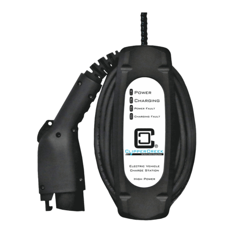
ClipperCreek LCS Series User manual
