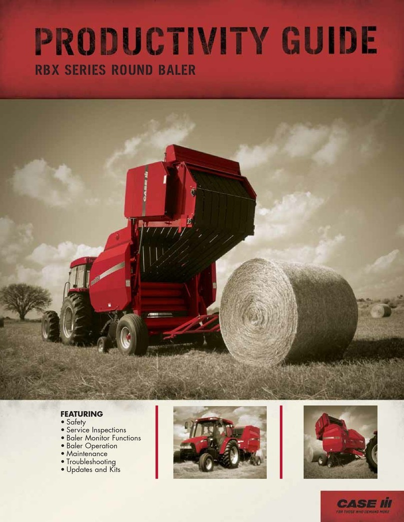
Case IH RBX443 Operating instructions

5%; 5RXQG %DOHU
5HSDLU 0DQXDO

6(&7,21 *(1(5$/ ,1)250$7,21
6(&7,21 ,03/(0(17 '5,9(/,1(
6(&7,21 +<'5$8/,& 6<67(0
6(&7,21 (/(&75,&$/ 6<67(06
6(&7,21 352'8&7 )((',1*
6(&7,21 35(66,1*
6(&7,21 7<,1*
7KH VHFWLRQV XVHG WKURXJK RXW DOO &DVH ,+ SURGXFW 5HSDLU PDQXDOV PD\
QRW EH XVHG IRU HDFK SURGXFW (DFK 5HSDLU PDQXDO ZLOO EH PDGH XS RI RQH
RU VHYHUDO ERRNV
7KH VHFWLRQV OLVWHG DERYH DUH WKH VHFWLRQV XWLOL]HG IRU WKH 5%; 5RXQG
%DOHU
5%; 5(3$,5 0$18$/
&217(176
¤ &1+ $PHULFD //&

COMPLETE CONTENTS
SECTION 00 - GENERAL INFORMATION
Chapter 1 - General Information
CONTENTS
Section Description Page
00 000 Foreword 2.....................................................................
Introduction 3...................................................................
Precautionary Statements 4.......................................................
Safety 5........................................................................
Fluid Safety 7...................................................................
Handle Fluids Safely 7........................................................
Avoid Heating Near Pressurized Fluid Lines 7....................................
Use Care Around High-pressure Fluid Lines 7....................................
Safe Service Procedures 7....................................................
Safety Decals 8..................................................................
Technical Information 12.........................................................
Hardware 12................................................................
Minimum Hardware Tightening Torques 13.........................................
Thread Locking Compounds 15................................................
Retaining Compounds 15.....................................................
Sealants 15.................................................................
Standard Torque Data for Hydraulic Tubes and Fittings 16............................
Lubrication 17..................................................................
Roller Chains 19.............................................................
Conversion Charts 21...........................................................
Ecology and the Environment 25..................................................
International Symbols 26.........................................................
Baler Components 27........................................................
Specifications 28................................................................

SECTION 31 - IMPLEMENT DRIVELINE
Chapter 1 - PTO Driveline
CONTENTS
Section Description Page
Specifications 2..................................................................
PTO Constant Velocity 2.......................................................
Overhaul 3......................................................................
Front PTO and CV U-joint 3....................................................
Disassembly 3............................................................
Inspection 6..............................................................
Assembly 6..............................................................
Installation 10............................................................
Rear PTO 11................................................................
Removal 11..............................................................
Disassembly 11...........................................................
Assembly 13............................................................
Installation 15............................................................
Shear Bolt Hub 16...........................................................
Shear Bolt Hub Bearing Balls 16...............................................
Replace 16..............................................................
Slide Collar Quick-Disconnect 17..............................................
Disassembly 17..........................................................
Replace 17..............................................................
SECTION 31 - IMPLEMENT DRIVELINE
Chapter 2 - Gearbox
CONTENTS
Section Description Page
Specifications 2..................................................................
Description of Operation 2........................................................
Overhaul 3......................................................................
Gearbox 3...................................................................
Removal 3...............................................................
Disassembly 8............................................................
Inspection 11.............................................................
Assembly 12............................................................
Installation 19............................................................

SECTION 35 - HYDRAULIC SYSTEM
Chapter 1 - Hydraulic System
CONTENTS
Section Description Page
General Procedures 2............................................................
Description of Operation 3........................................................
Overhaul 4......................................................................
Lift Cylinder 4................................................................
Removal 4...............................................................
Installation 4..............................................................
Disassembly 5............................................................
Inspection 6..............................................................
Assembly 6..............................................................
Troubleshooting 7................................................................

SECTION 55 - ELECTRICAL SYSTEMS
Chapter 1 - General Information
CONTENTS
Section Description Page
Definition of Terms 2.............................................................
Electricity 2..................................................................
Voltage 2....................................................................
Current 2....................................................................
Resistance 2.................................................................
Open Circuit 2...............................................................
Short Circuit 2...............................................................
Continuity 2..................................................................
Voltage Drop 2...............................................................
Diode 2.....................................................................
Solenoid 2...................................................................
Relay 2.....................................................................
Description of Operation 3........................................................
Protecting the Electrical/Electronic Systems
During Charging or Welding 3..................................................
Special Tools 4..................................................................
Troubleshooting 5................................................................
Test Procedure 1: Continuity Test for Open Circuits 6..............................
Test Procedure 2: Continuity Test for Short to Ground 7............................
Test Procedure 3: Resistance Test for Electrical Components 8.....................
Test Procedure 4: Voltage Measurement 9.......................................
SECTION 55 - ELECTRICAL SYSTEMS
Chapter 2 - Twine Wrapper System
CONTENTS
Section Description Page
Overhaul 2......................................................................
Electrical Control Box 2.......................................................
Replace 2................................................................
Adjustment 3....................................................................
Full Bale Alarm Switch 3.......................................................

SECTION 55 - ELECTRICAL SYSTEMS
Chapter 3 -- Lights and Connectors
CONTENTS
Section Description Page
Overhaul 2......................................................................
Wire Harness Connector 2.....................................................
9-Pin Connector 2............................................................
Round Connector 3...........................................................
Gray Rectangular Connector 5.................................................
Light Plug 6..................................................................
Power Plug 7................................................................
Light Module 8...............................................................
Baler Lights Wiring Diagram 9.....................................................
SECTION 60 - PRODUCT FEEDING
Chapter 1 - Standard Pickup Assembly
CONTENTS
Section Description Page
Overhaul 2......................................................................
Finger 2.....................................................................
Replace 2................................................................
Cam Bearing 2...............................................................
Replace 2................................................................
Slip Clutch 3.................................................................
Replace 3................................................................
Pickup 5....................................................................
Removal 5...............................................................
Installation 6..............................................................
Cam Track 6.................................................................
Disassembly 6............................................................
Assembly 8..............................................................
This section covers the normal maintenance and repair, as well as complete rebuild, of the standard pickup.

SECTION 62 - PRESSING
Chapter 1 - Floor Roll
CONTENTS
Section Description Page
Sectional Views 2................................................................
Overhaul 3......................................................................
Floor Roll 3..................................................................
Removal 3...............................................................
Inspection 4..............................................................
Assembly 5..............................................................
SECTION 62 - PRESSING
Chapter 2 - Starter Roll
CONTENTS
Section Description Page
Sectional Views 2................................................................
Overhaul 3......................................................................
Starter Roll 3................................................................
Removal 3...............................................................
Installation 4..............................................................

SECTION 62 - PRESSING
Chapter 3 - Apron Rolls
CONTENTS
Section Description Page
Description of Operation 2........................................................
Belt Tension 3................................................................
Overhaul 4......................................................................
Drive Roll 4..................................................................
Removal 4...............................................................
Inspection 5..............................................................
Installation 5..............................................................
Adjustment 6.............................................................
Idler Rolls 7..................................................................
Rolls 14, 18, 19, 20 and 23 8...................................................
Removal 8...............................................................
Roll 21 8....................................................................
Removal 8...............................................................
Inspection (All Idler Rolls) 10...............................................
Assembly 11.............................................................
Rolls 14, 19 and 20 11.....................................................
Roll 21 11................................................................
Rolls 18 and 23 12.......................................................
Take-Up Arm 13.............................................................
Disassembly 14..........................................................
Inspection 15............................................................
Assembly 15............................................................

SECTION 62 - PRESSING
Chapter 4 -- Apron Belts
CONTENTS
Section Description Page
Sectional Views 2................................................................
Troubleshooting 3................................................................
Belt Failure Analysis 3........................................................
Overhaul 7......................................................................
Belt Tension Removal 7.......................................................
Laced Belt 7.................................................................
Removal 7...............................................................
Replace 8................................................................
Installation 11.............................................................
Belt Tracking 13.............................................................
SECTION 62 - PRESSING
Chapter 5 -- Sledge Rolls
CONTENTS
Section Description Page
Sectional Views 2................................................................
Overhaul 3......................................................................
Follower Roll 3...............................................................
Removal 3...............................................................
Installation 4..............................................................
Pivot Roll Sledge Assembly 6..................................................
Removal 6...............................................................
Disassembly 10..........................................................
Installation 11.............................................................
Table of contents
Other Case IH Lawn And Garden Equipment manuals
Popular Lawn And Garden Equipment manuals by other brands

Vertex
Vertex 1/3 HP Maintenance instructions

GHE
GHE AeroFlo 80 manual

Millcreek
Millcreek 406 Operator's manual

Land Pride
Land Pride Post Hole Diggers HD25 Operator's manual

Yazoo/Kees
Yazoo/Kees Z9 Commercial Collection System Z9A Operator's & parts manual

Premier designs
Premier designs WindGarden 26829 Assembly instructions

AQUA FLOW
AQUA FLOW PNRAD instructions

Tru-Turf
Tru-Turf RB48-11A Golf Green Roller Original instruction manual

BIOGROD
BIOGROD 730710 user manual

Land Pride
Land Pride RCF2784 Operator's manual

Makita
Makita UM110D instruction manual

BOERBOEL
BOERBOEL Standard Floating Bar Gravity Latch installation instructions


