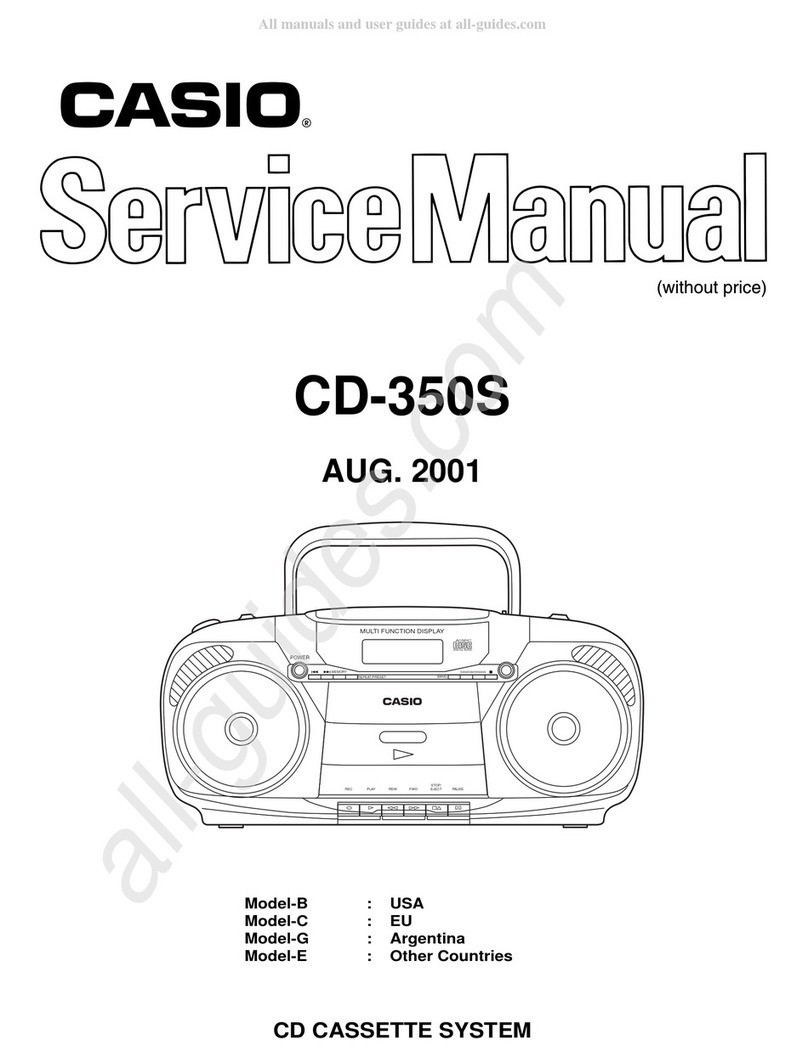
Casio CD-350S User manual

CD CASSETTE SYSTEM
CD-350S
AUG. 2001
Model-B : USA
Model-C : EU
Model-G : Argentina
Model-E : Other Countries
POWER
BAND
PLAYREC REW FWO EJECT PAUSE
STOP/
MEMORY REPEAT/PRESET RANDOM/REMAIN
MULTI FUNCTION DISPLAY
COMPACT
DIGITAL AUDIO

CONTENTS
SPECIFICATIONS--------------------------------------------------------------------------------- 1
BLOCK DIAGRAMS ------------------------------------------------------------------------------ 2
ADJUSTMENTS ----------------------------------------------------------------------------------- 4
CASSETTE MECHANISM --------------------------------------------------------------- 4
TUNER ---------------------------------------------------------------------------------------- 6
CD TROUBLESHOOTING ---------------------------------------------------------------------- 8
PCB LAYOUT------------------------------------------------------------------------------------- 18
WIRING DIAGRAMS---------------------------------------------------------------------------- 20
SCHEMATIC DIAGRAMS --------------------------------------------------------------------- 21
EXPLODED VIEWS ----------------------------------------------------------------------------- 23
PARTS LIST--------------------------------------------------------------------------------------- 26

— 1 —
SPECIFICATIONS
CD PLAYER
Type ..............................................................Compact disc player with optical pick up
Number of channels......................................2 (stereo)
Frequency response .....................................20 Hz - 20 kHz, ±3 dB
Dynamic range..............................................70 dB
Total harmonic distortion...............................0.1 % (1 kHz)
S/N ratio ........................................................70 dB
Wow and flutter .............................................Unmeasurable
RADIO
Frequency range
AM ......................................................530 – 1710 kHz
FM.......................................................87.5 – 108 MHz
Antenna
AM ......................................................Ferrite-bar antenna
FM.......................................................Telescopic antenna
TAPETape speed ...................................................4.75 cm/sec.
Track format..................................................4-track, stereo
Wow and flutter .............................................0.2 % (WRMS)
S/N ratio ........................................................35 dB
GENERAL
Power consumption ......................................AC 18 W
Output power ................................................1.3 W + 1.3 W (10 % THD)
Speaker.........................................................102 mm, 8 ohms ×2
Dimensions ...................................................395 ×175 ×175 mm (WMD)
Weight...........................................................3.6 kg (with batteries)
Accessories...................................................AC power cord
User’s guide
* Specifications are subject to change without notice.

— 2 —
BLOCK DIAGRAMS
M
M
AM ANT.FM ANT.
FM RF.
L102
AM OSC.
T103
IC101
TA2104AN
FM OSC.
L103
FM/AM IFT.
T102
IC904
LPF
BA4510
TUNER MUTE
Q118, Q119
MUTE
Q904, Q905
REGULATOR
Q120
CN103
AUDIO MUTE
Q909, Q910
REGULATOR
Q403
+8V
POWER ON/OFF
+12V
Q402
REGULATOR
Q903
+5V
DIGITAL SIGNAL
PROCESSOR
IC901
TC9284BF
U-COM
IC701
TC9314F-043
LCD DISPLAY
X901
16.9344MHz
CF701
75KHz
TO AUDIO AMP. BLOCK
KEY CONTROL
DOOR SWITCH
SLT. SWITCH
DISC MOTOR
SLED MOTOR
DISC
CN901
CN702
CN902
PICKUP
MUTE
LAMP
CD
VCC1
TUNER
TAPE
GND
VCC2
TO AUDIO AMP. BLOCK
+5V
LAMP CONTROL
Q406
MOTOR AND
ACTUATOR
DRIVER
IC903
SIGNAL SERVO
AMP.
IC902
LASER
DRIVER
Q901
LAMP
10V 40mA X3

— 3 —
AC BIAS OSC.
T801
(80KHz)
REC/PLAY
AMP.
IC201
AUDIO AMP.
Q205, Q206
VOLUME
VR201
MUTE
Q301, Q302
POWER AMP.
IC301
LA4227 R. SPEAKER
PHONES
REGULATOR
+5V
Q207
REC
/PLAY
SWITCH
TAPE
MUTE
Q201, Q202 FUNCTION
SWITCH
SW301
RECTIFIER
D1101 ~ D1104
IN4001
POWER
TRANSFORMER
BATTERY
UM 1X8
DC: 12V
AC SOCKET
SWITCH
CN202 CN203
LAMP
MUTE
TU R/L CH.
VCC1
CD
TUNER
TAPE
GND
VCC2
+5V
R/P
R. CH
R/P HEAD
L. CH
CN201

— 4 —
ADJUSTMENTS
CASSETTE MECHANISM
General Remarks
• Before attempting to adjust the mechanism, wipe clean all tape-contacting surfaces (pinch roller, REC/PB
head, erase head, and capstan), as well as the contact surfaces of the driving parts (motor pulley, flywheel,
pulley, belt, and clutch assembly), with a piece of soft cloth moistened with denatured alcohol. Grease stains
may cause trouble.
• Never use a magnetized screwdriver for head adjustment.
Equipment Required
• Oscilloscope
• Frequency counter
• Screwdriver (Plastic type)
• Test tapes MTT-113C (TEAAC) or TCC-111N (TEAC)
Head Azimuth Adjustment (Figures 1 and 2)
Set
Headphone jack
Note: Mode Switch is X--Y position.
B
A
Step
1
Setting
Play the test tape 8 KHz
Position (MTT-113C)
Adjust
Azimuth screw
(Figure 2)
Result
Obtain the maximum amplitude
(A: Maximum) (B: Minimum)
Figure 1
Figure 2
Adjust Screw P/R Head

— 5 —
Tape Speed Adjustment (Figures 3 and 4)
Step
1
Setting
Play the test tape
(MTT-111N)
Adjust
Motor screw
(Figure 4)
Result
Frequency counter reading should be
3000 Hz (2940 ~ 3060).
Figure 3
Frequency CounterSET
Headphone Jack 3000
Figure 4
Motor
Screw

— 6 —
TUNER
General Remarks
• When aligning the range and adjusting tracking, proceed with alignment in a sequence of AM--FM.
• Use a screwdriver with a plastic grip for all alignments.
Equipment Required
• AM signal generator (AM SG)
• Loop antenna
• Output meter
• Oscilloscope
• FM signal generator (FM SG)
• Screwdriver (Plastic type)
• Dummy load 32 ohm
AM SG Set
GND
60 cm Bar
Antenna
Output meter Oscilloscope
Headphone jack
Dummy load 32 ohm
MW Alignment (Figures 5)
AM IF Alignment (Figures 5)
Step Alignment
IF calibration
Tuning dial
setting
999 KHz/
1000 KHz
Remarks
Obtain sine-wave and
maximum amplitude
Frequency of
signal generator
450 KHz
Adjustment
T102
Max.
Max.
Step
1
2
1
2
3
Alignment
Tuning range
calibration
Adjustment of
tracking
Tuning dial
setting
Low end
High end
600 KHz/
612 KHz
1400 KHz/
1404 KHz
Remarks
Confirm : 1.4 V ±0.05 V
Confirm : 7.5 V ±0.4 V
Obtain sine-wave and
maximum amplitude
Frequency of
signal generator
522/530 KHz
1620/1710 KHz
600/612 KHz
1404/1400 KHz
Adjustment
T102
—
MW COIL
(Bar Antenna)
CT103
Repeat the above adjustment
Figure 5

— 7 —
FM Alignment (Figures 6)
FM IF Alignment (Figures 6)
Step Alignment
IF calibration
Tuning dial
setting
98.1 MHz
Remarks
Obtain sine-wave and
maximum amplitude
Frequency of
signal generator
10.7 MHz
Adjustment
(Non-
adjustment)
Max.
Max.
Step
1
2
1
2
3
Alignment
Tuning range
calibration
Adjustment of
tracking
Tuning dial
setting
Low end
High end
90.1 MHz
106.1 MHz
Remarks
Confirm : 20 V ±0.1 V
Confirm : 6.5 V ±0.2 V
Obtain sine-wave and
maximum amplitude
Frequency of
signal generator
87.5 MHz
108 MHz
90.1 MHz
106.1 MHz
Adjustment
L103
—
L102
CT101
Repeat the above adjustment
FM SG
GND
FM ANT.R2
R1 FM GND
Output meter Oscilloscope
Headphone jack
Dummy load 32 ohm
R1 = Output impedance of FM SG
R2 = 75 ohm - R1/2 ohm
SetFM dummy load
Figure 6

— 8 —
CD TROUBLESHOOTING
Open the CD door and set the
function switch for CD position.
Is “00” display
on LCD?
Is total track
number displayed?
Is the audio signal
present at the output
terminals?
Can a selected
music be searched
smoothly?
No
(See page9)
No
No
No
1
2
3
4
Yes
Yes
Yes
Yes
Load a disc and close the CD door.
Press “ / ” button.
Press “ ” or “ ” button.
OK
(See page17)
(See page16)
(See page9)

— 9 —
1. At power on, “00” is not displayed.
2. Total track number is not displayed.
Note : Figure 7 is normal eyepattern.
pin 1 FO IC902 (RFO) pin 3 FO IC902 (VREF)
1
Is + 5V lines
normal (for IC902)?
Does
16.93MHz clock pulse appear
at pin 78/79 of IC901?
No l Check Q903.
l Check pins 26 and 58.59.77 of IC901.
No l Check X901.
l Check circuit around X901 and IC901.
Yes
Yes
l Check soldering and circuit around IC901.
l Check LCD.
l Check wire connector.
2
How long does it take until “00 00:00” is
displayed after the CD door has closed?
Less than 16 sec. More than 16 sec.
A B
(See page10) (See page13)
1.0 Vp-p
~
1.5 Vp-p
Figure 7

— 10 —
A
Does the Laser emit?
Does the lens
move up and down?
Is the
waveform at pin
35 (FEO) of IC902 like that
shown
in figure 9?
Is the waveform
at pin 1 FO IC902 like that shown
in figure 8?
No
No
A1
A2
Yes
Yes
Yes
Yes
Load a disc and close the CD door.
Then check the following.
No
No
l Check wire connector from
pickup.
l Check circuit around pins
1~5 and 46~48 of IC902.
l Check circuit around
pins 30~42 of IC902.
l Check circuit around IC901, IC902 and
IC903.
(See page12)
(See page11)
Figure 8
Figure 9
>1.5 V
>1.5 V
2-A Note : Open the CD door and set the door switch for “on” position. Check the radiation power with
an optical power meter or by watching the radiation through the lens or the pickup unit at a
minimum distance of 30cmfrpm the from pickup.
RFO-Vref
RFO-Vref

— 11 —
2-A1
A1
Is Q901
emitter 5V?
(Play)
Is waveform
at pin 21 (SEL) of IC902 like that
shown in figure 10?
No l Check Q901.
No l Check circuit around
IC901 and IC902 (SEL).
Yes
Is waveform
at base of Q901 like that
shown in figure 11?
No l Check circuit around
pins 21 and 45 of IC901.
Yes
Yes
l Check contact 15P flat cable.
l Check pickup.
(GND) (GND)
2.5 V
0 V
3 V
0 V
Figure 10 Figure 11

— 12 —
2-A2 A2
Is Q403
emitter 8V?
Is waveform
at C964 4.7UF (FSO) like that
shown in figure 12?
No l Check circuit around Q403.
No l Check circuit around pin
16 (FSO) of IC902.
l IC902 is defective.
Yes
Is
waveform at pins 21 to 23
of IC903 like that shown
in figure 13?
Yes l Check circuit around
pins 20~23 of IC903.
Yes
Yes
l Check 15P flat cable.
l Check focus coil of pickup
(DC resistance : 8 Ω).
Vref 0.2 V
Vref 2.5 V
Figure 12 Figure 13

— 13 —
2-B
B
Does the
disc motor rotate? Yes
No
No
Is waveform at pin
24 (DMEO) of IC902 like that
shown
in figure 14?
Is waveform at pins
14 to 16 of IC903 like that
shown
in figure 15?
l Check circuit around pin
24 of IC902.
l Check circuit around pins
14 to 16 of IC903.
l IC902 is defective.
Yes
Yes
l Check sled motor (DC resistance :12 Ω).
l Check wire connector.
B1
(See page14)
Vref 4 V
Vref 4 V
Figure 14 Figure 15

— 14 —
2-B1, B2
B1
Is PSET switch
circuit normal? Yes
Yes
Is waveform at
pin 54 PU-INNER of IC701 like
that shown in figure 16?
lCheck PU-INNER switch.
lCheck wire connector.
lCheck circuit around pin 54 of
IC701.
No
B2
Does gear
and mechanism of disc motor
operate normally? B3
Yes
Is waveform at
pin 26 (FMSO) of IC902 like that
shown in figure 17?
No
Is waveform
at pins 9 to 11 of IC903 like that
shown in figure 18?
No
No
Yes
Yes
lCheck disc motor (DC resistance :12 Ω).
lCheck wire connector.
lCheck operation of gear.
lCheck circuit around pin 26 (FMSO) of IC902.
lCheck circuit around pins 9 and 11 of IC903.
lIC902 is defective.
(See page15)
GND
5 V
V
ref
0.4 V
Vref
4.5 V
Figure 16
Figure 17
Figure 18

— 15 —
2-B3
Is waveform at
pin 30 (TS20) of IC902 like that
shown in figure 21?
Yes
Is waveform at
pins 2 and 4 of IC903 like that
shown in figure 22?
Yes
Yes
l Check circuit around pins 30~40
of IC902.
l Check circuit around pins 1~5 of
IC903.
l IC902 is defective.
l Check flat cable.
l Check tracking coil of pickup
(DC resistance : 8Ω).
No
No
No
Is waveform at
pin 35 (TSO) of IC902 like that
shown in figure 20?
Yes
B3
Is waveform
at pin 1(RFO) of IC902 like that
shown in figure 19?
No l Check circuit around pins 1~5
and 41~44 of IC902.
1.5
Figure 19 Figure 20
0.1
1.5
Figure 21 Figure 22

— 16 —
3. No present at R939 (R ch) and R940 (L ch) audio signal.
3
Does audio
signal appear at pins 1 and 8
of IC904?
No
Yes
l Check pins 1~7 of IC901.
l Check circuit around pins 1~8 of IC904.

— 17 —
4. Selected music cannot be searched smoothly.
4
Is waveform
at pin 35 (TSO) of IC902 like that
shown in figure 23?
No
No
No
Is waveform at pins
36~37 and 29 of IC701 like that
shown
in figure 24?
Yes
Is waveform at pins
2 and 4 of IC903 like that shown
in figure 25?
Yes
l Check R-SKIP and F-SKIP.
l Check wire connector (CN902).
l Check pins 29 and 36~37 of IC701.
l Check voltage of IC903.
l Check flat cable.
Press the play key.
(PAUSE)
l Check 100mV PP waveform at pins
3 and 8 of CN901.
l Check pins 4 and 5 of IC901.
l Check pickup.
Yes
l Check gear and mechanism of sled motor.
l Check lens of pickup.
Press the “ ” or “ ” key.
Figure 23 Figure 24 Figure 25
VREF
VREF-TEO
A
BA=B
A+B>1.3
5 V
0 V
2.5 V

— 18 —
PCB LAYOUT
Q109
Q126
Q106
C178
C170
C141 VD105
JP104
C179
C152
R405
R407
C958
C402
C942
R954
LED+
R942
R943
C936
R950 R704
R163
R159
JP913
JP916
JP918
R978 JP710
JP6
JP717
JP716
JP715
JP711
R744
D707
D708
D709
D704
D703
D706
D712
D713
D710
R741
JP929
CN902 JP930
R977 R743
R908
R907
JP914
R957
C976
Q905
C940
C938
R970
C943
R938
R941
R952
R953
R948
JP909
JP907
C913
C919
R951
C937
R949
R910
JP947
JP946
JP945
JP943
JP942
JP941
JP940 JP922
JP921
JP923
JP924
JP925
IC903
JP939
JP938
VR903
JP937
JP936 JP926
R935
C980
C973
R937
R975
C925
R906 R921
R920
R916
R923
C903
R912
C944
C911
R911
R913
R904
JP949
R902
RFO
C927
R936
Q904
D702
D401
C151
C981
L103 L103
C104
C127
C117
C106
D102
D101
C101
CF105
JP1
C114
FM DSC+
R124
R123
R182
R185
R184
R127
C109
R183
R143
Q125
C156
C161
C160
Q119
D112
C171
C172
C720
C159
R133
R115
R147
R134
JP108
JP715
REMAIN
JP116
JP117
R993
R120
R135
C119
R173
CN101
JP4
JP3
JP105
D718
R176
R179
C711
C717
R178
R738
JP173
JP5
JP706
R708
C713 Q703
Q402
Q907
R403
R161
R410
R939
R940
R413
R250
C169
Q401
Q408
Q908 R955
R956 R958 R960
R959
R712
R979
R976
C977
D705
C719
C972 DM-
DM+
SLT
GND
FM+
FM-
F-
F+
LD
PD
A
D
E
COM
T+
T-
LG
UR
C
F
B
C975
C984
R997
D711
JP972
JP912
JP911 JP915
JP910
JP708
JP919
JP920
JP709
D715
D716
R742
C969
U-D
D714
REPEAT
MEMORY
F-SKIP
R-SKIP
JP712 ON/OFF
SENSOR
U+
SW.
CN703
DOOR SW.
R914
C953
C931
C987
C935
C712
R711 C718
R735
R739
R401
R402
R982
R980
R981
D504
C952
C951
C950
IC901
D503
L701
C986
GND
YY
X
X
BA
CF701
C702
C701
FM DSC+
D701
CN103
CN706
RANDOM
PLAY/PAUSEK
BAND
C705
Q118
STOP
A
C128
C132
R180 Q116
R175
R174
Q102
IC102
C155
C131
C715
R996
R408
C716
R404
R995R160
Q910
Q403
Q404
Q405
R406
R709
C988
D902
C941 Q903
C918 C959
R961 R962
C917
IC902
C901
JP944
JP951
JP934
JP931
R990
R966
R963
R965
C902
C960
C914
C964
C926
C974
IC701
C971
CN901
R973
R972
R964 R974
C965
C970
TEO
R915R905
C961
R901 R962 C963 C904
R925 R926
25
C921
R922
C966
C908
R927 R930
R931
C982
R968
R928
C933
C930
L903
R967
VR902
C983 C915 Q901 C968
JP950
R934
VR901
Q406
R969 R944
R945
C929
C954
R946
R947 C934
C949
C939
JP908
FB901
X901 R903 JP948
C910
C907
R909
R919
C906
C923
C955
IC 904
C956
U+
U-
D403
D402
L702 L902
L901
D210
Q909
C153
D109
D110
D111
D209
D211
D901
C989
R991
JP119
JP401
JP904
CN702
JP201
JP902
JP903
JP901
R710
C985 C957
JP118
R992 Q704
C714
R714
R118
C706
C710
C703
C704
C708
C707
R737
R713
R715
R716
R717
R718
LED-
JP701
JP702
JP906
C721
R703
R740
C709
R705
R719
JP704
JP2 R706
JP905
R707
R177
D107
D108
R409
C163D404
C990
C122
C113
JP102
R116
R132
T103 R146
C112
C116C108
T102
JP7 CF101
CF103
CF102
Q120
R166
D113
JP8
JP102
JP111
C118
L102 L101
L106
L107
C133R186
C105
C107
C401 C945 C947
2470114E.PCB 248-247801-104 PCB FOR SAYO CD MECH. AND TA2104AN 5-Sep-2001 14:16:17
C948
C110
FM ANT
C103
C102
C115
C121
C111
JP123
VD102
Q110
R121
R181
GND
C139
C135
MW/R
MW/W
JP103
MW/B
MW/B
R144
R104
R101
CT101
CT103
VD103
VD101
R131
C130
R122
C120
R170 R994
D717
LCD701
MATESTAR
248-247801-104
CN704
SK/10K
MAIN PCB
Other manuals for CD-350S
1
Table of contents
Other Casio Cassette Player manuals