— 1 —
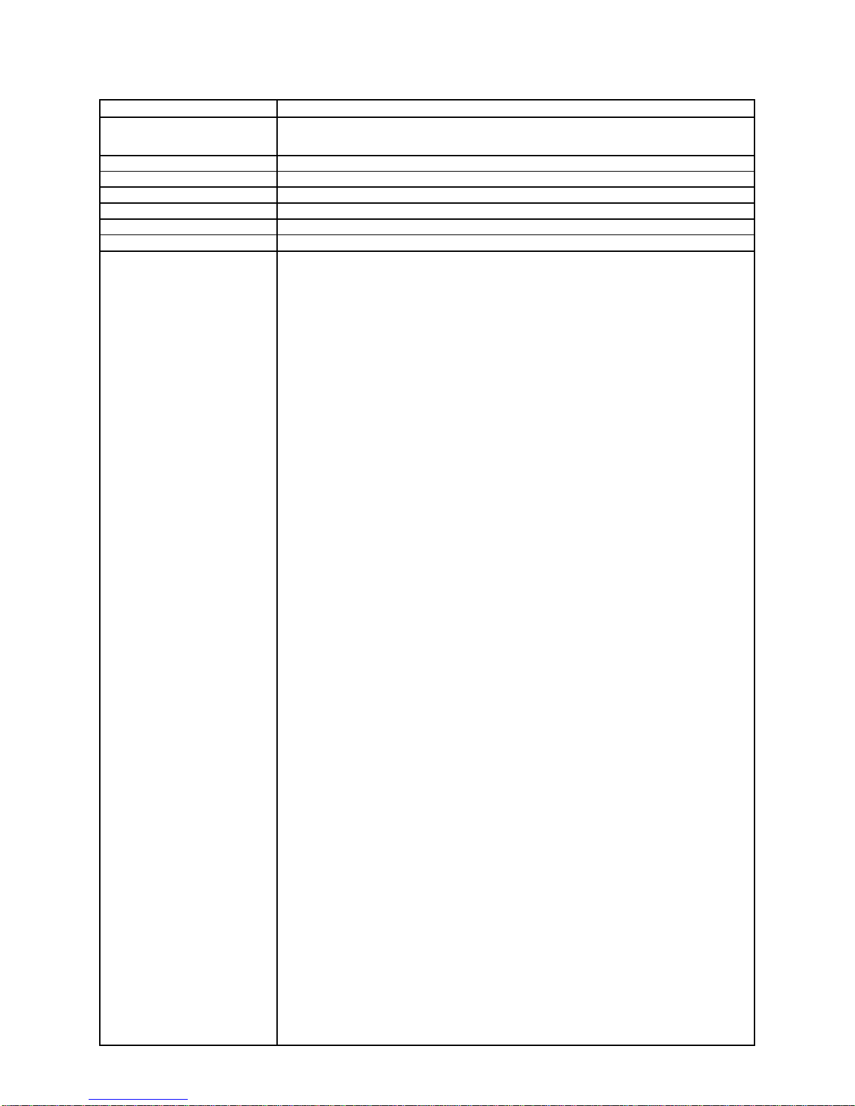
1. SPECIFICATIONS: MODULE QW-3042
Battery CTL1616 (Storage battery)
Note: Use CTL1616 only. Other storage battery or CR1616 can cause
damage to the watch.
Battery life Approx. 5 months (from full charged condition)
Current consumption 1.764 µA maximum
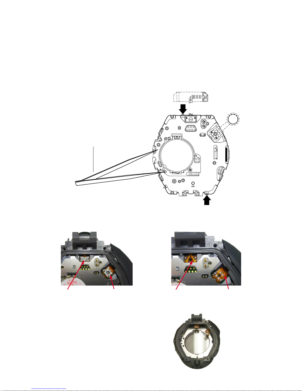
Alarm system Piezo plate on Cover/Back
Accuracy ±15 sec./month
Accuracy setting system Trimmer capacitor
Accuracy checking See page 8
Functions: • Electro-luminescent backlight
Full auto EL light, afterglow
• Solar powered
• Low-temperature resistant (–10°C)
• Digital compass
Measures and displays direction as one of 16 points
Measuring range: 0 to 359°
Measuring unit: 1°
20 seconds continuous measurement
Graphic direction pointer
Bidirectional calibration and northerly calibration function
• Altimeter
Measuring range: –700 to 10,000 m
Measuring unit: 5 m
Auto memory measurements (up to 40 records, each including altitude, month, data, time)
High Altitude / Low Altitude Memory
Cumulative Ascent / Descent Memory
Relative Altitude Display
Altitude Tendency Graph
Altitude Differential Graphic
Altitude alarm
• Barometer
Display range: 260 to 1,100 hPa
Display unit: 1 hPa
Atmospheric pressure tendency graph
Atmospheric pressure differential graphic
• Thermometer
Display range: –10 to 60°C
Display unit: 0.1°C
• Duplex LC display
• World time
29 time zones (30 cities), city code display, daylight saving on/off
• 1/100-second stopwatch
Measuring capacity: 9:59'59.99"
Measuring modes: Elapsed time, split time, 1st-2nd place times
• Countdown timer
Measuring unit: 1 second
Countdown range: 60 minutes
Countdown start time setting range: 1 to 60 minutes (1-minute increments)
Others: Auto-repeat, progress beeper
• Daily alarms
5 independent daily alarms
• Hourly time signal
• Battery power indicator
• Power save function (automatically disables LCD if the watch is left in the dark for approximately 60 to 70
minutes, and sensor measurements if the watch is left in the dark for six or seven days)
• Auto-calendar (to year 2099)
• 12/24-hour format
• Regular timekeeping: Hour, minutes, seconds, pm, month, date, day
• Time calibration signal reception
Auto receive
Manual receive
Last date/time received display
• Receivable Time Calibration Signals
Mainflingen, Germany (Call Sign: DCF77, Frequency: 77.5kHz)
Rugby, England (Call Sign: MSF, Frequency: 60kHz)
Fort Collins, Colorado (Call Sign: WWVB, Frequency: 60kHz)
Fukushima, Japan (Call Sign: JJY, Frequency: 40kHz)
Fukuoka/Saga, Japan (Call Sign: JJY, Frequency: 60kHz)
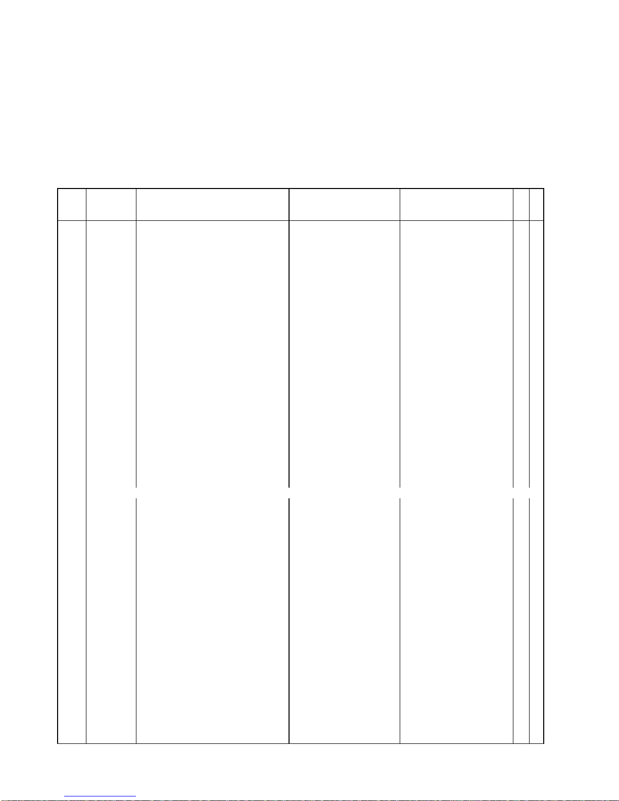
Item Detail


 User manual")