Non contractual document - Cassese France®- Document non contractuel
1 - PRESENTATION
A) INTRODUCTION
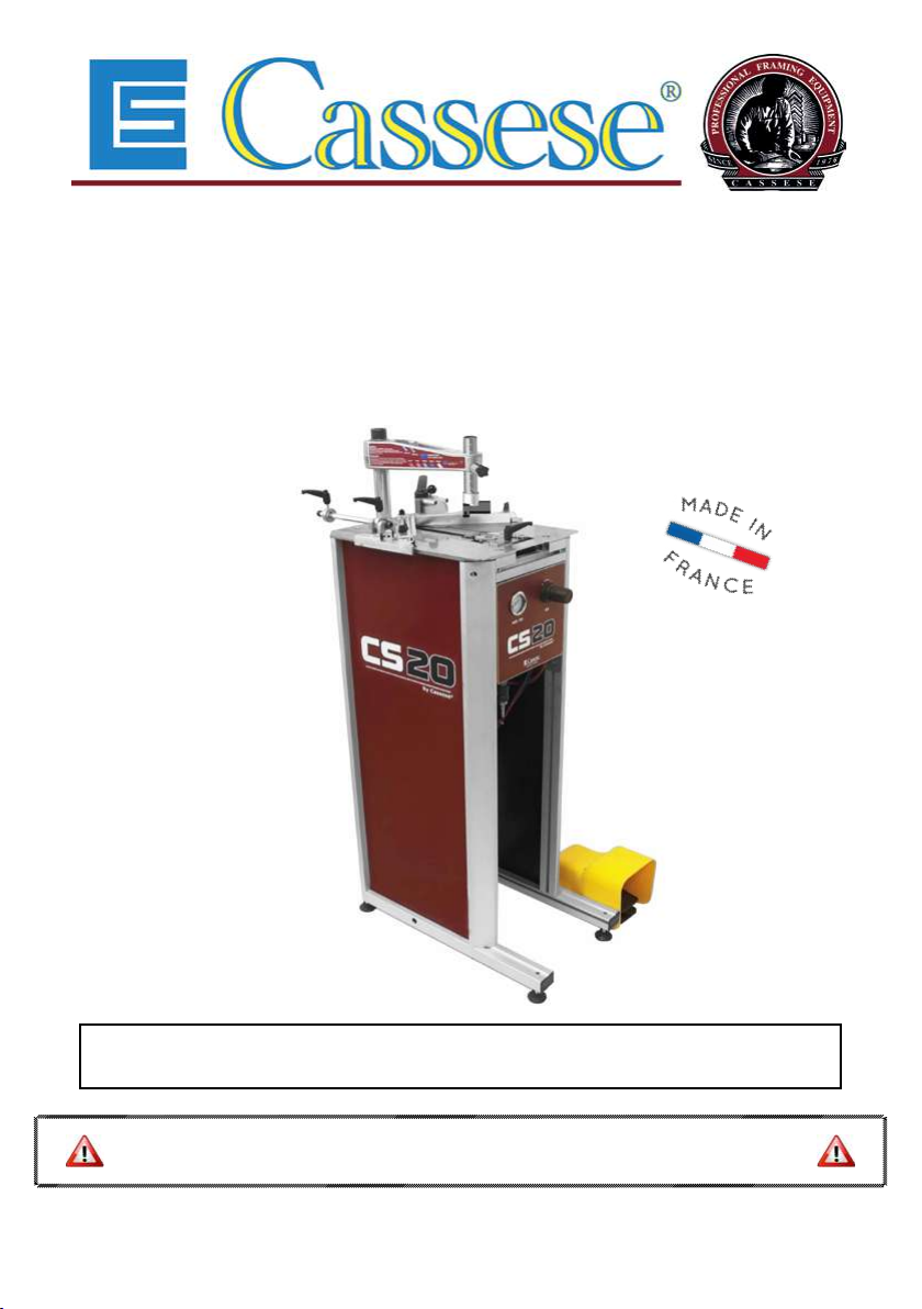
Thanks for having purchased the CS20 CART underpinner and for your trust in Cassese®
and manufacturing highest quality underpinners, for which we are world-famous. The
Joining operation is carried out by using Genuine Cassese®Cartridge Wedges, specially
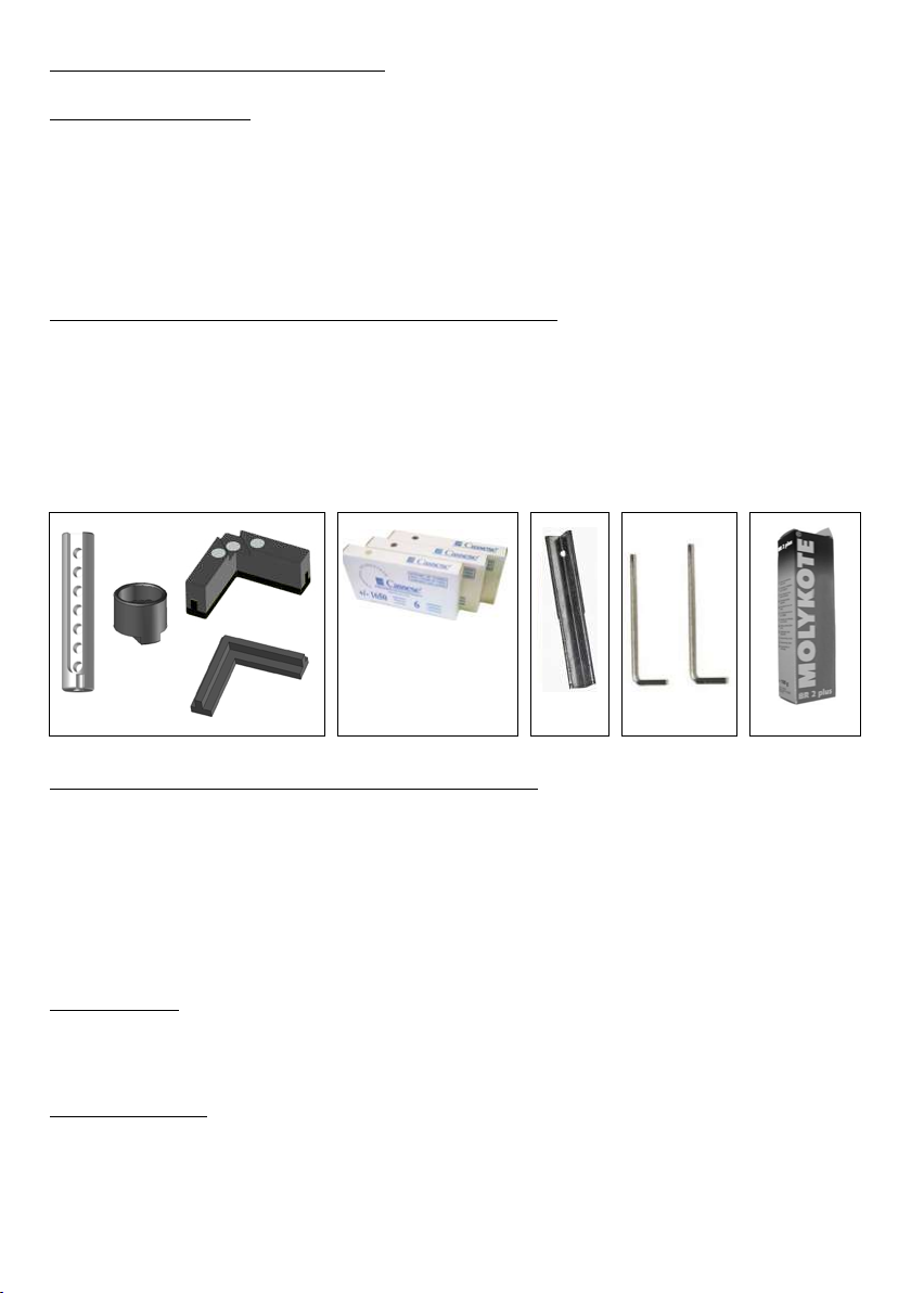
B) ACCESSORIES SUPPLIED WITH THE MACHINE
A) 1 Magnetic adjustable rod clamp + 1 Chevron holder + 1 Magnetic chevron clamp +
1 Chevron rubber.
C) 1 Wedge driver blade for using CASSESE®Genuine Cartridge Wedges.
D) 1 Allen Key 2.5 mm + 1 Allen Key 3 mm.
E) 1 Grease Tube.
C) TECHNICAL SPECIFICATIONS OF CS20 CART
1/2)
Cassese®Genuine Cartridge Wedges sizes: 5, 7, 10, 12 and 15 mm.
3 wedge types : Softwood, Hardwood & MDF. Use only Cassese®Genuine Cartridge Wedges.
3/16
1/4).
D) OPTIONS
E) GUARANTEE
One year guarantee for parts and labour against manufacturing defects. Wear parts and
those damaged as a result of non compliance with the instructions of the present manual are
parts.
2
A B CDE
Z1879
Z506 Z1896Z1882
Z21525
Z21524
+
+
Z24703
Z26999