Castaldi Lighting D68-Kea Instruction Manual

MI/2054 - 3aed. ITA - 07/2017 prodotto rispondente ai requisiti previsti
dalle Direttive Comunitarie Europee
NOTA BENE: le presenti istruzioni di montaggio informano l’utilizzatore sulle corrette modalità di manutenzione e ricambio delle lampade. E’ vietata qualsiasi manomissione e/o
trasformazione dell’apparecchio che deve essere installato ed utilizzato così come fornito ed in conformità delle Norme Impianti Nazionali. Installazioni non conformi fanno decadere
ogni forma di garanzia, l’azienda non risponde dei danni causati da un errato montaggio. L’INSTALLAZIONE DEVE ESSERE EFFETTUATA DA PERSONALE QUALIFICATO.
istruzioni di montaggio - manutenzione
1
D68-Kea facade singola/doppia emissione
IP65
Classe I
isolamento semplice:
è richiesta la terra
di protezione
Apparecchio totalmente
protetto contro la polvere
e contro getti d’acqua
provenienti da ogni
direzione
Nota: attrezzi, viti, rondelle e tasselli non sono inclusi
ATTENZIONE
Prima dell’installazione ed
in caso di manutenzione
togliere la tensione.
1
2ALLENTARE I GRANI E LE VITI DELL’APPARECCHIO
ATTENZIONE: SCOLLEGARE
IL FASTON DI TERRA
POSIZIONATO SUL COPERCHIO
3
CAVO AC
LASCIARE UN’ABBONDANZA DI CAVO PER POTER
EFFETTUARE LE CONNESSIONI ELETTRICHE
DIMENSIONI DELL’APPARECCHIO
CAVO DI TERRA
DEL COPERCHIO
La sorgente luminosa contenuta in questo apparecchio deve essere sostituita solo dal costruttore o dal suo servizio di
assistenza o da personale altrettanto qualificato.
ATTENZIONE MANUTENZIONE
E’ essenziale effettuare una periodica ed efficiente pulizia del vetro e della superficie esterna dell’apparecchio su cui
non debbono formarsi depositi di terra e sporcizia. Tali depositi provacano infatti pericolosi surriscaldamenti impedendo
la corretta emissione di luce e la corretta dissipazione termica.
VERSIONE LED:
ATTENZIONE:
Per l’installazione in esterni è obbligatorio utilizzare cavo tripolare flessibile in gomma
neoprene tipo H07RN-F (EN60598-1). Il diametro del cavo deve essere compreso
tra 6 e 12 mm. Non sono ammessi cavi in PVC con guaina esterna in PVC o comunque
diversi da quello qui precisato. Il cavo non è incluso con l’apparecchio.
CAVO DALI
O CAVO LOOPING
(SE PRESENTI)
x4 SVITARE LE VITI
155
260 43
Fori fissaggio
apparecchio
Fori fissaggio
apparecchio
Fori per impianto
elettrico Ø19
FISSARE LA PIASTRA POSTERIORE ALLA PARETE
USANDO VITI,TASSELLI E RONDELLE
40
3,50
9,50
150
190
INTERASSI DI FISSAGGIO
Sostituire i vetri di
protezione se danneggiati.
Contattate noi o uno dei
nostri rivenditori.
è vietato lo smaltimento come rifiuto urbano
è obbligatoria la raccolta separata a fine vita del prodotto
“Consorzio di appartenenza RAEE: Ecolight.
Registro Nazionale dei Produttori N°: IT08010000000166”
Versioni
WP (Kg)Codice
D68/F1-... 10 2,1
D68/F1-...HP 16 2,1
D68/F2-... 12 2,1
x4 x4
Nell’installazione forare e utilizzare tasselli, viti e
rondelle adeguate al tipo di supporto considerato
x4
Ø 8mm
5
INCLUSA
Superficie Calda.
NON TOCCARE.
Lasciare raffreddare
prima di maneggiare.
ATTENZIONE
Caratteristiche apparecchio e significato simboli in etichetta:
Controllo qualità: In caso di reclamo mettersi in contatto con la nostra azienda o con la nostra organizzazione di vendita citando l’ordine di acquisto e il numero
di matricola che contrassegna l’apparecchio. / Modifiche tecniche sono soggette a cambiamenti senza preavviso!

MI/2054 - 3aed. ITA - 07/2017 prodotto rispondente ai requisiti previsti
dalle Direttive Comunitarie Europee
istruzioni di montaggio - manutenzione
2
D68-Kea facade singola/doppia emissione
INSERIRE IL CAVO AC NELLA MEMBRANA A TENUTA
ASSICURARLO AL FERMACAVO ED EFFETTUARE LE
CONNESSIONI ELETTRICHE RISPETTANDO LE POLARITA’
6A
6B 6C
4
POSIZIONARE
L’APPARECCHIO SULLE
STAFFE AUSILIARIE
A.
ATTENZIONE: SEGUIRE I PASSAGGI ILLUSTRATI
PER GARANTIRE IL GRADO IP
5APRIRE LA MEMBRANA DEL PASSAFILO E
INSERIRE IL CAVO
B.
NON TOCCARE
LE SCHEDE LED
CAVO AC
CAVO DI LOOPING O
DALI (SE PRESENTI)
CAVO AC
CAVO DI TERRA
DEL COPERCHIO
CAVO DI TERRA
DEL COPERCHIO CAVO DI TERRA
DEL COPERCHIO
CAVO DALI (SE PRESENTE)
CAVO LOOPING (SE PRESENTE)
CAVO DI TERRA
DEL COPERCHIO
CONNESSIONI ELETTRICHE LOOPING
(SE PRESENTE) CONNESSIONI ELETTRICHE DALI
(SE PRESENTI)
EFFETTUARE LE CONNESSIONI RISPETTANDO
LE POLARITA’ EFFETTUARE LE CONNESSIONI RISPETTANDO
LE POLARITA’
EFFETTUARE LE CONNESSIONI RISPETTANDO
LE POLARITA’
*Imax = 6 A/mm²
@ typ B10
LOOPING
D68/F1-........... 40
D68/F1-......-HP 40
D68/F2-............ 40
N°max apparecchi*

MI/2054 - 3aed. ITA - 07/2017 prodotto rispondente ai requisiti previsti
dalle Direttive Comunitarie Europee
istruzioni di montaggio - manutenzione
3
D68-Kea facade singola/doppia emissione
7RIMUOVERE LE STAFFE AUSILIARIE
DOPO AVER TERMIANTO
IL CABLAGGIO
CHIUSURA APPARECCHIO
PRIMA DI CHIUDERE L’APPARECCHIO ASSICURARSI CHE LA GUARNIZIONE SIA BEN POSIZIONATA NELLA SUA SEDE E NON SIA
PRESENTE DELLO SPORCO. PER CHIUDERE L’APPARECCHIO AVVITARE LE VITI E SERRARE FINO A FONDO I GRANI
8
PIASTRA
POSTERIORE
CAVO DI
TERRA
X2 SERRARE I GRANI
ATTENZIONE:
PRIMA DI CHIUDERE
LA LAMPADA COLLEGARE
IL FASTON DI TERRA
POSIZIONATO
SUL COPERCHIO
*
*
CAVO DI TERRA
DEL COPERCHIO
5
A.
FISSARE LA BASE DELL’APPARECCHIO
B.
CHIUDERE L’APPARECCHIO
3
INCLUSA
INCLUSA
x4 AVVITARE LE VITI COPPIA
CONSIGLIATA 4 N/m

1
NB: These assembly instructions must be given to end users for correct maintenance and so that they know how to change the bulb. The appliance must not be tampered with
or transformed and it must be installed and used as supplied and in compliance with the National Rules on Installations. Any non-compliant installations will invalidate all forms
of guarantee. THE COMPANY CANNOT BE HELD RESPONSIBLE FOR DAMAGE CAUSED BY INCORRECT ASSEMBLY.
MI/2054 - 3aed. ENG - 07/2017 product in compliance with the requirements
of the European Community Directories
installation and maintenace sheet D68-Kea facade single/double emission
1
2SLACKEN OFF THE FIXTURE'S CAPTIVE BOLTS
AND SCREWS
WARNING: DISCONNECT THE
EARTH FASTON CONNECTOR
ON THE COVER
3
AC CABLE
LEAVE ADEQUATE CABLE TO MAKE
THE ELECTRICAL CONNECTIONS
DIMENSIONS OF FIXTURE
COVER EARTH
CABLE
DALI / LOOPING
CABLE (IF PRESENT)
x4 UNDO THE SCREWS
155
260 43
Fixture mounting
holes
Fixture mounting
holes
Electrical system
hole Ø 19
SECURE THE BACK PLATE TO THE WALL WITH
SCREWS, WALL PLUGS AND WASHERS
40
3,50
9,50
150
190
ANCHOR PLATE CENTRE DISTANCES
5
INCLUDED
Features - meaning of the symbols shown on the label:
NB: tools, screws, washer and dowels not included
ATTENTION
Switch-off the power
supply before any
installation and
maintenance operations
The light source contained in this luminaire shall only be replaced by the manufacturer or his service agent or a similar
qualified person.
ATTENTION MAINTENANCE
It is essential to do a frequent cleaning of the glass and of the outer surface of the fixture to avoid build up of mud and
dirtiness resulting in dangerous overheating due to uncorrect light and heat dissipation.
LED VERSION:
HOT SURFACE.
Do NOT Touch.
Allow to cool before
servicing.
ATTENTION ATTENTION:
For outdoor installation, flexible neoprene rubber tri-polar cable of the H07RN-F type must
be used. The cable diameter must be between 6 and 12mm. PVC insulated cables or with
outer PVC cover or anyhow cables different from the one here prescribed are not allowed.
Cable not included.
x4 x4
During the installation use proper screws
suitable for the considered support
x4
Ø 8mm
Class I
Simple insulation:
earth required.
IP65
Totally dust proof.
Protected against water
jets from any directions.
Replace protective
screen if damaged.
Contact us or one of
our resellers.
Cannot be disposed of as urban waste.
Separate waste collection mandatory at end of
product’s life cycle. “WEEE member consortium:
Ecolight. National Registry of Manufacturers
n°: IT0801000000166”
Versions
WP (Kg)Code
D68/F1-... 10 2,1
D68/F1-...HP 16 2,1
D68/F2-... 12 2,1
Quality control: In case of complaint please get in touch with our company or its sales organization. Please give the number of your order as well as the serial
number that recognizes the fixture
. / Specifications are subject to change without notice!

2
MI/2054 - 3aed. ENG - 07/2017 product in compliance with the requirements
of the European Community Directories
installation and maintenace sheet D68-Kea facade single/double emission
INSERT THE AC CABLE INTO THE CABLE GLAND, SECURE
IT TO THE CABLE CLAMP AND MAKE THE ELECTRICAL
CONNECTIONS WITH THE CORRECT POLARITY
6A
6B 6C
4FIT THE FIXTURE
TO THE AUXILIARY
BRACKETS
A.
WARNING: PROCEED AS INDICATED TO MAINTAIN
THE IP RATING
5OPEN THE CABLE GLAND AND INSERT THE CABLE
B.
DO NOT TOUCH THE
LED BOARDS
AC CABLE
DALI / LOOPING CABLE
(IF PRESENT)
AC CABLE
COVER EARTH
CABLE
COVER EARTH
CABLE COVER EARTH
CABLE
DALI CABLE (IF PRESENT)
LOOPING CABLE (IF PRESENT)
COVER EARTH
CABLE
LOOPING ELECTRICAL CONNECTIONS
(IF PRESENT) DALI ELECTRICAL CONNECTIONS
(IF PRESENT)
MAKE THE CONNECTIONS WITH THE INDICATED
POLARITIES MAKE THE CONNECTIONS WITH THE INDICATED
POLARITIES
MAKE THE CONNECTIONS WITH THE INDICATED
POLARITIES
*Imax = 6 A/mm²
@ typ B10
LOOPING
D68/F1-........... 40
D68/F1-......-HP 40
D68/F2-............ 40
N°max device*

3
MI/2054 - 3aed. ENG - 07/2017 product in compliance with the requirements
of the European Community Directories
installation and maintenace sheet D68-Kea facade single/double emission
7REMOVE THE AUXILIARY BRACKETS
ONCE THE CABLING IS COMPLETED
CLOSING THE FIXTURE
BEFORE CLOSING THE FIXTURE, MAKE SURE THAT THE GASKET IS PROPERLY LOCATED AND THE ASSEMBLY IS CLEAN.
CLOSE THE FIXTURE BY TIGHTENING DOWN THE CAPTIVE BOLTS
8
BACK PLATE
EARTH
CABLE
X2 TIGHTEN DOWN
THE CAPTIVE BOLTS
WARNING:
BEFORE CLOSING THE LAMP,
CONNECT THE FASTON EARTH
CONNECTOR ON THE COVER
*
*
COVER EARTH
CABLE
5
A.
SECURE THE BASE OF THE FIXTURE
B.
CLOSE THE FIXTURE
3
INCLUDED
INCLUDED
x4 TIGHTEN THE SCREWS
DOWN TO 4 N/m

1
MI/2054 - 3aed. FRA - 07/2017 D68-Kea facade unique/double émission
produit avec caractéristiques selon les
Directives Communautaires Européennes
instructions de montage - entretien
REMARQUE: les instructions d’assemblage ci-jointes informent l’utilisateur des modalités d’entretien et de rechange des lampes. Il est interdit d’effectuer toute manipulation
et/ou transformation de l’appareil, qui doit être installé et utilisé tel qu’il a été fourni et selon les normes nationales pour les installations. La non conformité des installations
conduit à l’annulation de toute forme de garantie; l’entreprise ne peut pas être tenue pour responsable des dommages causés par une mauvaise installation. L’INSTALLATION
DOIT ÊTRE EFFECTUÉE PAR UN PERSONNEL QUALIFIÉ.
Contrôle qualité: Pour toute réclamation, nous vous prions de bien vouloir contacter notre société ou notre organisation de vente, en citant le numéro de
commande et le numéro qui contremarque l’appareil
. / Sous réserve de modifications des spécifications techniques!
1
2DESSERRER LES GOUJONS ET LES VIS DE L'APPAREIL
ATTENTION : DÉCONNECTER LA
COSSE DE TERRE SITUÉE SUR
LE COUVERCLE
3
CÂBLE CA
LAISSER UNE LONGUEUR DE CÂBLE SUFFISANTE POUR
POUVOIR EFFECTUER LES CONNEXIONS ÉLECTRIQUES
DIMENSIONS DE L'APPAREIL
CÂBLE DE TERRE
DU COUVERCLE
CÂBLE DALI OU CÂBLE
DE CONNEXION EN
BOUCLE (LE CAS ÉCHÉANT)
DÉVISSER LES VIS (x4)
155
260 43
Trous de fixation
de l'appareil
Trous de fixation
de l'appareil
Trous pour installation
électrique Ø19
FIXER LA PLAQUE ARRIÈRE AU MUR EN UTILISANT
DES VIS, DES CHEVILLES ET DES RONDELLES
40
3,50
9,50
150
190
ENTRAXES DE FIXATION
5
INCLUSE
Caractéristiques de l’appareil- signification des symboles portés sur l’étiquette:
Remarque : les outils, vis, rondelles et chevilles ne sont pas fournis
ATTENTION
Couper l’alimentation
avant toute intervention!
ATTENTION MAINTENANCE
Il est essentiel de nettoyer périodiquement et soigneusement le verre et la surface externe de l’appareil sur laquelle ne doivent
pas se former de dépôts de terre ni de saleté. De tels dépôts provoquent en effet des surchauffes dangereuses et empêchent
donc une émission de lumière correcte ainsi qu’une bonne dissipation thermique.
Surface chaude.
Ne pas toucher.
Laisser refroidir
avant de le manipuler.
ATTENTION ATTENTION:
Pour l’installation en extérieur, utiliser obligatoirement un câble tripolaire flexible en néoprène
de type H07RN-F. Le diamètre du câble doit être compris entre 6 et 12 mm. Les câbles avec
isolation en PVC ou avec gaines externes en PVC ou quand-même différents de ceux ici
précisés ne sont pas admis. Le câble n'est pas fourni avec l'appareil.
x4 x4
installation de forage et utiliser des vis
appropriees sur le type de support considere
x4
Ø 8mm
Classe I
Isolation simple:
mise à la terre
nécessaire.
IP65
Dispositif totalement
protégé contre la poussière.
Il est protégé contre
les jets d’eau de toutes
les directions.
Si l’écran de protectionest
endommagé, le
remplacer. Contacter
notre entreprise ou notre
réseau commercial.
La mise au rebut comme déchet urbain est interdite.
Le tri des déchets en fin de vie du produit est
obligatoire. «Groupement DEEE: Ecolight».
Registre nationl des producteurs n°:
IT0801000000166
Versions
WP (Kg)Code
La source lumineuse contenue dans cet appareil doit être remplacée uniquement par le fabricant, par son service d'assistance
ou par du personnel ayant les mêmes qualifications.
LED VERSION:
D68/F1-... 10 2,1
D68/F1-...HP 16 2,1
D68/F2-... 12 2,1

2
D68-Kea facade unique/double émission
MI/2054 - 3aed. FRA - 07/2017 produit avec caractéristiques selon les
Directives Communautaires Européennes
instructions de montage - entretien
INSÉRER LE CÂBLE CA DANS LA MEMBRANE D’ÉTANCHÉITÉ.
LE FIXER AU SERRE-CÂBLES ET EFFECTUER LES
CONNEXIONS ÉLECTRIQUES EN RESPECTANT LA POLARITÉ
6A
6B 6C
4POSITIONNER
L'APPAREIL SUR LES
ÉTRIERS AUXILIAIRES
A.
ATTENTION : SUIVRE LES ÉTAPES ILLUSTRÉES
POUR GARANTIR LE DEGRÉ DE PROTECTION IP
5OUVRIR LA MEMBRANE DU PASSE-FIL ET INSÉRER
LE CÂBLE
B.
NE PAS TOUCHER AUX
CARTES À LED
CÂBLE CA
CÂBLE DALI OU CÂBLE
DE CONNEXION EN
BOUCLE (LE CAS ÉCHÉANT)
CÂBLE CA
CÂBLE DE TERRE
DU COUVERCLE
CÂBLE DE TERRE
DU COUVERCLE CÂBLE DE TERRE
DU COUVERCLE
CÂBLE DALI (LE CAS ÉCHÉANT)
CÂBLE EN BOUCLE (LE CAS ÉCHÉANT)
CÂBLE DE TERRE
DU COUVERCLE
CONNEXIONS ÉLECTRIQUES EN BOUCLE
(LE CAS ÉCHÉANT) CONNEXIONS ÉLECTRIQUES DALI
(LE CAS ÉCHÉANT)
EFFECTUER LES CONNEXIONS EN RESPECTANT
LA POLARITÉ EFFECTUER LES CONNEXIONS EN RESPECTANT
LA POLARITÉ
EFFECTUER LES CONNEXIONS EN RESPECTANT
LA POLARITÉ
*Imax = 6 A/mm²
@ typ B10
LOOPING
D68/F1-........... 40
D68/F1-......-HP 40
D68/F2-............ 40
N°max appareil*

3
D68-Kea facade unique/double émission
MI/2054 - 3aed. FRA - 07/2017 produit avec caractéristiques selon les
Directives Communautaires Européennes
instructions de montage - entretien
7RETIRER LES ÉTRIERS
AUXILIAIRES APRÈS AVOIR
TERMINÉ LE CÂBLAGE
FERMETURE DE L'APPAREIL
AVANT DE FERMER L'APPAREIL, S'ASSURER QUE LE JOINT EST BIEN À SA PLACE ET QU'IL N'YA PAS DE SALETÉ.
POUR FERMER L'APPAREIL, VISSER LES VIS ET SERRER LES GOUJONS À FOND
8
PLAQUE
ARRIÈRE
CÂBLE DE
TERRE
SERRER LES GOUJONS (X2)
ATTENTION :
AVANT DE FERMER LA LAMPE,
CONNECTER LA COSSE DE
TERRE SITUÉE SUR
LE COUVERCLE
*
*
CÂBLE DE TERRE
DU COUVERCLE
5
A.
FIXER LA BASE DE L'APPAREIL
B.
FERMER L'APPAREIL
3
INCLUSE
INCLUSE
VISSER LES VIS AU COUPLE
CONSEILLÉ DE 4 N/m (x4)

1
MI/2054 - 3aed. DEU - 07/2017 D68-Kea facade Mono/Bi-Emission
Das Produkt entspricht den Richtlinien
der Europäischen Gemeinschaft
Montageanleitung - Instandhaltung
WICHTIGER HINWEIS: diese Montageanleitung informiert den Anwender über die korrekten Wartungsmaßnahmen und den Austausch der Lampen. Jede Manipulation und/
oder Veränderung des Geräts, das in dem gelieferten Zustand installiert und verwendet werden muss und den nationalen Normen für Anlagen entspricht, ist verboten.
Bei unsachgemäßer Installation verfallen jegliche Garantieansprüche und die Firma haftet nicht für Schäden aufgrund einer unsachgemäßen Installation. DIE INSTALLATION
MUSS VON QUALIFIZIERTEM FACHPERSONAL DURCHGEFÜHRT WERDEN.
Qualitätskontrolle: Sollten Sie Reklamationen haben, wenden Sie sich an unsere Firma oder an unsere Verkaufsorganisation unter Angabe des Bestelldatums
und der Kennummer des Geräts
. / Technische Anderungen vorbehalten!
1
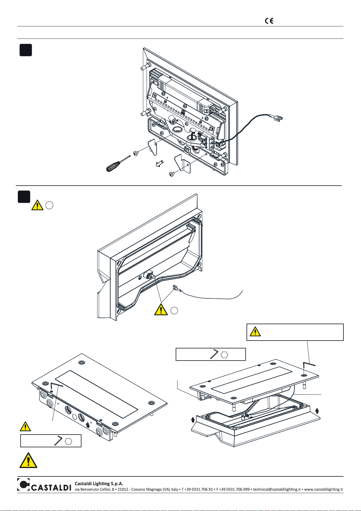
2DIE STIFTSCHRAUBEN UND GERÄTESCHRAUBEN
LOCKERN
ACHTUNG: DEN FLACHSTECKER
DES ERDUNGSKABELS ABZIEHEN
3
NETZKABEL
EIN AUSREICHEND LANGES KABELENDE EINZIEHEN,
UM DIE ELEKTRISCHEN ANSCHLÜSSE AUSFÜHREN
ZU KÖNNEN
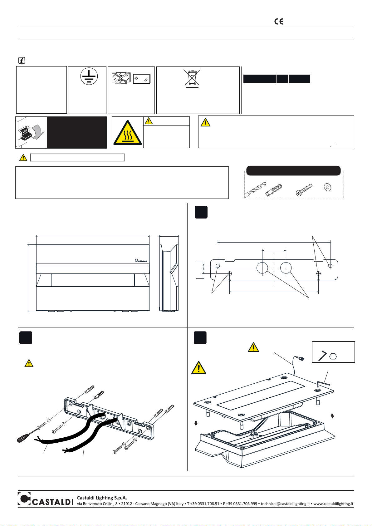
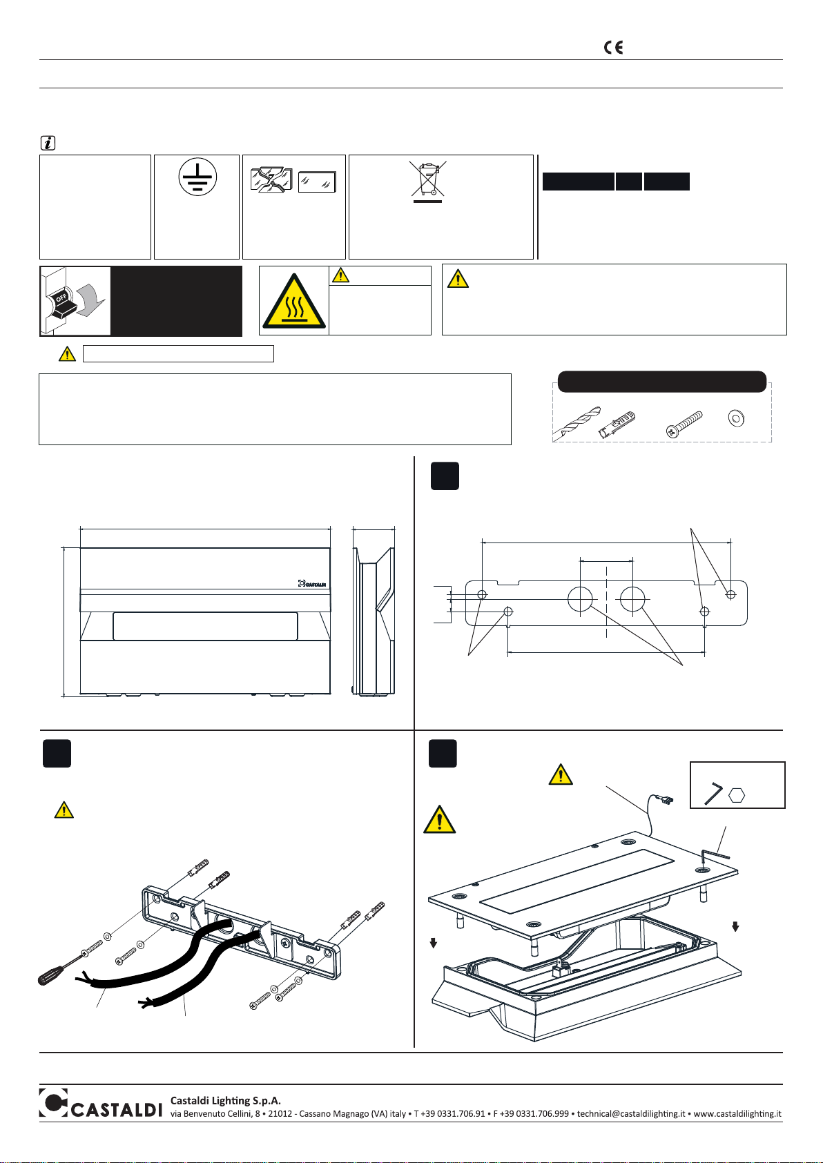
ABMESSUNGEN DES GERÄTS
ERDUNGSKABEL
DES GEHÄUSES
DALI- ODER
LOOPING-KABEL
(SOFERN VORHANDEN)
DIE 4 SCHRAUBEN LÖSEN
155
260 43
Befestigungsbohrungen
des Geräts
Befestigungsbohrungen
des Geräts
Bohrungen für
Stromkabel o Ø19
DIE GRUNDPLATTE MIT SCHRAUBEN, DÜBELN UND
UNTERLEGSCHEIBEN AN DER WAND BEFESTIGEN
40
3,50
9,50
150
190
BOHRBILD
5
BEILIEGEND
Eigenschaften - Bedeutung der Symbole auf dem Typenschild:
Hinweis: Werkzeuge, Schrauben, Unterlegscheiben und Dübel sind nicht im Lieferumfang enthalten
ACHTUNG
Trennen sie das gerät
von der netzspannung,
bevor sie arbeiten jeder
art ausführen!
ACHTUNG WARTUNG
Das Glas der Leuchte sowie alle Aussenflächen des Gerätes müssen regelmässig gereinigt werden, so dass Ablagerungen
von Erde oder Schmutz ausgeschlossen sind. Die o.a. Ablagerungen beinhalten die Gefahr einer Überhitzung und verhindern
die Vorschriftsmässige Lichtabstrahlung und Wärmedissipation.
Die Lichtquelle dieses Geräts darf nur vom Hersteller, dem Kundendienst des Herstellers oder einem sonstigen
Elektrofachbetrieb ausgewechselt werden.
LED VERSION:
Heiße Oberfläche.
NICHT anfassen.
Vor dem Berühren
abkühlen lassen.
ACHTUNG ACHTUNG:
Bei Aussenmontage ist es Pflicht, biegsames dreipoliges Kabel aus Neoprengummi
Typ H07RN-F mit Durchmesser zwischen 6 und 12 mm zu verwenden. Es sind keine
Kabel mit PVC - Isolierung oder mit externem Hülsen aus PVC, jedenfalls anderen als die
hier angeführte Kabeltype zulässig. Das Kabel ist nicht im Lieferumfang des Geräts enthalten.
x4 x4
Bei der Montage anbohren und für die Art der
verwendeten Halterung geeignete Schrauben verwenden.
x4
Ø 8mm
Klasse I
Einfache Isolierung:
erfordert eine
Schutzerdung.
IP65
Das Gerät ist vollständig
gegen Staub geschützt.
Geschützt gegen
Spritzwasser aus allen
Richtungen.
Den Schutzschirm ersetzen,
wenn er beschädigt ist.
Wenden Sie sich an unsere
Firma oder an einen
unserer Händler.
Es ist verboten, das Gerät im Hausmüll zu entsorgen.
Das Gerät muss am Ende der Lebensdauer
ordnungsgemäß entsorgtwerden.
“WEEE-Zugehörigkeitskonsortium: Ecolight”.
Nr. Nationles Herstellerregister: IT0801000000166
Versions
WP (Kg)Code
D68/F1-... 10 2,1
D68/F1-...HP 16 2,1
D68/F2-... 12 2,1

2
D68-Kea facade Mono/Bi-Emission
MI/2054 - 3aed. DEU - 07/2017 Das Produkt entspricht den Richtlinien
der Europäischen Gemeinschaft
Montageanleitung - Instandhaltung
DAS NETZKABEL DURCH DIE DICHTMEMBRAN EINZIEHEN,
MIT DER KABELSCHELLE FIXIEREN UND MIT DER
KORREKTEN POLUNG ANSCHLIESSEN
6A
6B 6C
4DAS GERÄT AN DIE
ZENTRIERELEMENTE
ANSETZEN
A.
ACHTUNG: DIE ABGEBILDETEN ARBEITSSCHRITTE EINHALTEN,
DAMIT DIE IP-SCHUTZART GEWÄHRLEISTET IST
5DIE MEMBRAN DER KABELDURCHFÜHRUNG
DURCHSTECHEN UND DAS KABEL EINZIEHEN
B.
NICHT DIE LED-PLATINEN
BERÜHREN
NETZKABEL
DALI- ODER
LOOPING-KABEL
(SOFERN VORHANDEN)
NETZKABEL
ERDUNGSKABEL
DES GEHÄUSES
ERDUNGSKABEL
DES GEHÄUSES
ERDUNGSKABEL
DES GEHÄUSES
DALI-KABEL (SOFERN VORHANDEN)
LOOPING-KABEL (SOFERN VORHANDEN)
ERDUNGSKABEL
DES GEHÄUSES
ELEKTRISCHER ANSCHLUSS DER
LOOPING-VERSION (SOFERN VORHANDEN) ELEKTRISCHER ANSCHLUSS DER DALI-VERSION
(SOFERN VORHANDEN)
BEI DEN ANSCHLÜSSEN AUF DIE KORREKTE
POLUNG ACHTEN BEI DEN ANSCHLÜSSEN AUF DIE KORREKTE
POLUNG ACHTEN
BEI DEN ANSCHLÜSSEN AUF DIE KORREKTE
POLUNG ACHTEN
*Imax = 6 A/mm²
@ typ B10
LOOPING
D68/F1-........... 40
D68/F1-......-HP 40
D68/F2-............ 40
N°max Gerät*

3
D68-Kea facade Mono/Bi-Emission
MI/2054 - 3aed. DEU - 07/2017 Das Produkt entspricht den Richtlinien
der Europäischen Gemeinschaft
Montageanleitung - Instandhaltung
7DIE ZENTRIERELEMENTE NACH
DEM KABELANSCHLUSS
WIEDER ABNEHMEN
SCHLIESSEN DES GERÄTS
VOR DEM SCHLIESSEN DES GERÄTS SICHERSTELLEN, DASS DIE DICHTUNG EINWANDFREI SAUBER IST UND KORREKT IN DER
DICHTNUT SITZT. ZUM SCHLIESSEN DES GERÄTS DIE SCHRAUBEN EINSCHRAUBEN UND DIE STIFTSCHRAUBEN BIS ZUM
ANSCHLAG FESTZIEHEN
8
GRUNDPLATTE
ERDUNGSKABEL
DIE 2 STIFTSCHRAUBEN
FESTZIEHEN
ACHTUNG:
VOR DEM SCHLIESSEN DER
LEUCHTE DEN FLACHSTECKER
DES ERDUNGSKABELS AN
DAS GEHÄUSE ANSTECKEN
*
*
ERDUNGSKABEL
DES GEHÄUSES
5
A.
DIE GRUNDPLATTE DES GERÄTS BEFESTIGEN
B.
DAS GERÄT SCHLIESSEN
3
BEILIEGEND
BEILIEGEND
DIE 4 SCHRAUBEN
EINSCHRAUBEN UND
MIT 4 Nm FESTZIEHEN
Table of contents
Languages:
Other Castaldi Lighting Outdoor Light manuals
Popular Outdoor Light manuals by other brands

Enlite
Enlite EN-WU021 manual

LIGMAN
LIGMAN LBX 7 installation manual

Luminar Outdoor
Luminar Outdoor 59269 Owner's manual & safety instructions

ASTRO
ASTRO Mast 7144 instructions

STEINEL PROFESSIONAL
STEINEL PROFESSIONAL SensorLight L 680 LED installation instructions

LIGMAN
LIGMAN TAURAS 3 installation manual