Ø189
85 165
276 183
217
286
284
353
85
165
205
217
207
2
87
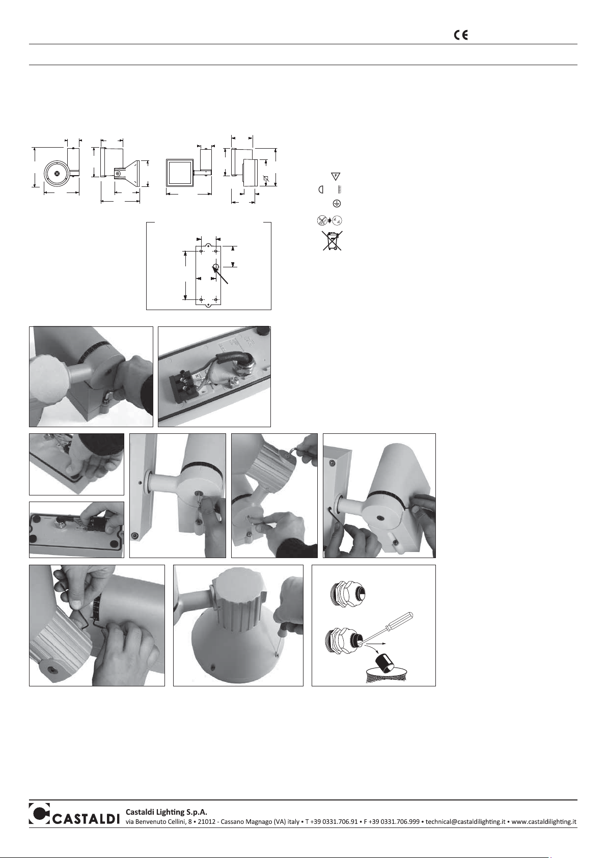
INSTALLAZIONE
• per installazioni in esterni è obbligatorio utilizzare (CEI EN 60598-1;
CEI 20-40/CENELEC HD516S1) cavo tripolare flessibile in gomma neoprene tipo
H07RN-F con diametro compreso tra 7,5 e 12 mm. Precedere come indicato in figura 8.
Non sono ammessi cavi isolati in PVC o con guaina esterna in PVC o comunque diversi
da quello qui precisato.
N.B.: il cavo idoneo è fornibile a richiesta
• per aprire l’apparecchio svitare le due viti del corpo (fig. 1)
• utilizzare la base per segnare i punti di fissaggio al muro.
• fissare la base sul muro.
ATTENZIONE: verso di assemblaggio BASE-APPARECCHIO obbligatorio
• collegare i cavi di fase-neutro al morsetto, rispettando le polarità e il cavo di terra
all’apposita piastrina (fig. 2).
• per garantire una perfetta tenuta stagna, dopo aver fissato l’apparecchio, inserire i
gommini di tenuta come indicato in figura 3.
• innestare il morsetto (fig. 4) e unire il corpo dell’apparecchio alla base a muro riavvitando
le due viti. Assicurarsi che la
guarnizione sia in buone condizioni e
che la superficie di battuta sia pulita.
• orientare il proiettore nella direzione
prescelta aiutandosi con le due scale
graduate, e serrare la vite per la
versione Q2 (fig. 5A) o le due viti per
la versione T2 (fig. 5B).
Serrare leggermente i grani per
evitare che il proiettore possa ruotare
accidentalmente (fig. 6).
RICAMBIO LAMPADA (T2-Q2/MH)
per accedere alla lampada occorre
svitare le viti nella parte posteriore
della testa dell’apparecchio (fig. 7).
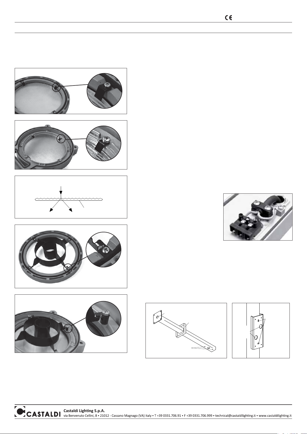
RICAMBIO DEL CIRCUITO LED -
MANUTENZIONE
Nota bene: Per l’acquisto del
circuito LED rivolgersi alla nostra
Azienda o ai nostri rivenditori.
L’intervento di sostituzione deve
essere eseguito da un impiantista
qualificato.
ACCESSORI
è possibile dotare l’apparecchio di
accessori che permettono di ottenere
fasci colorati ed altro, come riportato
nel catalogo del prodotto.
Caratteristiche apparecchio e significato dei simboli riportati in etichetta:
apparecchio idoneo per funzionamento in aria libera in ambienti interni ed esterni
montaggio a parete - soffitto - palo
IP65 apparecchio totalmente protetto contro la polvere
apparecchio protetto contro i getti d’acqua provenienti da ogni direzione
apparecchio idoneo per montaggio su superfici normalmente infiammabili
distanza minima tra apparecchio e soggetto illuminato
Classe I isolamento semplice - è richiesta la messa a terra di protezione
sostituire i vetri di protezione se danneggiati
è vietato lo smaltimento come rifiuto urbano
è obbligatoria la raccolta separata a fine vita del prodotto
“Consorzio di appartenenza RAEE: Ecolight.
Registro Nazionale dei Produttori N°: IT08010000000166”
fig. 1
fig. 2
60
50
165
70
INTERASSI DI FORATURA
BASE
fig. 4
fig. 3
• superficie esposta al vento:
D55/T2 0,06m2
D55/Q2 0,08m2
• peso: D55/T2 3,5Kg
D55/Q2 5,0Kg
• campo di installazione
(altezza): qualsiasi
MI/1782 - 3aedizione - 02/2014
istruzioni di montaggio - manutenzione D55 flex/T2-Q2-MH-LW
fig. 6B-T2
fig. 8fig. 7
Controllo qualità: In caso di reclamo mettersi in contatto con la nostra azienda o con la nostra organizzazione di vendita citando l’ordine di acquisto
e il numero di matricola che contrassegna l’apparecchio.
Manutenzione:
•
attenersi strettamente al tipo e alla potenza di lampada indicati in targa. Leggere attentamente le istruzioni fornite dal costruttore della lampada per il suo corretto uso.
Il ricambio lampada va effettuato con la massima attenzione evitando che possano sporcarsi la guarnizione di tenuta e la battuta d’appoggio relativa. È quindi necessario,
prima di procedere all’apertura dell’apparecchio, pulirlo accuratamente. Se la guarnizione di tenuta si presenta deformata e non in perfette condizioni è necessario sostituirla
.
• è essenziale effettuare una periodica pulizia del vetro e della superficie esterna dell’apparecchio su cui non debbono formarsi depositi di terra e sporcizia. Tali depositi
provocano infatti pericolosi surriscaldamenti impedendo la corretta emissione di luce e la corretta dissipazione termica. Eventuali depositi di calcare incrostati sul vetro
vanno eliminati con un raschietto.
ingresso
linea
fig. 5B-T2
fig. 6A-Q2
fig. 5A-Q2
D55/T2 D55/Q2
Ø min 8,5 mm
Ø max 12 mm
Ø min 7,5 mm
Ø max 8,5 mm
prodotto rispondente ai requisiti previsti
dalle Direttive Comunitarie Europee
P
NOTA BENE: Le presenti istruzioni di montaggio devono obbligatoriamente essere consegnate all’utente finale affinché conosca le corrette modalità di manutenzione e ricambio
lampada. È vietata qualsiasi manomissione e/o trasformazione dell’apparecchio che deve essere installato e utilizzato: così come fornito e in conformità alle Norme Impianti
Nazionali. Installazioni non conformi fanno decadere ogni forma di garanzia, l’Azienda non risponde dei danni causati da un errato montaggio.