Castelmonte HELIOS PELLET Manual

00
HELIOS PELLET
HELIOS PELLETHELIOS PELLET
HELIOS PELLET
OPERATING AND MAINTENANCE HANDBOOK

INDEX
A. GENERAL INFORMATION
a.1 Safety instructions
a.2 Technical features
a.3 Pellet
a.4 Guarantee
B. INSTALLATION INSTRUCTIONS
b.1 Initial warnings
b.2 Handling and transport
b.3 Positioning
b.4 Installation of co bustion air intake
b.5 Flue
b.6 Chi ney cap
b.7 Flue connection
b.8 Installation exa ples
b.9 Testing and co issioning
C. OPERATING INSTRUCTIONS
c.1 Initial warnings
c.2 Radio control
c.3 E ergency panel
c.4 Turning ON fro re ote control
c.5 Setting currrent ti e and day
c.6 Turning OFF fro re ote control
c.7 Operating ode
c.8 War air ventilation
c.9 A bient te perature
c.10 Sleep ode
c.11 Chrono ode
c.12 Weekly and daily progra s
c.13 Turning ON/OFF fro e ergency panel
c.14 Self-li itation flue gas te perature
D. TROUBLESHOOTING
d.1 Alar s
d.2 Soluzions
E. MAINTENANCE
e.1 Routine cleaning
e.2 Periodic aintenance
e.3 Battery replace ent in re ote control
e.4 Disposing
e.5 Wiring diagra

A.
GENERAL INFORMATION
a.1 Safety instr ctions
ATTENTION Read carefully and comply with these rules, before installing the stove:
• All local regulations, including those referring to national and European laws, ust be
respected while installing the stove.
• Verify if the wiring and plugs are able to bear the axi u absorption of the stove, which
is reported on the plate. Connect the stove to a nor -co pliant, 230v – 50Hz ains outlet.
Do not se adapters, ultiple sockets or extensions. Make sure the electrical syste is
provided with a nor -co pliant ear thing and differential switch.
●
In order to install the stove you ust respect the current laws regarding the exhausting
through the flue. It is reco ended to connect the stove to the flue by an inspection box,
which should be easy to clean. It is necessary to refer to an authorized service center for the
installation and periodical aintenance of the stove in order to check the efficiency of the
flue draught, before and after the working season of the stove.
●
While seasonally using the stove, in case of bad draught of unfavorable weather conditions
(te perature less than 0°C), verify if the flue is perfectly insulated and not obstructed, so to
avoid its freezing and the danger of a reflux.
●
In case of fire inside the flue, i ediately switch the stove off.
●
The stove consu es as uch air as it is necessary for the co bustion; it is thus advisable to
connect the stove to the outside by a suitable piping, ending at the special slot on the back
of the stove.
●
Before the installation, ake sure the pave ent is able to bear the weight of the stove.
●
If the pave ent is ade of infla able aterial, such as parquet or carpeting, position a
protection plate under the stove, (consider that, on the front of the stove, the plate should
exceed the stove by at least 25/30c ).
●
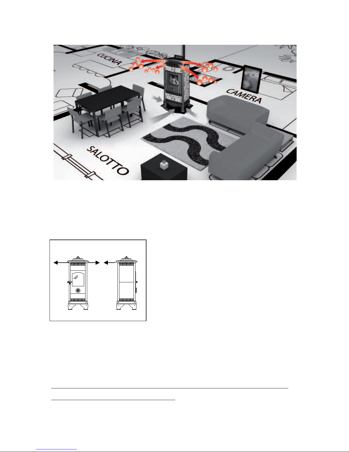
For your safety, it is advisable to aintain a distance of at least 20c between the hot sides
of the stove and possibly infla able covering aterials (such as glass-beaded walls,
wallpapers et cetera); otherwise, to use specific insulating aterials, available on sale.
Please ake this consideration also regarding the furniture, ar chairs, curtains and so on.

●
In order to facilitate the possible interventions by the technical assistance, do not fit the
stove inside closed spaces and do not place it adjacent to the walls, for this ay
co pro ise the correct afflux of the air.
●
The lack of draught by the flue (or, for instance, the obstruction or closing of the air
entrance of the grate, or of the grate itself) alters the functioning of the stove, which, while
auto atically switching-on, ay provoke an excessive pellet dosage in the grate, due to
delayed fire pri ing. Excessive s oke in the co bustion cha ber can cause an auto atic
pri ing of the fu es (gas), acco panied by a violent fla e; in these conditions, we
reco end never opening the co bustion cha ber door.
●
Co pletely avoid using infla able liquids to start the fire; when the stove is on, the pellet
lighting is auto atic.
●
The pellet feeding the stove ust necessarily present the characteristics described in this
handbook.
●
Do not touch the glass when the stove reaches its te perature; be cautious before touching
the stove.
●
Do not leave unattended children close to the stove, when it is on, because each hot surface
can cause severe burns.
●
Do not perfor interventions on the stove, apart fro those expected for a regular
functioning or suggested in this handbook in order to solve slight proble s. In any case,
always npl g the stove from the power s pply before an intervention, and operate solely
when the stove is cold.
●
It is absolutely forbidden to re ove the guard protecting the pellet tank.
●
Always ake sure and check for the co bustion cha ber door to be her etically closed
when the stove is lighting or functioning.
●
The pellet auto atic lighting is the ost delicate phase; in order for it to take place
without inconveniences, we reco end always to keep the stove and the grate clean.
• If ano alies in the functioning should occur, light the stove again only after fixing the
proble at its origin.
● Castelmonte s.r.l. is not responsible for inconveniences, tampering, breakages or any other
damage due to non-observance of the instructions reported in this handbook.

a.2 Technical Features
Maximum thermal capacity 11,5 kW
Dimensions (mm.)
x P x H
520 x 500 x 1120
Net weight 141 kg
Pellet tank capacity 17 kg
Pellet consumption (min.-max.) 0,9 – 2,3 kg/h
Run mtime ( min. – max.) 7,4 – 18,9 h
Electric power at the ignition 300 W
Electric power at the operation 100 W
Fuel Pellet ( diam. 6 mm.)
Exhaust pipe diam.80 mm.
Control and setting Radiocontrol
Automatic combustion control NO

a.3 Il pellet
The pellet f el is a prod ct with sawd st and shavings of wood processing that are dried, and
thereafter compacted at high press re, only thanks to the binding capacity of lignin, a s bstance
nat rally present in the wood , no adhesive or chemicals are added .
For this reason, the pellet is considered a nat ral and renewable f el.
The pellet has other important advantages:
• has a calorific val e greater than that of wood
• is economic: the cost in € per kW of pellets is less
than methane
• Provides clean energy and non-poll ting, beca se of
its low emissions of CO
• It is convenient to carry and easy to s pply
• It is safe beca se it is less flammable fossil f el
• leaves only small amo nts of ash after se
NB: The se of pellet of very low q ality or of different material as f el for yo r stove damages
the device and ca ses the cessation of warranty and man fact rer liability.
On the market are available different types of pellet that mainly depends on what mixt re of
woods is sed.
The table below s mmarizes the main characteristics of the pellets recommended:
Diameter 6 – 6,5 .
Maxim n lenght 20 - 25 .
Calorific Val e 4,9 kW/Kg.
H midity ax. 10%
Ash ax. 0,5%
Material 100% non treated wood
The stove is designed to b rn pellets of non-resino s wood, so se a pellet poor interventions
involve freq ent internal cleaning of the brazier, glass and comb stion chamber.
The pellet sho ld be stowed in a dry and sheltered area; attention sho ld be given to the
handling of the bags to prevent cr shing of the same res lting in the formation of sawd st.

a.4 G arantee
The guarantee is valid only if the official aintenance certificate attached to the stove is
signed by the Authorized Castel onte Service Center, which is the only one authorized to
start up the stove.
The expected 24-months g arantee is valid excl sively when the installation and test are
performed by an A thorized Castelmonte Service Center.
We would like to ake clear that the guarantee expires in case of ta pering, breakages, and
si ilar, due to non-observance of the instructions reported in this handbook.

B. INSTALLATION INSTRUCTIONS
b.1 Initial warnings
The stove ust be installed on a pave ent that presents an adequate load capacity. If the
existing building does not satisfy this require ent, appropriate easures (for instance a
burden distribution plate) ust be taken.
The installation of the device ust guarantee an easy access to clean the stove, the
exhausted gas piping and the flue.
Air e traction fans or other devices that can create a depression, installed in the
same room of the stove, can cause malfunctioning of the stove itself.
b.2 Handling and transport
Make sure that the devised used for lifting and transporting the stove support its weight,
which is reported on the identity plate on the back of the stove. The lifting of the stove is
nor ally perfor ed with an elevation trolley, by inserting the pitchforks in the proper slots
of the wooden packing. In order to position the stove inside a roo , a good general rule is to
lay the stove on the floor gently, with axi u caution and avoiding any violent i pact
b.3 Positioning
It is forbidden to install the stove in the bedroo , in the local bath or shower and in places
where there is another heating device that does not have its own adequate air inlet pipe.
(fireplace, stove, etc..). It is forbidden to position the stove in explosive environ ents.
The installation ust be in a roo which allows a safe and easy operation and si ple
aintenance. This place ust also be equipped with electrical grounding as required by law.
The stove ust be installed on a floor that presents an adequate load capacity.
We reco end putting a floor-guarding plate if the floor is fla able (i.e. parquet or
carpet.
We suggest installing the stove in a spot as central as possible to the area you wish to heat
to get the best heat circulation.

Installation m st be done by q alified personnel
For safety reasons, aintain a distance of, at least 20
c . between the hot sides of the stove and possible
fla able covering aterials (such as wood panelled
walls, wallpapers)
.
L = 20 c . in. B = 20 c . in. R = 20 c . in.
In case of presence of delicate objects, such as furniture, curtains, sofas, considerably
increase the distance of the stove.
Note: It is important to have the minim m distance of the stove from the rear wall, also to
allow a proper access to the emergency display.
L
R
B

In any case, the technician that installs the stove MUST apply all the req ested safety r les and WILL
BE RESPONSABLE of the proper installation.
Before starting the installation it is necessary to check the positioning of the stove, the chimney or
exha st eq ipment, with partic lar regard to:
- General Restrictions
- Legal distances
- Restrictions imposed by local administrative reg lations
- Limitations nder b ilding, reg lations, or contracts.
In addition, it is mandatory to check:
- The compatibility of the room with the device yo want to install
- The information given by the man fact rer regarding the technical characteristics that m st have
smoke evac ation system
- The internal section of the smoke evac ation system, the materials in which it is b ilt,
The homogeneity of the section.
- The height and the vertical development of the chimney
- The s itability of the chimney pot
- The presence of external air intakes and appropriate size of existing ones
The exha st d ct m st be s pplied and installed in accordance with the r les in force iss ed by the
competent bodies and still made in the” state of the art"
b.4 Installation of comb stion air intake
For any installation is obliged to insert an air exchange for comb stion. Close to the stove m st be
present an external air intake connection of at least 100 cm2 section
Periodically check that nothing has obstr cted the passage of air

b.5 Fl e
If yo b ild a chimney we recommend the choice of brick or ins lated stainless steel, in order to be
s re to compliance with all the necessary conditions for the proper operation of the stove.
IMPORTANT: The design and installation of a fl e m st be done by q alified technician in
compliance with the existing r les.
If, however, yo are forced to se an existing brick fl e, have it inspected by a technician to make s re
it meets the req irements below:
- It m st be perfectly watertight and airtight and s itably isolated
- It m st be made from materials resistant to normal mechanical stress, heat, the action of prod cts of
comb stion and their condensates.
- It m st not have obstr ctions along its entire length
-It m st be properly ins lated in order to avoid the formation of condensate and the cooling of the
f mes
-It m st be placed at a proper distance from flammable materials
- Its internal section sho ld preferably be circ lar. The sq are or rectang lar sections m st have
ro nded corners with a radi s not less than 20 mm.
-It m st have a constant internal section.
-The base of the chimney m st be provided with a collection chamber to facilitate maintenance and
cleaning
NO
NO
YES
ISOLANTING MATERIAL
PREFABRICATED EXTERNAL BLOCK
INTERNAL DUCT IN REFRACTORY MATERIAL
“U” S RUC URE
A ACHED O HE
WALL
FLUE RECESSED
IN HE WALL
FLUE A ACHED O HE WALL

WARNING:
-Both the chimney that the connection pipe m st receive exha st of a single stove.
- It is absol tely forbidden to discharge f mes witho t proper chimney. It is important avoid
bottlenecks that obstr ct the exit of smoke.
YES
NO
YES
NO
INDIPENDENT FLUESSHARED FLUES

b.6 Chimney Cap
It ust be located in a full wind position and the fu e outlet section ust be at least twice
the section of the flue.
If the chi ney cap is located at less than 3 eters fro higher part of the building, it ust
be raised until it is higher than the highest roof.
It is necessary verify that:
- the chi ney cap is properly operating extracting the fu es
- the chi ney cap ust be constructed in such a way as to prevent the penetration of rain,
snow or foreign bodies into the flue, as well as to assure the discharge of fu es in any wind
condition.
We suggest the use of chi ney cap having anti-wind shape and design that generate a
Venturi effect, that is, drawing out the fu es fro the flue even in presence of strong
horizontal winds.
3, oo m
3, oo m
3, oo m0, 60 m
NO
NO
YES
YES
NO

b.7 Fl e Connection
- The flue connection ust be ade with specific tubes fitted with seal junction
- Use the ini u nu ber of bends, trying to li it at two the nu ber of the sa e.
Open curves at 45 ° are advisable.
- When connecting the exhaust channel to the flue, ake sure that it is co pletely sealed
and airtight.
- If the connection tube passes through a ceiling, it ust always be insulated fro
the wall to prevent a radiant effect and a sudden reduction of the fu e te perature.
- Asse bly the exhaust channel in such a way to ensure it is airtight, using suitable
aterials that can withstand the product of co bustion and their condensates.
- The exhaust channel ust be easy to inspect and allow soot recovery and cleaning.
- Avoided as far as possible, the use of horizontal lines of tubes. In the case, use
tubes with a ini u slope of 3% upwards and axi u length less than 2
eters
- The connection pipe ust have a constant section. It is absolutely forbidden
the use of pipe sections s aller than expected fro the exit of the stove.

b.8 Installation examples
N.B. he above mentioned information is merely indicative for a proper installation.
Castelmonte s.r.l. is not responsible regarding the installation.
NO
CHIMNEY CAP CHIMNEY CAP
INSULATED
PIPE
NOT INSULATED
PIPE
EXTERNAL AIR
INTAKE
EXTERNAL AIR
INTAKE
INSPECTION “T”
CONNNECTION INSPECTION “T”
CONNNECTION
INSULATED
FLUE
INSPECTION
“T”
CONNNECTION
BRICK
CHIMNEY
INSPECTION “T”
CONNECTION
sloping 3-4%
Min. 1,5/2
Max. 2
The ash is
accu ulatine into
the 90° bend
CHIMNEY CAP
It is strongly reco ended not to install a
90 ° bend (see below) as the first piece
because the ash would block the passage of
s oke and cause proble s to the draught of
the stove

b.9 Testing and commissioning
Before starting up the stove is necessary to test the installation to verify proper operation of
all parts including:
- Connection to the s oke evacuation syste -
- The electrical connections
- Presence and efficiency of the air intake
The test is considered positive only after that all phases of the operation will be completed
witho t any fa lts happen.
The commissioning of the nit m st be carried o t by an a thorized technician or the
warranty expires.

C. OPERATING INSTRUCTIONS
c.1 Initial warnings
- Do not use the equip ent as an incinerator or in any other way other than
for which it was designed
- Do not use other fuel outside of the pellet quality confor to the specifications
previously reported
- Do not use liquid fuels
- The unit, when in operation, reaches high te peratures to the touch (especially the
external surface), handle with care to avoid burns
- Do not ake any unauthorized odification to the equip ent
- Use only original spare parts reco ended by the anufacturer
- Keep always the stove clean to ensure good efficiency and a correct operation.
At the first start there might be a slight amo nt of smoke and odo r ca sed by comb stion of
resid al protective. This will stop after abo t an ho r of operation. Therefore, it is advisable to
ens re the effective ventilation to the room d ring the first ignition
D ring the increase or decrease of the thermal power yo may hear the creaking d e to
normal thermal expansion of the metals that make p the stove.
The commissioning of the nit m st be carried o t by an a thorized technician or the
warranty expires.

c.2 Radio control
The stove is controlled through the re ote control or in case of e ergency by the s all rear
“e ergency panel”.
The re ote control is used to adjust all of the operating para eters, set the ti er, but
especially to continuously onitor the a bient te perature. The keyboard of the re ote
control is equipped with rubber keys, the upper directly accessible, while the lower keys are
hidden by the door.
Re ote radio control with open door
Pressing the keys the display lights and the lighting stops after 10 seconds.
To operate the re ote control 2 batteries 1.5 V (AAA) are required.
It is advisable to keep spare batteries at ho e.
The remote control performs the f nction of room thermostat and therefore it is
recommended to keep it in the room where the stove is installed
Keep the remote control away from so rces of direct heat and water. It is advisable to keep it
o t of reach of children
Note: Do not press the Key (key 14) on the remote control (see legend on next page) beca se
its se will be managed excl sively by the a thorized service centers.

Key legend:
1. Mode Key
2. Fan key
3. Plus circular key
4. Roo key
5. Minus circular key
6. Sleep key
7. Ecostop key
8. Crono
9. Plus triangular key
10. OK key
11. On /Off key
12. Minus triangular key
13. Clock key
14. Key button
remote control keyboard
Display is divided in 5 areas:
Area 1: days of the week
Area 2: icon that indicates the
data trans ission
Area 3: clocks. This area is split
in 2 parts: clock ON (that
indicates the current ti e.) and
clock OFF (that indicates the
ti e of shut down in Sleep
ode.) Between the 2 areas
there is a clock icon that
indicates the Chrono ode.
Area 4: the icon allow you to
understand the fan speed
Area 5: The icons show the
operating ode of the stove.
Re ote Control
Display Radioco ando

c.3 Emergency Panel
At the rear of the stove there is an e ergency panel, which allows diagnosing any
ano alies as well as to per it the operation in the case in which the re ote control is not
functioning
1: Alarm reset b tton. Also functions as diagnostic of the state of operation of the stove.
Except for resetting the alar s, the button and the consequent activation, should be used
only by authorized service centers. In case of accidental pressures, the panel exits the view
state within 24 seconds
2: Self-learning remote control. It allows the receiver of the e ergency panel of self-learning
code trans itter that sends infor ation to the stove
3: Three position selector to choose 3 power levels also without re ote control.
4: Three position selector to operate with or without re ote control.
5: 3 Digit Display It indicates infor ation about the stove operation and the alar s.
6: green LED. Operation condition of the stove.
7: red LED. Operation condition of the stove.
CASTELMONTE
5
6
4
3
1
7
2
E ergency Panel
Table of contents
Popular Stove manuals by other brands

GAS ONE
GAS ONE B-5100 Owner's Manual and Operating Instructions

THERMOROSSI
THERMOROSSI ecotherm 3001 Installation, use and maintenance guide

ECOFOREST
ECOFOREST MIAMI Installation and maintenance manual

Saey
Saey 94 MF Installation and user manual

Wagener
Wagener Fairburn Installation, operation & maintenance instructions

Kenyon Marine
Kenyon Marine 500 Instructions and parts list

Ancona
Ancona AN-2340 installation instructions

Bronpi
Bronpi Kenia series instruction manual

Lopi
Lopi 440-T owner's manual

Ozark Trail
Ozark Trail Two Burner owner's manual

Broseley
Broseley York Midi SE Installation & operating instructions

Country Hearth
Country Hearth 3000 L Owner's operation and instruction manual