Saey PEAK GAS S.C. User manual

SAEY PEAK GAS S.C.
EN - Installation and user manual

2

3

4
CONTENTS
1 INTRODUCTION ......................................................................................................................5
2 PACKAGING...........................................................................................................................6
3 TECHNICAL DATA ....................................................................................................................6
4 GENERAL INFORMATION AND SAFETY INSTRUCTIONS ......................................................................8
5 INSTALLATION INSTRUCTIONS ....................................................................................................9
6 INSTRUCTIONS FOR USE..........................................................................................................17
7 MAINTENANCE ....................................................................................................................20
8 TROUBLESHOOTING ..............................................................................................................21
9 SPARE PARTS .......................................................................................................................21
10 WARRANTY .........................................................................................................................22
11 SERIAL NUMBER ...................................................................................................................22

5
1 INTRODUCTION
Congratulations! Thank you for choosing a SAEY stove.
With SAEY, service does not end with your purchase! Our certified dealers and Fero Service guarantee
the flawless operation of your stove, and therefore many years of heating pleasure.
By registering your stove, you can also count on faultless after-sales service and warranty processing,
and we can keep you informed of any news about your appliance.
We are therefore convinced that you will have many enjoyable days ahead and wish you every success!
Declaration of conformity
As the manufacturer, we declare that the appliance has been manufactured in compliance with the
essential requirements of the specific EC directive 2009/142/EC on gas appliances.
Important
Please, before putting your gas fireplace into operation, carefully read these installation
instructions. This will avoid mistakes when using the device and a consequent need to contact the
professional service.

6
2 PACKAGING
We take great care to deliver your new stove in the best possible packaging in order to reduce the risk
of damage. Therefore, please be sure to check your stove for damage and completeness on receipt.
Report any missing parts to your installer immediately.
The packaging material used is environmentally friendly and therefore only recyclable packaging materials
are used. If you dispose of the packaging yourself, do so according to the regulations or at a recycling
centre.
3 TECHNICAL DATA
PEAK SAEY GAS S.C.
Type of gas
Natural gas
Liquefied gas
G20
G25
G30
Rated power input (kW)
9,5
Rated nominal power (kW)
8,1
8,4
8,2
Combustion efficiency (%) according
to EN
85
88
86
CO2 content(%)
6,6
9,9
7,7
NOx content in flue gases (mg/kWh)
49
61
70
Flue gas temperatures (°C)
250
225
Connection flue exhaust (mm)
Ø 100
Required chimney draft (Pa)
5
Weight
84 Kg
Safety thermostat –chimney fuse
Type HOS 120
Connecting dimensions
G½“

7
Overview of pressure settings
PEAK SAEY GAS S.C.
Natural gas (G20)
with overpressure
20 mbar
Natural gas (G25)
with overpressure
25 mbar
Liquefied gasses
(G30) with
overpressure
30 mbar
(calorific value Hi=34,9
MJ/m3, Index
Ws=50,72 MJ/m3)
(calorific value
Hi=34,02 MJ/m3,
Index Ws=50,72
MJ/m3)
(calorific value
Hi=115,98 MJ/m3,
Index Ws=78,84
MJ/m3)
Nozzle
overpressure for
maximum (mbar)
13,8
18,8
27
Nozzle
overpressure voor
minimum (mbar)
3,5
8,5
13,5
Gas flow/hour at
nominal power
0,986 m3/u
1,116 m3/u
0,735 kg/u
All data for the calorific value Hi, Wobbe index Ws and flow rates refer to the temperature of 15 °C and a pressure
of 1013 mbar of dry gas.
NOx - concentration in flue gas –limit values (according to EN 613 A1)
These correspond to NOx, klasse 5.
Dimensions
Class
N0x mg/kWh
1
2
3
4
5
350
260
200
150
100

8
4 GENERAL INFORMATION AND SAFETY INSTRUCTIONS
The following general safety instructions must be strictly observed:
- During combustion, heat is released which causes the top of the stove, the doors, the door handles,
the window, the smoke pipes and possibly also the stove mantle to heat up considerably.
- Inform your children of this danger and keep them at a safe distance when using the stove.
- It is forbidden to place non-heat-resistant objects in the vicinity of the stove.
- It is forbidden to place a water kettle on top of the stove.
- When using the stove, do not use easily inflammable or explosive materials in the same or adjacent
rooms.
- No changes may be made to the device.
- Use only the manufacturer's original spare parts.
- This stove is not suitable for installation on a chimney to which several stoves are connected.

9
5 INSTALLATION INSTRUCTIONS
All local directives, including those relating to national and European standards, must be
observed when installing the stove.
Only an appliance connected by an installer guarantees the observance of the directives on building
construction and fire prevention. This is absolutely necessary for the correct and safe operation of the
stove.
The service life of your stove depends on correct installation, proper operation and regular maintenance.
Distances to be observed around the stove
Flammable materials and objects in the vicinity of the stove must be kept at a minimum distance of 500
mm from the appliance. The minimum distance for combustible objects located above the stove is 250
mm.
If the floor under the stove is made of a combustible material, it is necessary to fit a protective plate on
which the stove can be placed.
The thermostat sensor is used to detect the room temperature and is located on the rear wall of the
stove. We recommend that you check this location. If it is covered or shielded, the ambient temperature
on the thermostat may be read incorrectly and the control may not be carried out correctly.
Make sure that the temperature on the surface of combustibles behind the protective shield does not
exceed 80°C. To reduce the distance from flammable materials, have a protective shield fitted by an
installer.

10
5.1 Placement of appliance
The stove may only be installed on a floor with a sufficient load-bearing capacity. If the floor is not
suitable, measures must be taken to increase the load-bearing capacity. In order to be able to place the
appliance flatly, it is provided with adjustable feet (adjustment screws).
(adjustment screws). If necessary, adjust these so that the appliance is installed as flat as possible.
A gas revision must be carried out for the gas supply to the stove.
Before installation, it is necessary to check whether the type and pressure of the gas in the distribution
network corresponds to the gas opening setting according to the technical data.
The stove may only be operated in a well-ventilated room with sufficient combustion air. Install an air
vent of at least 15cm² that cannot be closed.
If, in the same room and at the same time as the stove, a mechanical ventilation system is in use
(ventilation, tumble dryer, etc.), it must be ensured that sufficient air is supplied and that there is no
underpressure of more than 4 Pa.
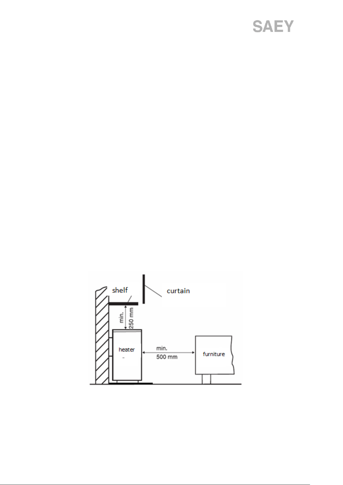
The installation of the stove is prohibited in rooms where there is a risk of explosion or flammable
conditions (such as garages).
The thermostat used to detect the temperature in the room is located on the rear wall of the heater.
Poor air circulation in the room or an atmosphere that is too cold may affect the operation of the
thermostat.
The installation must comply with the standards:
- For gas distribution systems EN 1775 - ED. 2, 38 6462 and TPG 704 01
- For installation according to 73 4201 - ED. 2, 06 1008
- Fire classification of construction products and structures EN 13501-1 + A1
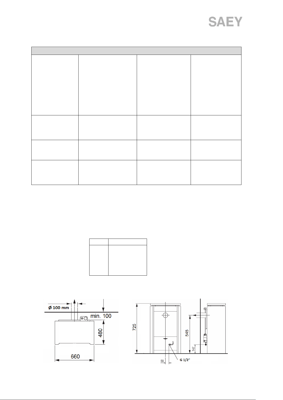
Gas connection
- A gas connection must be installed in the same room as the appliance.
- The maximum distance between the connection and the stove is 1.5 m
- Flexible gas pipes may be used if they have been approved for this purpose
- The gas pipe must not be used as a supporting structure.
Recommendations for connection
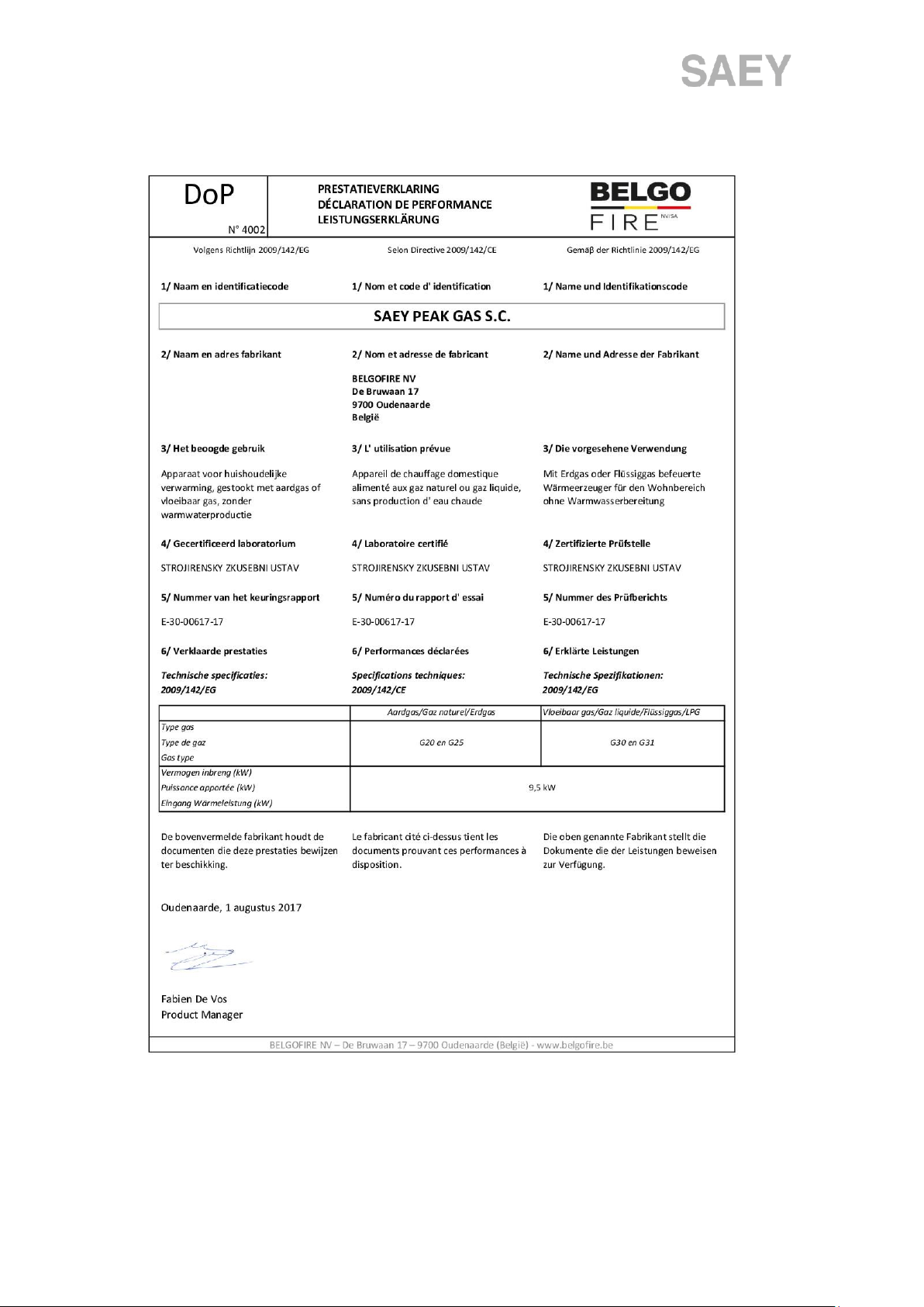
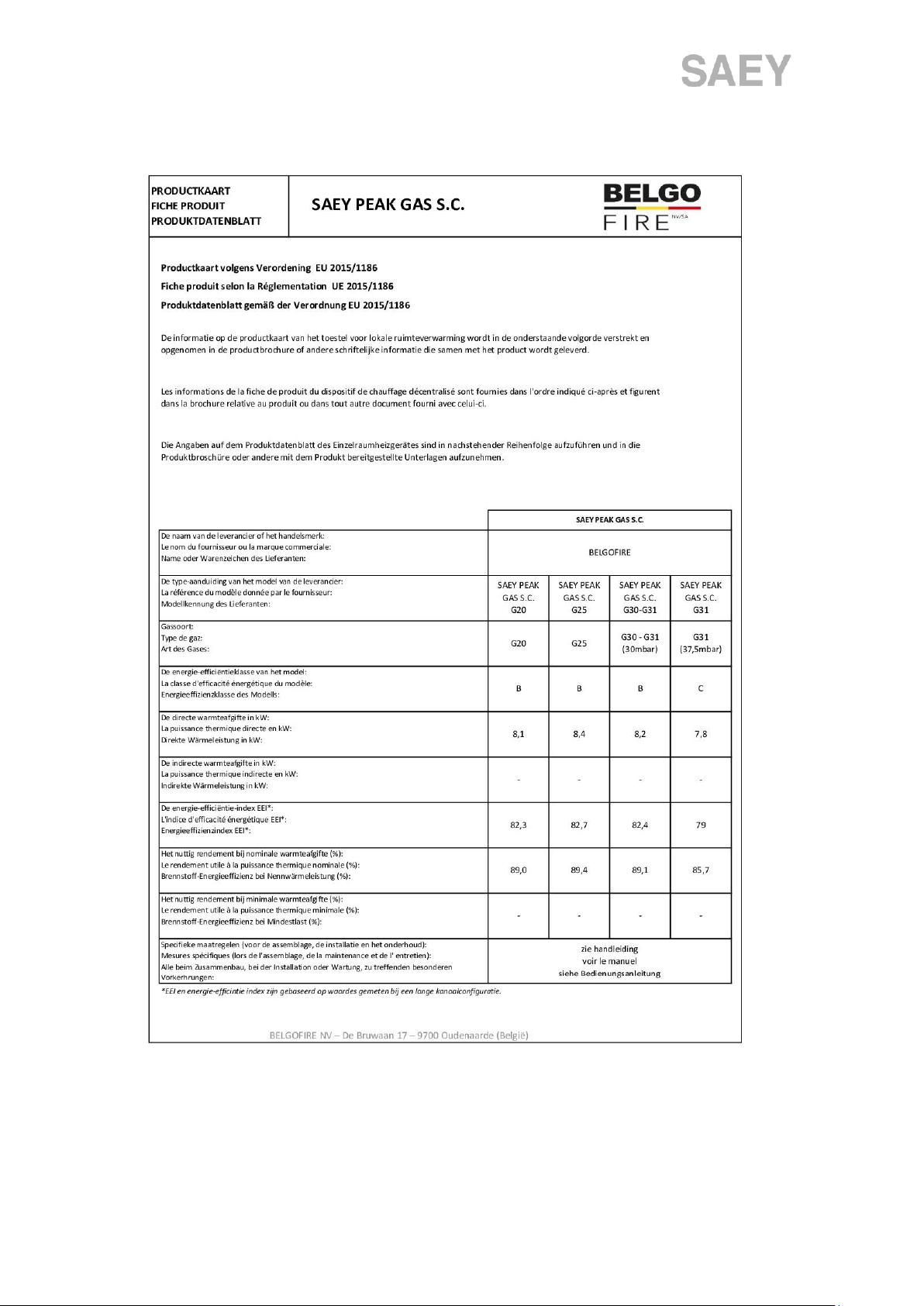
The stove may only be used for the specified gases:
-Natural gas G20 and G25
-Liquid gas G30 and G31
Other types of gas are prohibited fort he sppecified stove

11
Connecting the chimney
The stove must be connected to a chimney in accordance with the applicable standards and on the basis
of the inspection report issued. The installation must be carried out only by an authorised expert in
chimneys.
The stove can only be started up after an inspection of the chimney and after the stove has been properly
connected by the relevant specialist.
During the first start-up, it is advisable not to use any other appliance (hoods, fans, other stove) in order
to check the stove correctly.
Top connection and rear connection
The design of the stove offers two ways of connecting the stove pipe:
- rear connection (supplied ex-factory as standard, see figure 11);
- top connection (must be installed in accordance with the following instructions).
Conversion to top connection
The components required to convert the stove to a top connection are supplied
with the appliance: cast iron adapter ring (1pc), seal (1pc), enamelled cap (1pc), 4
self-tapping screws (see fig. 10)
Replacing the stove's flue pipe
1. Remove the top cast iron plate from the stove. On the inside, remove the metal
piece securing the round cover plate (see Fig. 12).
2. Remove the control extension rod from the gas valve (Fig. 11).
3. Remove the back plate of the metal plate to gain access to the connecting flange
and remove the flange. Make sure the original seal is installed here, which should
be used for the new assembly.
4. Carefully remove the metal round plate and the seal at the top, this will be used to seal the original
rear exhaust. Check again that the seal is correctly installed.
The tightness of this round plate is vital for the safe operation of the stove.
5. Screw on the removed connection flange and seal it to the top (see Fig. 13). The round plate covering
the original rear outlet can also be seen here.
6. Screw the enamelled sheet metal cover supplied onto the rear flap and replace the entire rear flap
on the stove.
7. Install the cast iron cover. Use the cast iron adapter ring supplied by the manufacturer to maintain
the space between the cover and the newly installed stove socket (see figure 14).
8. Reinstall the gas valve control extension rod and check for proper operation.

12
5.2 Installing ceramic logs
To avoid damage to the ceramic decoration, place the decoration after the installation of the stove, so
that you do not have to move the stove.
The first step in the installation of the decoration is to free the door, a description of which is given in
Article 6. The stove comes with a package containing the various pieces of decoration:
- 6 ceramic logs
- 1 package with vermiculite chips
- 4 ceramic charcoals (only for the G30 connection)
For natural gas (G20/G25)
Step 1
Spread the vermiculite flakes from the packaging on the bottom of the grill and form an evenly distributed
layer over the entire surface of the burner bed.
Step 2
Use the imitation wood blocks and place them appropriately in the burner chamber so that they fit
nicely. Attention! The ignitions may not be overlapped by the imitation panel. Also make sure that the
different fuels do not touch the thermocouple.
The installation of the decoration is different fort he type of gas, follow the correct
instructions.
This procedure is only necessary if the stove is connected to G20/G25!
Follow the instructions correctly to avoid damage to the stove

13
Step 3
Place the two rear imitation firewood logs in the fire chamber so that they lie completely in the corners
on the granulate - see illustration. The logs may not be placed outside the granulate. The distance to the
burner is approximately 20 mm. Slide the block of the right imitation panel into the opening of the front
one - see arrow - and adjust the position of the front block accordingly.
Step 4
Add the middle piece shown so that its overlaps the rear imitation blocks.
Step 5
Next, place the side panels on the side of the burner chamber. Make sure they are also on top of the
rear blocks.
For liquid gas (G30/G31)

14
Step 1
Place the imitation coals on the steel plate exactly as shown below. Make sure that the correct distances
and dimensions are respected and also make sure that the coals fit properly with the burner plate. Place
the 3rd piece of imitation carbon on the slanted side so that it also matches the placement of the log in
step 4.
Step 2
Now fill the grid with the granulate, in such a way that it is evenly distrubeted over the full plate. Make
sure the position of the imitation carbon does not change.
Step 3
This procedure is only necessary if the stove is connected to G30!
Follow the instructions correctly to avoid damage to the stove

15
Place the imitation wood front shown on the burner plate, tightly against the edge. Attention ! The
ignition(s) must remain free and may not be overlapped. Also make sure that no granules get between
the flames of the burner and the thermocouple.
Step 4
Place both rear imitation blocks one by one in the burner chamber, so that they rest nicely on the
imitation charcoal - see arrows. Place the right-hand block in the opening of the front block - see arrow
- and adjust the position of the front block accordingly.
Step 5
Add the middle piece shown so that it overlaps the rear imitation blocks.

16
Step 6
Place the lateral logs on the side of the burner chamber and also on both rear imitation logs.
Step 7
Chose the burner chamber
-Clean the inside of the sight glass and make sure that the ignitions are not covered with granules.
-Close the burner chamber and seal it with the countersunk self-tapping bolt.
5.3 Gas settings
The preset factory settings for the type of gas can always be read from the rating plate. Before putting
into operation, check whether the data on the rating plate corresponds to the local gas distribution (gas
type, pressure, ...). If this is not the case, the appliance must be adjusted accordingly. See the technical
data for this. The gas pressure should be adjusted or checked by adjusting the pressure on the nozzles
according to the parameters in this manual.

17
6 INSTRUCTIONS FOR USE
Location of controls
A –control knob 1 and piezo ignition knob 2
B –the universal fitting of figure 4 or the BY-PASS sliding controller
C –placement of the thermostatic
6.1 Putting into operation
- Open the gas supply valve;
- Turn knob 1 to the ignition position * and push it in as far as it will go
- Press the piezoelectric ignition button 2. Do this repeatedly until the flame is lit and then keep knob 1
pressed for about 10 seconds.
- Release knob 1. When the flame has extinguished, repeat the above procedure, but wait 1 to 2 minutes
so that the gas in the fireplace can be sufficiently ventilated.
As soon as the ignition has succeeded sufficiently, set the desired room temperature with knob 1, e.g.
at position 4. Now, the main burner can be switched on if the room temperature measured by the
thermostat is lower than requested. Otherwise, the main burner will not start because the room
temperature is the same as the one set using the control knob. The numbers on the knob do not
correspond to a preset temperature, they are purely indicative. Therefore, it is important to keep an
eye on the room temperature and adjust the control knob so that the desired temperature is reached.
At night, you can move the control knob to e.g. position 1 to obtain a lower
temperature. If you wish to turn off the main burner and burn only the
ignition burner, turn the control knob to the * symbol.
See the "troubleshooting" section in case of problems with the ignition.

18
6.2 Switching off the heating
For a short period: turn knob 1 all the way to the right
For a longer period (vacation,…): turn knob 1 all the way to the right and close the gas supply
6.3 Setting the temperature
Control via thermostat
Set knob 3 of fitting B, to the default position as illustrated. The built-in
thermostat in the gas valve will automatically control the room temperature
as set by knob 1.
The numbers shown indicate the range of the thermostat (1 is the lowest setting, 7 is the highest). It is
only after some time and with regular use that you will discover the correct setting that corresponds to
the temperature you desire. This of course depends on the location, the size of the room, the type of
house and the degree of insulation. Position 3-4 of the control knob should correspond to a 20-22°C.
The size and power of the burner flame will automatically adjust to the requested temperature. As soon
as the room temperature drops below the set limit, the thermostat will switch on, the gas supply will be
opened and the burner will ignite. When the temperature is reset, the burner will only burn at the
minimum and then increase again according to the room temperature.
It is possible that the burner will only burn at minimum on position 3 if the requested room temperature
has just been reached. It may also be that the burner in position 1 will burn at full power when the room
temperature is less than 10°C. In this way, the noise from the ignition is reduced to a minimum. When
the control knob is set to the ignition position, only the main burner will burn and the automatic function
will be switched off. A minimum temperature is then emitted into the room.
If the main burner does not start immediately after a prolonged period of inactivity, be sure
to observe the 60 second interval. Faults which you cannot solve (see chapter "troubleshooting")
must be solved by a technician. To do this, switch off the appliance, close the gas supply and wait for
a technician to arrive on site.

19
Manual control
Thermostatic operation is deactivated when the slider 3 is no longer in its standard position. With this
slider we can regulate the power and the size of the flame. By moving the slider from the zero position,
we can thus manually increase the burner output. Attention! As the thermostat is switched off, you can
no longer regulate the temperature with knob 1.
To reactivate the thermostatic function, turn knob 3 back to its standard position, as shown in the figure.
Energy-saving burning
- To save energy, reduce the temperature with button 1 during the night.
- If you open the windows for a longer period of time, reduce the temperature with the control
knob, e.g. to position 1.
Checking the exhaust gas
Operation
This gas fire is equipped with a chimney sensor to check the correct passage of the exhaust gases. This
ensures that gases do not spread into the room where the burner is installed. If, for any reason, the exit
of the gases to the outside is not possible, the temperature measured by the chimney sensor will
increase, so that after a few seconds the gas supply will be cut off and the appliance will switch off.
Putting the fire back into operation
If the above has happened and the fireplace sensor has intervened, wait a few minutes for the
temperature sensor to cool down before restarting the appliance. The smoke (gas) outlet and the
chimney must be free and must not be obstructed in any way. Carry out a visual check to this end. Only
when everything is ok again, you can restart the appliance as described above.
If the problem persists, call a technician !

20
7 MAINTENANCE
Regular inspection of the gas fire by a technician will ensure that your appliance is working properly. We
therefore recommend that you check the operation of the appliance and all parts that come into contact
with gas regularly to ensure that they are still secure. Check the flue gas outlet at least once a year. Only
original parts may be used for maintenance and repair. Any unprofessional handling or intervention on
the appliance will result in loss of warranty.
If the glass is damaged or cracked, the appliance must not be put into operation. Unprofessional repairs
by yourself, e.g. with glue, are prohibited. If the glass is damaged, it must be replaced with a new one
and the combustion chamber must be checked.
Cleaning the glass
As the stove takes in air from the room where it is situated for combustion, small dust particles can
settle on the glass. You can see this phenomenon clearly when the stove is switched off at night, allowed
to cool down and then started up again the next day. This causes condensation and therefore the
formation of a white sheen on the glass, which must be removed at least once a year. Use products
suitable for stainless steel or glass-ceramic mantles.
Disconnecting the window
! This may only be carried out by a service technician!
- Unscrew the small screw (5 mm) on the side of the door to release the handle.
- Lift the handle to release the latch and you can now open the door.
- Clean the glass and check that the seal is properly attached to the sides of
the door.
- Clean the glass with standard household cleaners. Do not use abrasive materials
as they may cause irreparable damage!
- Repeat the first step in reverse order to reattach the handle
All operations and applications mentioned in this document may only be performed by a
certified technician with the appropriate skills and documents.
Make sure that all the screws are tightened properly. This must be done by a certified
service technician !
Table of contents
Other Saey Stove manuals
Popular Stove manuals by other brands

Dimplex
Dimplex TDS8515 Parts and service manual

Dean
Dean Forge Hembury 6 operating instructions

Brixton
Brixton KO-6383DU instruction manual

Regency
Regency FIREGENIE FG37-LPG Owners & installation manual

Hunter
Hunter Compact 5 Installation and operating instructions

NORDIC FIRE
NORDIC FIRE ILVAR 7 Instructions for use

Mendip Stoves
Mendip Stoves SOMERTON 2 COMPACT Operation and instruction manual

HASE
HASE Asmara Instructions for use

Coalbrookdale
Coalbrookdale GS1i Installation and servicing instructions

NARVI
NARVI NOVA ELECTRON Series Installation and instruction manual

Centek
Centek CT-1524 instruction manual

Russell Hobbs
Russell Hobbs RHEFSTV2003B user guide