CAT Pumps 7537 User manual

DATA SHEET
PRESSURE SENSITIVE REGULATING UNLOADER
FEATURES
• Maintains full system pressure while running in bypass without full
load on pump.
• Senses pressure built up from downstream flow changes and bypasses
flow to protect pump from overpressure.
• Minimum pressure fluctuations with alternating use of multiple guns.
• Multiple ports for convenient mounting.
• Color coded spring allows for easy identification and simple change
from one model to another.
• Standard unloaders are fitted with NBR O-rings. Optional O-rings are
available for higher-temperature and chemical compatibility.
• FPM – .0110 (7537. 0110)
• FPM – .0110 (7542.0110)
Brass Models: 7537, 7542
SPECIFICATIONS U.S. Metric
7537
Flow Range 1–21 gpm 3.8–80 lpm
Pressure Range 230–2600 psi 15.8–180 bar
7542
Flow Range 1–21 gpm 3.8–80 lpm
Pressure Range 800–4000 psi 55–275 bar
Model 7537 Shown
COMMON SPECIFICATIONS U.S. Metric
Maximum Operating Temperatures:
Standard NBR O-Rings 140° F 60° C
Stnd. NBR O-Rings (Intermittent) 195° F 90° C
Optional FPM O-Rings 240° F 116° C
Inlet Ports (2) ½" NPT(F) ½" NPT(F)
Discharge Port ½" NPT(F) ½" NPT(F)
Bypass Port ½" NPT(F) ½" NPT(F)
Weight 2.54 lbs 1.15 kg
Dimensions 7.57 x 3.96 x 1.74" 192.2 x 100.5 x 44.3 mm
Use only at above specifications to ensure proper unloader life and performance.
This Pressure-Sensitive Regulating Unloader can be converted
to a Secondary Relief Valve. See page 4 for Relief Valve conversion.

SELECTION
These pressure-sensitive regulating unloaders are designed for systems with
single or multiple pumps, solenoid (gate) valves, nozzles, standard or "weep"
guns.
Note: For multiple-pump systems, it is best to use a pressure regulator, not a
pressure-sensitive regulating unloader.
These pressure-sensitive regulating unloaders should meet both the desired
system flow (combined nozzle flow rate requirement) and the desired
system pressure.
Note: Operation below the minimum flow of the unloader causes the
unloader to cycle. Operation above the maximum flows of the
unloader causes premature unloader wear, cycling and prevents
attaining desired system pressure.
INSTALLATION
These unloaders operate properly when mounted in any direction, however,
it is preferred to keep the plumbing to a minimum and the hex adjusting
nut easily accessible. The best mounting location is directly on the pump
discharge manifold head.
There are two (2) inlet connections on these unloaders. Both are ½"
NPT(F) ports and are located on the short extension side and bottom.
An arrow and the word IN is cast into the body indicating the direction
of flow. Liquid from the manifold discharge goes through these
connections.
The discharge connection is a ½" NPT(F) hex fitting. An arrow and the
word OUT is cast into the body indicating the direction of flow. Discharge
plumbing for the spray guns, solenoid (gate) valves or nozzles are connected
to this port.
The bypass connection is a ½" NPT(F) port located on the side of the body.
The word BY-PASS is cast into the body. Bypass liquid is directed out of this
port and can be routed to a reservoir (preferred method), a drain or to the
pump inlet.
OPERATION
These pressure-sensitive regulating unloaders hold established system
pressure in the discharge line when the trigger gun is closed or solenoid
(gate) valve is closed or the nozzle is clogged, thus bypassing all unrequired
flow. Squeezing the trigger gun or opening the solenoid (gate) valve will
close the bypass and return to established system pressure.
PRESSURE ADJUSTMENT
1. Setting and adjusting the unloader pressure must be done with the
system “on.”
2. Start the system with unloader backed off to the lowest pressure setting
(counterclockwise direction).
3. Squeeze the trigger and read the pressure on the gauge at the pump.
Note: Do not read the pressure at the gun or nozzle.
4. If more pressure is desired, release the trigger, turn hex adjusting nut one
quarter turn in clockwise direction.
5. Squeeze the trigger and read the pressure.
6. Repeat this process until desired system pressure is attained.
7. Once the desired system pressure is reached, stop turning the hex
adjusting nut.
Note: Pressure is not set at the factory.
Notice: A minimum by pass flow of 5% of the unloader rated flow capacity
is required for proper unloader performance. If the entire flow is
directed through the nozzle (zero bypass) the “cushioning” feature
of the bypass liquid is eliminated and the unloader can prematurely
wear or malfunction.
8. If desired system pressure cannot be reached, review
TROUBLESHOOTING chart.
9. When servicing existing systems, follow adjustment procedures as stated
above.
Note: A secondary pressure safety relief device (i.e. pop-off valve, safety
valve) should be used along with this pressure-sensitive regulating
unloader. Final adjustment for the relief valve should relieve at
200 psi above the system operating pressure.
Note: By removing the check valve and spring, these unloaders can
function as a secondary relief valve.
Read all CAUTIONS and WARNINGS before commencing service or operation of any high-pressure system
TYPICAL UNLOADER INSTALLATION
1. Pressure Gauge
2. Relief Valve
Shown as a secondary Relief Valve
3. Pulsation Dampener
4. Pressure Sensitive Regulating Unloader
5. Triplex Plunger Pump
2
DISCHARGE
OPTIONAL
INLET
INLET
BYPASS
1
5
4
3
See page 4 for Relief Valve conversion.

SERVICING
Disassembly
1. Disconnect bypass, discharge and inlet plumbing from unloader.
2. Remove unloader from pump.
3. Secure body of unloader in a vise with hex adjusting nutsfacing up.
4. Remove discharge fitting and O-ring, spring and check valve with O-ring.
5. Examine check valve and discharge fitting for wear, spring for wear or
fatigue,and O-rings for cuts or wear. Replace as needed.
Note: While the discharge fitting is removed, inspect sealing area where
the check valve makes contact within the internal body of the unloader for
grooves, pitting and wear. If damage is found, stop the repair and replace
with complete new unloader. If not, proceed with disassembly.
6. Remove two (2) hex adjusting nuts by turning in a counterclockwise
direction.
7. Remove spring retainer and spring.
8. Examine spring and spring retainer for scale build up, fatigue or wear and
replace as needed.
9. Use wrench to unthread and remove piston retainer and piston stem
together from main unloader body.
10. Examine piston stem and piston retainer for scale build up, scoring,
pitting and wear and replace as needed. Examine O-rings and backup
rings for cuts or wear. Replace as needed.
11. Remove unloader body from vise and reposition in vise with bottom
inlet port facing up.
12. Remove inlet fitting with O-ring, seat spring and ball.
13. Remove unloader body from vise and reposition in vise with bottom
inlet port facing down.
14. Drive out seat and O-ring from the top side.
15. Examine seat, seat spring and ball for scale build up, scoring and wear
and replace as needed. Examine O-rings for cuts or wear. Replace
as needed.
Reassembly
1. Remove unloader body from vise and reposition in vise with bottom inlet
port facing up.
2. Lubricate and install O-ring onto outside diameter of seat.
3. Place seat with O-ring into unloader body with small inside diameter hole
facing up.
4. Place ball onto seat and then spring.
5. Lubricate and install O-ring onto inlet fitting. Thread in inlet fitting by
hand and tighten.
6. Remove unloader body from vise and reposition in vise with bottom inlet
fitting facing down.
7. Lubricate and install O-ring and then backup ring over threaded end of
piston stem small diameter groove.
8. Install backup ring, O-ring and then backup ring on opposite end of
threaded piston stem. Lubricate all parts.
9. Lubricate and install O-ring onto piston retainer.
10. Place threaded end of piston retainer over the threaded end of the
piston stem.
11. Place piston retainer and piston stem assembly into unloader body
with threaded end of piston stem facing up. Thread piston retainer into
unloader body by hand and tighten with wrench.
12. Apply Loctite® 242® to the bottom threads of the piston stem.
13. Hand thread one (1) hex nut onto piston stem and tighten with wrench.
14. Place spring over piston stem and then spring retainer onto spring with
stepped surface facing down.
15. Hand thread two (2) hex nuts onto piston stem.
16. Lubricate O-ring on check valve. Insert check valve with O-ring facing
into unloader body. Place spring onto check valve.
17. Lubricate O-ring on discharge fitting. Hand thread into unloader body
and tighten with wrench.
18. Remove unloader from vise.
19. Re-install unloader onto pump.
20. Reconnect bypass, discharge and inlet plumbing to unloader.
21. Proceed to PRESSURE ADJUSTMENT.
Loctite and 242 are registered trademarks of the Henkel Corporation.
Read all CAUTIONS and WARNINGS before commencing service or operation of any high-pressure system
TROUBLESHOOTING
Unloader cycles • Worn O-ring or check valve
• Fitting leaking downstream
• O-ring in gun worn
Liquid leaking
from bottom
• O-ring for seat or inlet fitting cut or worn
Liquid leaking
from middle
• O-ring for piston worn or cut
Unloader will not
come up to
pressure
• Not properly sized for system pressure
• Foreign material in unloader
• Piston O-rings worn
• Nozzle worn or too large
• Jam nuts not properly set
Extreme pressure
spikes
• Adjusting handle turned completely into unloader
• Restricted bypass or no bypass
• System flow exceeds unloader rating
PRESSURE READING
Approximate pressure
reading at gauge
Gauge between
pump/unloader
Gauge between
unloader/gun-nozzle-
valve
System in operation
(Gun open)
System pressure System pressure
System in bypass
(All guns, valves closed)
Low pressure
0–150 psi
System Pressure
+200 psi

ITEM PN MATL PN MATL DESCRIPTION QTY
7537 BB 7542 BB
402 31766 NY 31766 NY Handle, Adjustment 1
403 126521 STCP R 126521 STCP R Nut, Hex Adjusting (M8) 2
408 32090 STL — — Spring Pressure (White) 7537 1
— — 32092 STL Spring Pressure (Blue) 7542 1
409 —BB —BB Nut, Hex (M8) 1
410 32115 BB 32115 BB Retainer, Spring 1
412 76170 S76170 SStem, Piston 1
414 —PTFE —PTFE Backup Ring, Piston Stem 1
415 —NBR —NBR O-Ring, Piston Stem 1
425 76727 BB 76727 BB Retainer, Piston 1
428 —NBR —NBR O-Ring, Piston Retainer 1
429 —NBR —NBR O-Ring, Piston Stem 1
430 —PTFE —PTFE Backup Ring, Piston Stem 2
434 76022 S76022 SSpring, Seat 1
435 76706 SS 76706 SS Ball and Seat Assembly (2-Piece) 1
437 —NBR —NBR O-Ring, Seat 1
439 —NBR —NBR O-Ring, Inlet Fitting 1
440 —FBB —FBB Body 1
441 —NBR —NBR O-Ring, Check Valve 1
443 76745 BB 76745 BB Valve, Check with NBR O-Ring 1
76723 BB 76723 BB Valve, Check with FPM O-Ring 1
444 76722 S76722 SSpring, Check Valve 1
446 —NBR —NBR O-Ring, Discharge Fitting 1
455 76018 BB 76018 BB Fitting, Inlet [½" NPT(F)] 1
460 76024 BB 76024 BB Fitting, Discharge [½" NPT(F)] 1
462 30533 BB 30533 BB Plug, Inlet [½" NPT(M)] 1
468 76671 NBR 76671 NBR
Kit, O-Ring (Includes: 414, 415, 428,
429, 430, 437, 439, 441, 446)
After Week #41, 2016 (7537);
Week #29, 2016 (7542)
1
—76680 FPM 76680 FPM
Kit, O-Ring (Includes: 414, 415, 428,
429, 430, 437, 439, 441, 446)
After Week #41, 2016 (7537);
Week #29, 2016 (7542)
1
*See Tech Bulletin 120 for changes prior to Week #41/2016 and Week #29/2016.
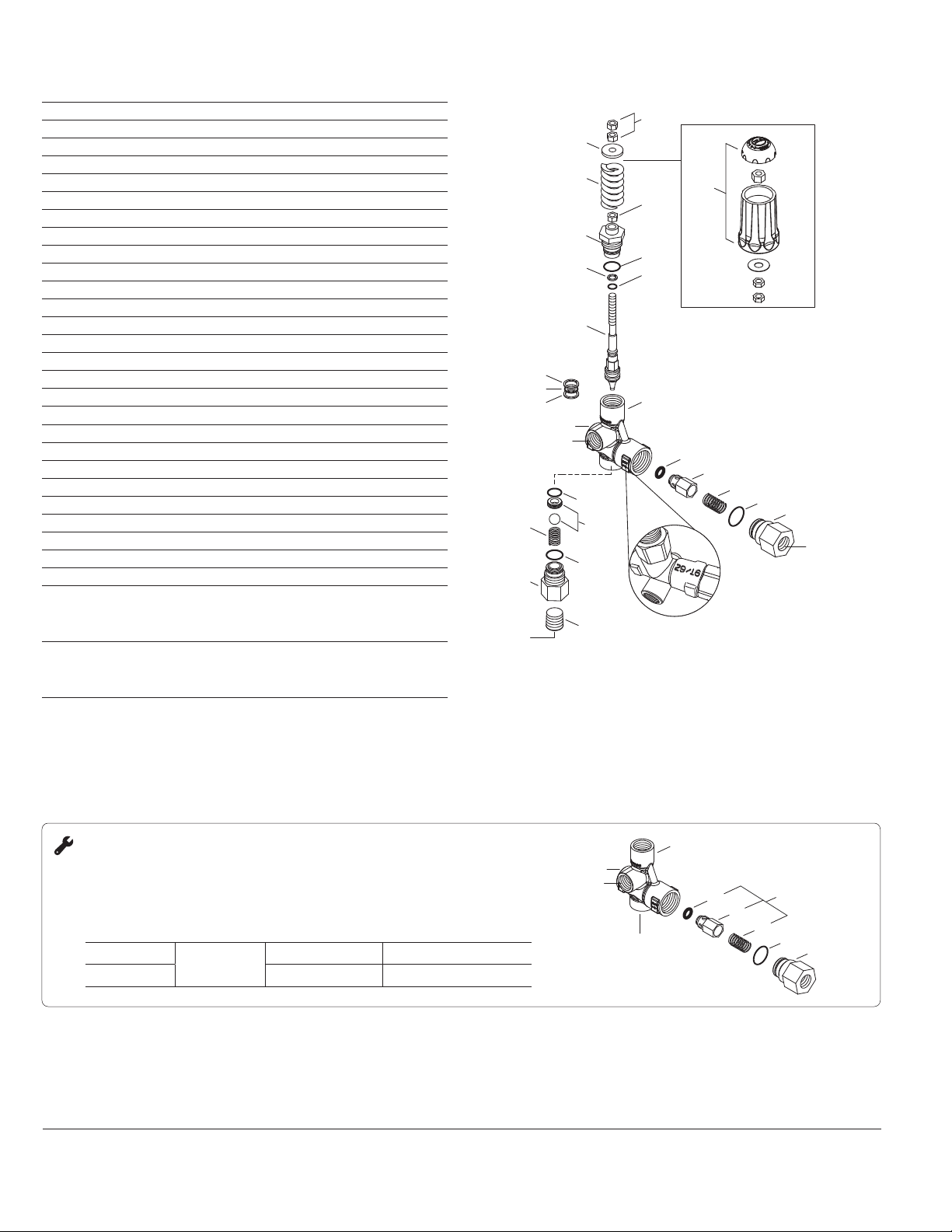
EXPLODED VIEWPARTS LIST
Bold print part numbers are unique to a particular model.
Italics are optional items.
R Components comply with RoHS Directive. MATERIAL CODES (Not Part of Part
Number): BB=Brass FBB=Forged Brass FPM=Fluorocarbon
NBR=Medium Nitrile (Buna-N) PTFE=Pure Polytetrafluoroethylene S=304SS
SS=316SS STCP=Steel/Chrome Plated STL=Steel
To convert to optional handle assembly, remove items 403 (quantity 2), 410 and 409.
Then reassemble as shown in insert.
403
410
408
415
440
409
Bypass
Discharge
441
444
414
412
430
429
430
437
439
462
Inlet
434
455
Date Stamp Location*
Read as week/year
446
460
443
Inlet
402
Optional Adjustment Handle
435
428
425
PN 993368 Rev G 20371 3/21
Inlet
440
Bypass
Discharge
441
444
446
460
443
Inlet
Remove
REGULATING UNLOADER TO RELIEF VALVE CONVERSION
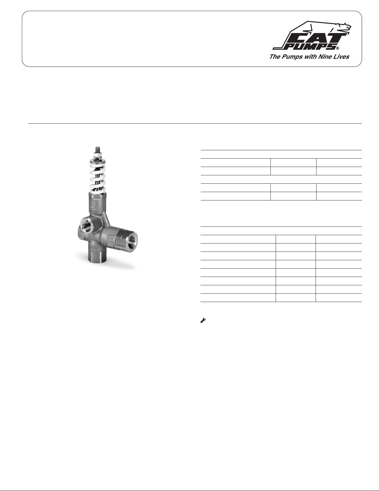
The 7537 and 7542 Pressure-Sensitive Regulating Unloaders are typically used as a primary
pressure regulating device. They can be converted to a Relief Valve to be used as a secondary
pressure relief device by removing the discharge check valve O-ring, and spring.
Unloader PN Modifications Converted Relief Valve PN
7537 Remove parts
441, 443, 444
7537.100 (NBR Seals) 7537.1110 (FPM Seals)
7542 7542.100 (NBR Seals) 7537.1110 (FPM Seals)
CAT PUMPS 1681 94th Lane N.E., Minneapolis, MN 55449-4324 P: (763)780-5440 F: (763)780-2958 E: techsupport@catpumps.com www.catpumps.com
• CAUTIONS AND WARNINGS
All high-pressure systems require a primary pressure regulating device (i.e. regulator, unloader) and a secondary pressure relief device (i.e. pop-off valve, relief valve). Failure to install such
relief devices could result in personal injury or damage to pump or property. Cat Pumps does not assume any liability or responsibility for the operation of a customer’s high-pressure system.
Read all CAUTIONS and WARNINGS before commencing service or operation of any high-pressure system. The CAUTIONS and WARNINGS are included in each Service Manual and with each
Accessory Data sheet. CAUTIONS and WARNINGS can also be viewed online at www.catpumps.com/dynamic-literature/cautions-and-warnings or can be requested directly from Cat Pumps.
WARRANTY
View the Limited Warranty on-line at www.catpumps.com/literature/cat-pumps-limited-warranty
©2021 Cat Pumps Inc. All rights reserved. All data contained in this document are based on the latest product information available at the time of publication. Cat Pumps reserves the right to make changes at any time without notice.
This manual suits for next models
1
Popular Control Unit manuals by other brands

MAYSER
MAYSER SG-RST 204 operating instructions

CEBEK
CEBEK E-8 user manual

Keysight
Keysight M9164A Startup and Service Guide

National Instruments
National Instruments NI PXIe-7975R Getting started guide

Watts
Watts LFM115-2 Installation operation & maintenance

ITT
ITT Engineered Valves CU27 Installation, operation and maintenance manual