Otto Bock 4r136 User manual

4R136
Gebrauchsanweisung �������������������������������������������������������������������� 3
Instructions for Use ������������������������������������������������������������������������ 6
Instructions d‘utilisation ������������������������������������������������������������������ 8
Istruzioni per l’uso ����������������������������������������������������������������������� 11
Instrucciones de uso �������������������������������������������������������������������� 14
Manual de utilização ��������������������������������������������������������������������� 17
Gebruiksaanwijzing ���������������������������������������������������������������������� 20
Bruksanvisning ���������������������������������������������������������������������������� 23
Brugsanvisning ���������������������������������������������������������������������������� 29
Bruksanvisning ���������������������������������������������������������������������������� 29
Käyttöohje ����������������������������������������������������������������������������������� 31
Instrukcja użytkowania ������������������������������������������������������������������ 34
Használati utasítás ����������������������������������������������������������������������� 37
Návod k použití ���������������������������������������������������������������������������� 40
Instrucţiuni de utilizare ������������������������������������������������������������������ 43
Upute za uporabu ������������������������������������������������������������������������ 46
Инструкция за употреба �������������������������������������������������������������� 48
Kullanma talimatı �������������������������������������������������������������������������� 51
Οδηγίες χρήσης �������������������������������������������������������������������������� 54
Руководство по применению ������������������������������������������������������� 57
取扱説明書 ���������������������������������������������������������������������������������� 60
使用说明书 ���������������������������������������������������������������������������������� 63
4R136

2 | Ottobock
123
45

Ottobock | 3
Deutsch
INFORMATION
Datum der letzten Aktualisierung: 2014-08-19
• Lesen Sie dieses Dokument aufmerksam durch.
• Beachten Sie die Sicherheitshinweise.
Bedeutung der Symbolik
HINWEIS Warnungen vor möglichen technischen Schäden.
INFORMATION
Hinweise zur Bedienung. Hinweise für das Service-Personal.
INFORMATION
Der Lieferumfang ist auf der Titelseite abgebildet.
1 Beschreibung
1.1 Verwendungszweck
Das Ottobock Ausstoßventil 4R136 ist ausschließlich zur prothetischen
Versorgung der unteren Extremität einzusetzen.
1.2 Einsatzgebiet
Das Ausstoßventil 4R136 dient, in Verbindung mit einer Kniekappe, der Er
-
zeugung eines Unterdrucks in einem Prothesenschaft. Durch diese Technik
werden Scher- und Reibungskräfte effektiv reduziert.
1.3 Sicherheitshinweise
Bitte geben Sie die nachfolgenden Sicherheitshinweise an Ihre Patienten
weiter:
HINWEIS
Korrosionsgefahr. Prothesenpassteile dürfen keinen Umgebungen aus-
gesetzt werden, die Korrosionen an den Metallteilen auslösen, wie z. B.
Süßwasser, Salzwasser und Säuren.

4 | Ottobock
Bei Einsatz eines Medizinproduktes unter diesen Umgebungsbedingungen
erlöschen alle Ersatzansprüche gegen Otto Bock HealthCare.
HINWEIS
Werden die Montagehinweise nicht befolgt, so kann dies einen kom-
pletten Verlust des unterdrucks zur Folge haben und damit auch einen
1.4 Funktion
Das Ausstoßventil 4R136 drückt in der Standphase überschüssige Luft
aus dem Schaft und schließt in der Schwungphase, damit keine Luft nach-
strömen kann. Durch dieses System werden Scher- und Reibungskräfte
effektiv reduziert.
2 Bauteile
• V4 Ventil 1 St
• Schaftansatzstück, gewinkelt 1 St
• Schaftansatzstück, gerade 1 St
• Schlauch 1 St
• Unterlegscheibe 2 St
3 Handhabung
3.1 Montagevorbereitung
Folgende Werkzeuge werden zusätzlich bei der Montage des Schaftan-
satzstückes benötigt:
• Zange
• 5, 6, 10 mm Bohrer
• 2-Komponenten Epoxyd-Kleber (5 Min. Aushärtezeit) oder Siegelharz-
Talkum-Gemisch
• Isolier- oder Polyethylenband
• 1/4 UNF Gewindeschneider

Ottobock | 5
3.2 Fertigstellung
Den Schaft in gewohnter Weise laminieren. Dann posterior, möglichst
weit distal eine 10 mm Bohrung setzen. Beim Bohren entstandene Grate
entfernen. Von innen mit PE-Band sichern. Das Loch mit Gießharz füllen,
um Luftdichte zu erreichen. (Abb. 1). Ein 5 mm Loch zentral in die Siegel-
harzfüllung bohren und mit einem 1/4 UNF Gewindeschneider das Gewinde
schneiden oder ein 6 mm Loch zentral in die Siegelharzfüllung bohren und
das Gewinde mit Hilfe des Ansatzstückes in das Loch schneiden. Über-
prüfen, dass das Gewindeteil des Ansatzstückes nicht länger ist, als die
Dicke der Wandstärke des Laminats. Gegebenfalls mit Unterlegscheibe
arbeiten (Abb. 2).
Den 2-Komponenten Epoxyd-Kleber oder das Siegelharz-Talkum-Gemisch
anmischen. Eine dünne Schicht der Masse auf das Gewinde des Ansatz-
stückes auftragen (Abb. 3). Vorsicht beim Auftragen des Klebers, dass
kein Kleber in das offene Ende des Ansatzes gelangt.
Das Ansatzstück mit der Zange komplett in die vorbereitete Bohrung dre-
hen (Abb. 4)
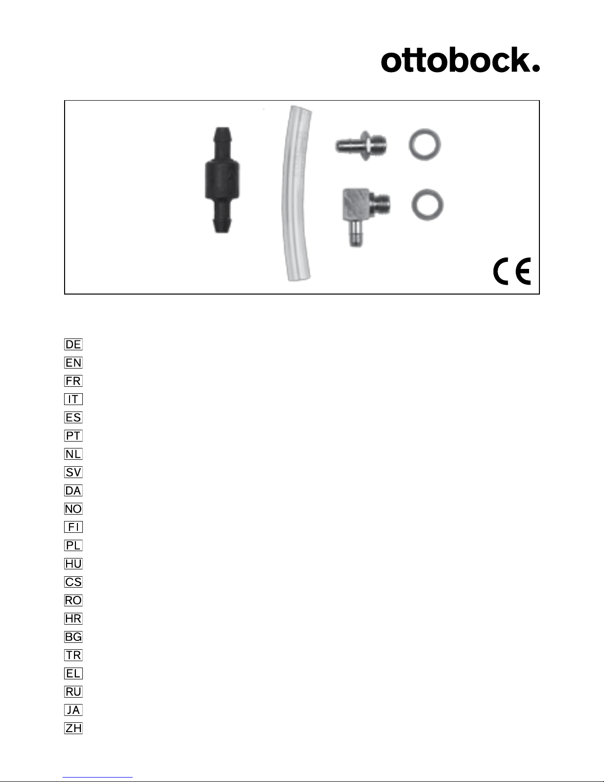
Den Schlauch auf das Ansatzstück führen.
Das Ausstoßventil auf dem Schlauchende montieren. Der Pfeil auf dem
Ventil zeigt die Flussrichtung der Luft an (Abb. 5).
4 Haftung
Der Hersteller haftet, wenn das Produkt gemäß den Beschreibungen und
Anweisungen in diesem Dokument verwendet wird. Für Schäden, die durch
Nichtbeachtung dieses Dokuments, insbesondere durch unsachgemäße
Verwendung oder unerlaubte Veränderung des Produkts verursacht werden,
haftet der Hersteller nicht.
5 CE-Konformität
Das Produkt erfüllt die Anforderungen der Richtlinie 93/42/EWG für Me-
nach Anhang IX der Richtlinie wurde das Produkt in die Klasse I eingestuft.
Die Konformitätserklärung wurde deshalb von Ottobock in alleiniger Ver-
antwortung gemäß Anhang VII der Richtlinie erstellt.

6 | Ottobock
English
INFORMATION
Date of the last update: 2014-08-19
• Please read this document carefully.
• Follow the safety instructions.
Explanation of Symbols
NOTICE Warnings regarding possible technical damage.
INFORMATION
INFORMATION
The scope of delivery is shown on the front page.
1 Description
1.1 Intended use
The Ottobock 4R136 exhaust valve is intended exclusively for use in pros-
1.2 Field of application
In combination with a sealing sleeve, the 4R136 exhaust valve serves to
create a vacuum in a prosthetic socket. Thanks to this technology, shear-
ing and friction forces are effectively reduced.
1.3 Safety instructions
Please make your patients aware of the following safety instructions:
NOTICE
Risk of corrosion. Prosthetic components must not be exposed to sub-
stances which could cause metal parts to corrode, such as fresh water,
salt water and acids.
Using this medical device in such environmental conditions will render
all claims against Otto Bock HealthCare null and void.

Ottobock | 7
NOTICE
Failure to observe the installation instructions can result in complete
1.4 Function
The 4R136 exhaust valve ejects excessive air out of the socket during the
air. Thanks to this system, shearing and friction forces are effectively reduced.
2 Components
• V4 valve, 1 pc.
• Socket connector, angled, 1 pc.
• Socket connector, straight, 1 pc.
• Tube, 1 pc.
• Washer, 2 pcs.
3 Handling
3.1 Installation preparation
The following tools are needed in addition for installing the socket connector:
• Pliers
• 5, 6, 10 mm drill bit
• 2-component epoxy adhesive (5 min. curing time) or sealing resin-talcum
mixture
• Insulating or polyethylene tape
• 1/4 UNF tap
3.2 Completion
Laminate the socket in the usual way. Drill a 10 mm bore hole into the
posterior side of the socket, as close to the distal end as possible. Remove
any burrs caused by drilling. Secure from inside with polyethylene adhesive
tape. Fill the hole with lamination resin to achieve air tightness (Fig. 1). Drill
cut the thread in the hole using the connector. Verify that the thread of the

8 | Ottobock
elbow connector is not longer than the laminate’s wall thickness. If need
be, use a washer (Fig. 2).
Mix the 2-component epoxy adhesive or the sealing resin-talcum mixture.
Apply a thin layer of the mass to the thread of the connector (Fig. 3). When
applying the adhesive, be careful not to let any adhesive get into the open
end of the connector.
Screw the connector fully into the prepared hole using the pliers (Fig. 4).
Slide the tube onto the connector.
Install the exhaust valve on the end of the hose. The arrow on the valve
4 Liability
The manufacturer will only assume liability if the product is used in accordance
with the descriptions and instructions provided in this document. The manufac-
turer will not assume liability for damage caused by disregard of this document,
5 CE conformity
This product meets the requirements of the 93/42/EWG guidelines for medical
declaration of conformity was therefore created by Ottobock with sole
responsibility according to appendix VII of the guidelines.
Français
INFORMATION
Date de la dernière mise à jour: 2014-08-19
• Veuillez lire attentivement l‘intégralité de ce document.
• Respectez les consignes de sécurité.
Signication des symboles
AVIS Mises en garde contre les éventuels dommages techniques.
INFORMATION Autres informations relatives à l’appareillage/ l’utilisation.

Ottobock | 9
INFORMATION
La page de couverture du présent document contient une illustration
des éléments livrés.
1 Description
1.1 Emploi prévu
La soupape de purge 4R136 d’Ottobock est destinée exclusivement à
l’appareillage prothétique des membres inférieurs.
1.2 Domaine d’application
La soupape de purge 4R136 permet, en association avec un protège-genou,
de créer une dépression dans une emboîture prothétique. Cette technique
1.3 Consignes de sécurité
Veuillez communiquer les consignes de sécurité suivantes à vos patients :
AVIS
Risque de corrosion. Les composants prothétiques ne doivent pas être
exposés à des environnements provoquant la corrosion des pièces mé-
talliques, par exemple à de l’eau douce, de l’eau salée et des acides.
Une utilisation du dispositif médical dans ces conditions environnemen-
tales décharge Otto Bock HealthCare de toute responsabilité.
AVIS
Le non-respect des consignes de montage peut entraîner une perte
complète de la dépression et par conséquent une différence d’adhé-
1.4 Fonctionnement
La soupape de purge 4R136 élimine l’excédent d’air de l’emboîture au
les forces de frottement et de cisaillement.

10 | Ottobock
2 Composants
• 1 soupape V4
• 1 embout d’emboîture coudé
• 1 embout d’emboîture droit
• 1 tuyau
• 2 rondelles
3 Manipulation
3.1 Préparation du montage
Les outils suivants sont en outre requis pour monter l’embout d’emboîture :
• Pince
• Forets de 5, 6, 10 mm
• Colle époxy 2 composants (temps de durcissement 5 min) ou mélange
de résine de scellement et talc
• Ruban isolant ou en polyéthylène
• Taraud 1/4 UNF
3.2 Finition
10 mm à l’arrière, le plus loin possible sur le côté distal. Éliminer les écailles
dues à l’alésage. Appliquer un ruban PE à l’intérieur pour consolider. Remplir
trou de 5 mm au centre du bourrage en résine de scellement et créer le
utiliser une rondelle (ill. 2).
Mélanger la colle époxy 2 composants ou le mélange de résine de scelle-
(ill. 3). Veiller à ce que la colle ne coule pas dans l’extrémité ouverte de
l’embout en l’appliquant.
Insérer complètement l’embout dans l’alésage préparé en le faisant tourner
à l’aide de la pince (ill. 4).
Insérer le tuyau sur l’embout.
Table of contents
Languages:
Other Otto Bock Control Unit manuals
Popular Control Unit manuals by other brands

Festo
Festo Compact Performance CP-FB6-E Brief description

Elo TouchSystems
Elo TouchSystems DMS-SA19P-EXTME Quick installation guide

JS Automation
JS Automation MPC3034A user manual

JAUDT
JAUDT SW GII 6406 Series Translation of the original operating instructions

Spektrum
Spektrum Air Module System manual

BOC Edwards
BOC Edwards Q Series instruction manual

KHADAS
KHADAS BT Magic quick start

Etherma
Etherma eNEXHO-IL Assembly and operating instructions

PMFoundations
PMFoundations Attenuverter Assembly guide

GEA
GEA VARIVENT Operating instruction

Walther Systemtechnik
Walther Systemtechnik VMS-05 Assembly instructions

Altronix
Altronix LINQ8PD Installation and programming manual


