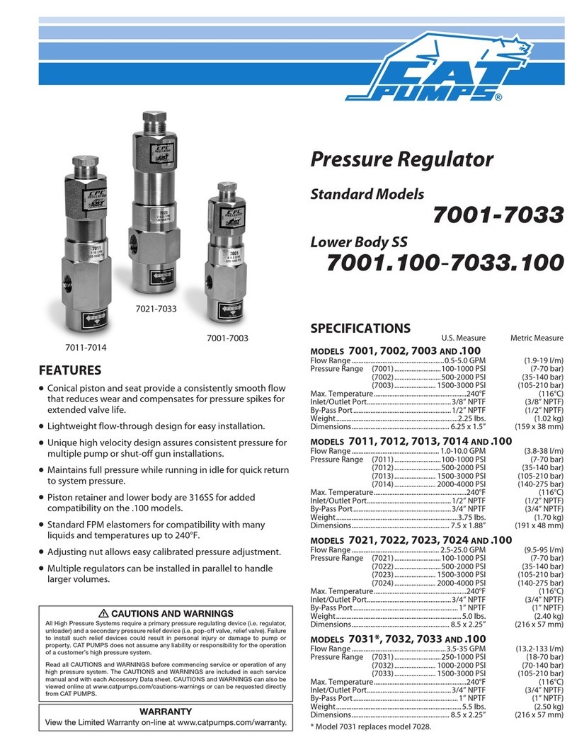
CAT Pumps 7350 User manual

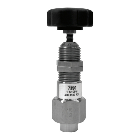
Stainless Steel
Pressure Regulator
Model7350
SPECIFICATIONS
U.S. Measure Metric Measure
Flow Range ...........................................1-12 gpm (3.8-45 l/m)
Pressure Range ..............................400-1500 psi (28-105 bar)
Maximum Temperature ........................... 180°F (82°C)
Inlet Port ................................................1/4” NPTF (1/4” NPTF)
By-Pass Port ..........................................3/8” NPTF (3/8” NPTF)
Weight ....................................................... 1.42 lbs. (0.64 kg)
Dimensions ..............................................2.26 x 6” (56 x 152 mm)
FEATURES
l Maintains full pressure while running in idle for
quick return to system pressure.
l Conical piston and seat provide a consistently
smooth flow that reduces wear and compensates
for pressure spikes for extended valve life.
l Spring set offers precise pressure setting and fast
reaction to system flow changes.
l Minimum pressure fluctuations with the
alternating use of multiple guns and nozzles.
l Top adjusting cup and locking nut to secure
calibrated pressure setting.
l No external moving parts. Stainless Steel and
FPM internal parts for temperature and liquid
compatibility.
All High Pressure Systems require a primary pressure regulating device (i.e. regulator, unloader)
and a secondary pressure relief device (i.e. pop-off valve, relief valve). Failure to install such relief
devices could result in personal injury or damage to pump or property. CAT PUMPS does not
assume any liability or responsibility for the operation of a customer’s high pressure system.
Read all CAUTIONS and WARNINGS before commencing service or operation of any high
pressure system. The CAUTIONS and WARNINGS are included in each service manual and with
each Accessory Data sheet. CAUTIONS and WARNINGS can also be viewed online at
www.catpumps.com/cautions-warnings or can be requested directly from CAT PUMPS.

TYPICAL REGULATOR INSTALLATION
1 Pressure Gauge
2 Relief Valve
Shown as a secondary safety relief valve
3 Pulsation Dampener
4 Pressure Regulator
5 Triplex Plunger Pump
5
1
2
3
INLET
SELECTION
This pressure regulator is designed for systems with single or
multiple pumps, solenoid (gate) valves, nozzles, standard or
“weep” guns.
Note: For multiple pump systems, it is best to use a pressure
regulator not a pressure sensitive regulating unloader.
This regulator should meet both the desired system flow
(combined nozzle flow rate requirement) and the desired system
pressure.
NOTICE: Operation below the minimum flow of the regulator
causes the regulator to cycle or chatter. Operation above the
maximum flows of the regulator causes premature regulator
wear, regulator cycling and prevents attaining desired system
pressure.
INSTALLATION
This regulator operates properly when mounted in any
direction; however, it is preferred to keep the plumbing to
a minimum and the adjusting cap easily accessible. The
best mounting location is directly on the pump discharge
manifold head or in discharge line using a “T” fitting. Flexible,
high pressure hose (minimum single wire braid) should be at least
the size of the regulator ports when plumbing to and from the
regulator.
The inlet connection is located on the side and is a 1/4”
NPTF sized port. Plumb into this port for discharge flow from
the pump.
The by-pass connection is located on the bottom and is a 3/8” NPTF
sized port. By-pass fluid is directed out of this port and can be
routed to a reservoir or to a drain.
OPERATION
This pressure regulator maintains established system pressure in
the discharge line and at the pump head when the trigger gun is
closed, solenoid (gate) valve is closed or the nozzles are clogged,
thus by-passing all unrequired flow. Squeezing the trigger gun
or opening the solenoid (gate) valve allows for a quick return to
established system pressure.
PRESSURE ADJUSTMENT
1. Setting and adjusting the regulator pressure must be done
with the system “on”.
2. Start the system with regulator backed off to the lowest
pressure setting (counterclockwise direction).
3. Squeeze the trigger and read the pressure on the gauge at the
pump.
Note: Do not read the pressure at the gun or nozzle.
4. If more pressure is desired, release the trigger, turn adjusting
cap one quarter turn in clockwise direction.
5. Squeeze the trigger and read the pressure.
6. Repeat this process until desired system pressure is attained.
7. Once the desired system pressure is reached, stop turning the
adjusting cap and thread jam nut down towards upper body
of regulator to lock in place.
NOTICE: A minimum by-pass flow of 5% of the regulator
rated flow is required for proper regulator performance. If the
entire output is directed through the nozzles (zero by-pass)
the “cushioning” feature of the by-pass liquid is eliminated
and the regulator can malfunction or wear prematurely.
8. If desired system pressure cannot be reached, review
TROUBLESHOOTING chart.
9. When servicing existing systems, back off jam nut.
10. Follow adjustment procedures as stated above for new
regulators.
Note: Do not adjust regulators pressure setting to compensate
for a worn nozzle. Check the nozzle as part of the regular
maintenance and replace if worn.
Note: A secondary pressure safety relief device (i.e., pop-off valve,
safety valve) should be used along with this pressure regulator.
Final adjustment for the relief valve should relieve at 200 psi
above the system operating pressure.
BY-PASS
DISCHARGE
4
Read all CAUTIONS and WARNINGS before commencing
service or operation of any high-pressure system

Approximate Gauge Gauge
Pressure Reading Between Between
at Gauge Pump/Unloader Unloader/Gun-Nozzle-Valve
System in operation system pressure system pressure
(gun open)
System in by-pass 200-300 PSI above 200-300 PSI above
(all guns,valves closed) system pressure system pressure
SERVICING
Disassembly:
1. Disconnect by-pass and inlet plumbing from regulator.
2. Remove regulator from pump.
3. Secure lower body of regulator in a vise with adjusting handle
facing upwards.
4. Remove adjusting cap and unthreading from upper body in a
counterclockwise direction.
5. Remove upper body by unthreading from lower body.
6. Remove upper spring retainer, spring set and conical piston.
NOTICE: Exercise extreme caution to avoid contact and damage
to outside diameter and sharp tip of conical piston.
7. Remove lower body from vise and place on flat surface with
by-pass port facing upwards.
8. Using a tool with the same diameter as that of the conical seat
drive out the conical seat and piston retainer.
NOTICE: Exercise extreme caution to avoid contact and damage
to the inside diameter of the piston retainer as well as the outside
diameter and tapered surfaces of the conical seat.
Note: With the regulator completely disassembled, inspect
sealing area where the conical seat and piston retainer makes
contact within the lower body of the regulator for grooves, pitting
and wear. If damage is found, stop the repair and replace with
new lower body or complete new regulator. If not, proceed with
reassembly.
Reassembly:
1. Place lower regulator body with by-pass port facing
downwards in a vise.
2. Lubricate and install o-ring onto outside diameter of conical
seat. Press conical seat down into lower regulator body with
tapered surface facing upwards.
3. Lubricate and install o-ring onto piston retainer. Press piston
retainer with larger diameter facing downwards.
4. Place conical piston on a flat surface with sharp point facing
upwards. Lubricate and install backup-ring, then o-ring
onto outside diameter of conical piston. Lubricate outside
diameter of conical piston.
5. Press conical piston with sharp point down into piston
retainer.
6. Place upper body with large opening facing up.
7. Drop spring retainer into cap, ensuring spring pilot faces up.
8. Drop in 28 spring washers, alternating direction per exploded
view on the last page.
Note: A small rod such as an ink pen can be used to guide the
washers into the cap to ensure proper orientation is maintained.
9. Invert lower body assembly onto upper body and thread
together.
10. Thread adjusting cap into upper body
11. Re-install regulator onto pump.
12. Reconnect by-pass and inlet plumbing to regulator.
13. Proceed to PRESSURE ADJUSTMENT.
TROUBLESHOOTING
Cycling/Chattering l Too little flow for valve specifications.
l Air in system, poor connections.
l Inlet seals in pump worn.
l O-ring in gun worn.
System will not l Nozzle worn.
build up to pressure l Improper nozzle size for system specs.
l Foreign material trapped in seat.
Pressure drop l Nozzles worn.
l Piston and seat in regulator worn.
l Air in system, poor connections.
l Insufficient flow to pump.
l Filter clogged. Check and clean
regularly.
Pressure spikes l Minimum by-pass of 5% not present.
while in by-pass l Excessive pressure adjustment
made for worn nozzle. REPLACE
NOZZLE. Reset system pressure.
Leakage from l O-ring around piston worn or piston
regulator vent hole retainer scored. Service with o-ring kit.
Read all CAUTIONS and WARNINGS before commencing
service or operation of any high-pressure system

EXPLODED VIEW PARTS LIST
ITEM P/N MATL DESCRIPTION QTY
401 30161 — Cap, Adjusting, Assembly 1
(Inclds: Cap, Stud, Jam Nut)
406 30541 STNP Body, Upper 1
408 76229 STL Spring Set 1
410 30726 BB Retainer, Spring 1
418 30566 SSB Piston, Conical 1
427 31488 SS Retainer, Piston 1
436 76724 SSB Seat, Conical 1
440 30538 SS Body, Lower 1
468 30749 FPM Kit, O-Ring 1
490 34090 STL Panel Mount Assy (Inclds: 2 Jam Nuts) 1
Italics are optional items.
MATERIAL CODES (Not Part of Part Number):
BB=Brass FPM=Fluorocarbon SS=316SS
SSB=316SS Condition B STL=Steel STNP=Steel Nickel Plated
CAT PUMPS
1681 - 94TH LANE N.E. MINNEAPOLIS, MN 55449-4324
PHONE (763) 780-5440 — FAX (763) 780-2958
e-mail: techsupport@catpumps.com
www.catpumps.com
For International Inquiries go to www.catpumps.com and navigate to the “Contact Us” link.
PN 993367 Rev A 12/10 121002
490
401
468
436
440
468
427
468
418
408
410
406
By-Pass Port
3/8 - 18 NPT
Inlet Port
1/4 - 18 NPTF
Other CAT Pumps Controllers manuals
Popular Controllers manuals by other brands

Johnson Controls
Johnson Controls VG1600 Series installation instructions

VS LIGHTING SOLUTIONS
VS LIGHTING SOLUTIONS Blu2Light MultiSensor XXL quick start guide

Contrec
Contrec 515 Operation manual

DSE
DSE 334 ATS Operator's manual

Coremorrow
Coremorrow Modular E70 Series user manual

Powerhouse Dynamics
Powerhouse Dynamics SiteSage installation guide

Hobby King
Hobby King 70A Boat manual

EQ3
EQ3 HmIPW-DRS4 Installation instructions and operation manual

HYDRO-RAIN
HYDRO-RAIN HRC 390 SERIES Quick start instructions

Elko
Elko iNels SA3-04M instructions

Buspro
Buspro HDL-MHRCU.433 user manual

Screen Innovations
Screen Innovations LinkPro Z installation instructions