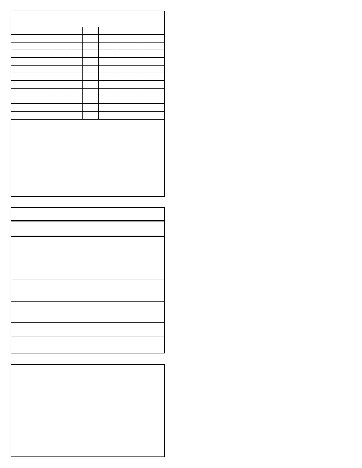
TORQUE CHART
Pump Item Torque
Pump Model Thread Tool Size [P/N] in.lbs. ft.lbs. Nm
Plunger Retainer
781 M5 M11 Hex 55 4.4 6
2831 M7 M14 Hex 90 7.2 10
Inlet/Discharge Manifold Screws
781 M10 M8 Allen [33046] 250 20.8 28
2831 M12 M10 Allen [33047] 355 29.6 40
Valve Block Manifold Screws
781 M10 M8 Allen [33046] 250 20.8 28
2831 M12 M10 Allen [33047] 355 29.6 40
Crankcase Cover/Bearing Cover Screws
781 M6 M10 Hex [25082] 115 9.4 13
2831 M8 M13 Hex [25324] 115 9.4 13
Connecting Rod Screws
781, 2831 M8 M13 Hex [25324] 130 10.8 15
Bubble Oil Gauge
781, 2831 M28 Oil Gauge Tool [44050] 45 3.6 5
PREVENTATIVE MAINTENANCE CHECK-LIST
Check Daily Weekly 50 hrs. 500 hrs.* 1500 hrs.** 3000 hrs.**
Clean Filters x
Oil Level/Quality x
Oil Leaks x
Water Leaks x
Belts, Pulley x
Plumbing x
Initial Oil Change x
Oil Change x
Seal Change x
Valve Change x
Accessories x
TECHNICAL BULLETIN REFERENCE CHART
No. Subject Models
002 Inlet Pressure VS Liquid Temperature All Models
003 Power Unit Drive Packages 3PFR - 68PFR, 10FR - 60FR
024 Lubrication of Lo-Pressure Seals All Models
035 Servicing Crankcase Section 7PFR - 60PFR
036 Cylinder and Plunger Reference Chart All Models
043 LPS and HPS Servicing All Plunger Models
053 Liquid Gasket All Plunger NAB-S.S. Models
064 By-Pass Hose Sizing All Unloaders/Regulators
074 Torque Chart Piston and Plunger Pumps
077 Oil Drain Kit All Models (except 2SF/4SF)
083 Winterizing a Pump All Models
085 M8 Keyway 25FR, 25PFR, 28PFR
* If other than CAT PUMPS special multi-viscosity ISO68 oil is used,
change cycle should be every 300 hours.
** Each system’s maintenance cycle will be exclusive. If system per-
formance decreases, check immediately. If no wear at 1500 hours,
check again at 2000 hours and each 500 hours until wear is ob-
served. Valves typically require changing every other seal change.
Duty cycle, temperature, quality of pumped liquid and inlet feed
conditions all effect the life of pump wear parts and service cycle.
** Remember to service the regulator/unloader at each seal servicing
and check all system accessories and connections before resuming
operation.
INLET CONDITION CHECK-LIST
Review Before Start-Up
Inadequate inlet conditions can cause serious malfunctions in the best designed
pump. Surprisingly, the simplest of things can cause the most severe problems or go
unnoticed to the unfamiliar or untrained eye. REVIEW THIS CHECK-LIST BEFORE
OPERATION OF ANY SYSTEM. Remember, no two systems are alike, so there can
be no ONE best way to set-up a system. All factors must be carefully considered.
INLET SUPPLY should exceed the maximum flow being delivered by the pump to
assure proper performance.
❏Open inlet shut-off valve and turn on water supply to avoid starving pump.
DO NOT RUN PUMP DRY.
❏Temperatures above 130°F are permissible. Add 1/2 PSI inlet pressure per each
degree F over 130°F. Elastomer or RPM changes may be required. See Tech
Bulletin 002 or call CAT PUMPS for recommendations.
❏Avoid closed loop systems especially with high temperature, ultra-high pressure
or large volumes. Conditions vary with regulating/unloader valve.
❏Low vapor pressure liquids, such as solvents, require a booster pump and C.A.T.
to maintain adequate inlet supply.
❏Higher viscosity liquids require a positive head and a C.A.T. to assure adequate
inlet supply.
❏Higher temperature liquids tend to vaporize and require positive heads and
C.A.T. to assure adequate inlet supply.
❏When using an inlet supply reservoir, size it to provide adequate liquid to accom-
modate the maximum output of the pump, generally a minimum of 6-10 times the
GPM (however, a combination of system factors can change this requirement);
provide adequate baffling in the tank to eliminate air bubbles and turbulence;
install diffusers on all return lines to the tank.
INLET LINE SIZE should be adequate to avoid starving the pump.
❏Line size must be a minimum of one size larger than the pump inlet fitting. Avoid
tees, 90 degree elbows or valves in the inlet line of the pump to reduce the risk of
flow restriction and cavitation.
❏The line MUST be a FLEXIBLE hose, NOT a rigid pipe, and reinforced on SUCTION
systems to avoid collapsing.
❏The simpler the inlet plumbing the less the potential for problems. Keep the
length to a minimum, the number of elbows and joints to a minimum (ideally no
elbows) and the inlet accessories to a minimum.
❏Use pipe sealant to assure air-tight, positive sealing pipe joints.
INLET PRESSURE should fall within the specifications of the pump.
❏Acceleration loss of liquids may be increased by high RPM, high temperatures,
low vapor pressures or high viscosity and may require pressurized inlet and
C.A.T. to maintain adequate inlet supply. DO NOT USE C.A.T. WITH SUCTION
INLET.
❏Optimum pump performance is obtained with +20 PSI (1.4 BAR) inlet pressure
and a C.A.T. for certain applications. With adequate inlet plumbing, most pumps
will perform with flooded suction. Maximum inlet pressure is 70 PSI (4.9 BAR).
❏After prolonged storage, pump should be rotated by hand and purged of air to
facilitate priming. Disconnect the discharge port and allow liquid to pass through
pump and measure flow.
❏“K” versions are suitable for high inlet pressures. Consult CAT PUMPS.
INLET ACCESSORIES are designed to protect against over pressurization, control
inlet flow, contamination or temperature and provide ease of servicing.
❏A shut-off valve is recommended to facilitate maintenance.
❏Installation of a C.A.T. is essential in applications with stressful conditions such
as high temperatures, booster pump feed or long inlet lines. Do not use C.A.T.
with negative inlet pressure.
❏A stand pipe can be used in some applications to help maintain a positive head
at the pump inlet line.
❏Inspect and clean inlet filters on a regular schedule to avoid flow restriction.
❏A pressure transducer is necessary to accurately read inlet pressure. Short
term, intermittent cavitation will not register on a standard gauge.
❏All accessories should be sized to avoid restricting the inlet flow.
❏All accessories should be compatible with the solution being pumped to prevent
premature failure or malfunction.
❏Optional inlet protection can be achieved by installing a pressure cut off switch
between the inlet filter and the pump to shut off pump when there is no positive
inlet pressure.
❏“K” versions are suitable for high temperatures and containment of harmful
liquids. Consult CAT PUMPS for optional flushing and cooling accessory.
BY-PASS TO INLET Care should be exercised when deciding the method of by-pass
from control valves.
❏It is recommended the by-pass be directed to a baffled reservoir tank, with at
least one baffle between the by-pass line and the inlet line to the pump.
❏Although not recommended, by-pass liquid may be returned to the inlet line of the
pump if the system is properly designed to protect your pump. When a pulsation
dampener is used, a PRESSURE REDUCING VALVE must be installed on the
inlet line (BETWEEN THE BY-PASS CONNECTION AND THE INLET TO THE
PUMP) to avoid excessive pressure to the inlet of the pump. It is also recommend-
ed that a THERMO VALVE be used in the by-pass line to monitor the temperature
build-up in the by-pass loop to avoid premature seal failure.
❏A reinforced, flexible, low pressure hose rated up to 300 PSI should be used for
routing by-pass back to the pump inlet.
❏Caution should be exercised not to undersize the by-pass hose diameter and
length. Refer to Technical Bulletin 064 for additional information on the size and
length of the by-pass line.
❏Check the pressure in the by-pass line to avoid over pressurizing the inlet.
❏The by-pass line should be connected to the pump inlet line at a gentle angle of
45° or less and no closer than 10 times the pump inlet port diameter e.g. 1-1/2"
port size = 15" distance from pump inlet port.