Cattron RAC16 User manual

1
RAC16
User Guide
9M02-9029-A001-EN
Rev. 4
RAC16
Programmer
User Guide
9M02-9029-A001-EN

2
RAC16
User Guide
9M02-9029-A001-EN
Rev. 4
Revision History
VERSION
DATE
NOTES
3
5/2/2019
Updated Branding and expanded Configuration programming
4
7/19/2019
Clarified OCU timeout and added PW

3
RAC16
User Guide
9M02-9029-A001-EN
Rev. 4
Description
The RAC16A Programmer (Figure 1), incorporates an LCD display and membrane keypad plus an
electrical cable to connect to the OCU or MCU that is being programmed, it can be used to read
or change the ID Code, (frequency and address) and change the OCU time-out.
FIGURE 1. RAC16A PROGRAMMER

4
RAC16
User Guide
9M02-9029-A001-EN
Rev. 4
FIGURE 2. RAC16A MENU AND FUNCTIONS
NOTE: Only MCU options will be available when the programmer is connected to an MCU. Likewise, only OCU
options will be available when the programmer is connected to an OCU.
Sequence items highlighted in Red on the left are not available

5
RAC16
User Guide
9M02-9029-A001-EN
Rev. 4
Connecting the Programmer
OCUs have a four position (three plus Key) connector; MCUs have a six-position (five plus Key) connector. The
programmer has a six-position (five plus Key) connector. See Figure 3.
FIGURE 3. THREE AND SIX POSITION CONNECTORS
Locate the programming connector on the OCU or MCU and connect the plug from the
programmer, the plug is polarized and must be aligned as shown above.
FIGURE 4. RAC16 CONNECTED TO OCU FIGURE 5. RAC16 CONNECTED TO MCU

6
RAC16
User Guide
9M02-9029-A001-EN
Rev. 4
Programming Procedure
If programming an OCU, ensure that the batteries are installed.
If programming an MCU, ensure that power is on (power LED is ON) and note that power can be
supplied from the programming box so separate power is not needed.
Identity Codes
The Identity (ID) Code is a six-digit alphanumeric code (e.g., 2E005B) that contains the operating
frequency and address of the unit. These are hexadecimal numbers that range from 0 to 9 and
A through F.
The first two characters in the six-digit code designate one of the 81 operating frequencies.
•
Each system in a facility should be assigned a different frequency. Figure 6 lists the
frequency for each code.
The last four characters in the six-digit code are the address code.
•
Each system in a plant must have a separate ID Code.
Rules for Assigning ID Codes
•It is important to control the assignment of the unit ID Codes, Cattron accepts no
responsibility for any consequences that result of failure to do so.
oIf frequencies are duplicated it can result in systems shutting down or
operating erratically.
oIf an address is duplicated it could result in an adjacent system being
unintentionally controlled and result in any possible safety
consequence, including damage to machinery, injury and death.

7
RAC16
User Guide
9M02-9029-A001-EN
Rev. 4
Programming
If the programmer is not already switched on, apply power on by pressing the ON button. The
display will show what device the programmer is connected to (OCU or MCU) for 5-seconds and
then will read and display the ID Code of the unit.
Note Relative to Configuration Changes
If you will be changing the configuration but retaining the existing ID Code
(Frequency and Address) you need to record the current value so it can be re-
programmed after the configuration has been changed.
Changing the ID Code
Enter the new 6-digit ID Code for the unit to be programmed. Verify the number on the LCD
display. If a mistake is made when entering the code, the BKSP/ESC key will reposition the cursor
to allow corrections.
ACTION
RAC16A DISPLAY
Enter the new 6-digit ID Code for the device being programmed.
ID CODE 28008C
After the new ID Code is entered, press PRG. (If an error
message is displayed, press MENU or BKSP/ESC to return to
the TX CONNECTED menu.)
SUCCESS!
Verify the new ID Code by connecting the RAC16A as explained above. The ID Code will appear
in the display.

8
RAC16
User Guide
9M02-9029-A001-EN
Rev. 4
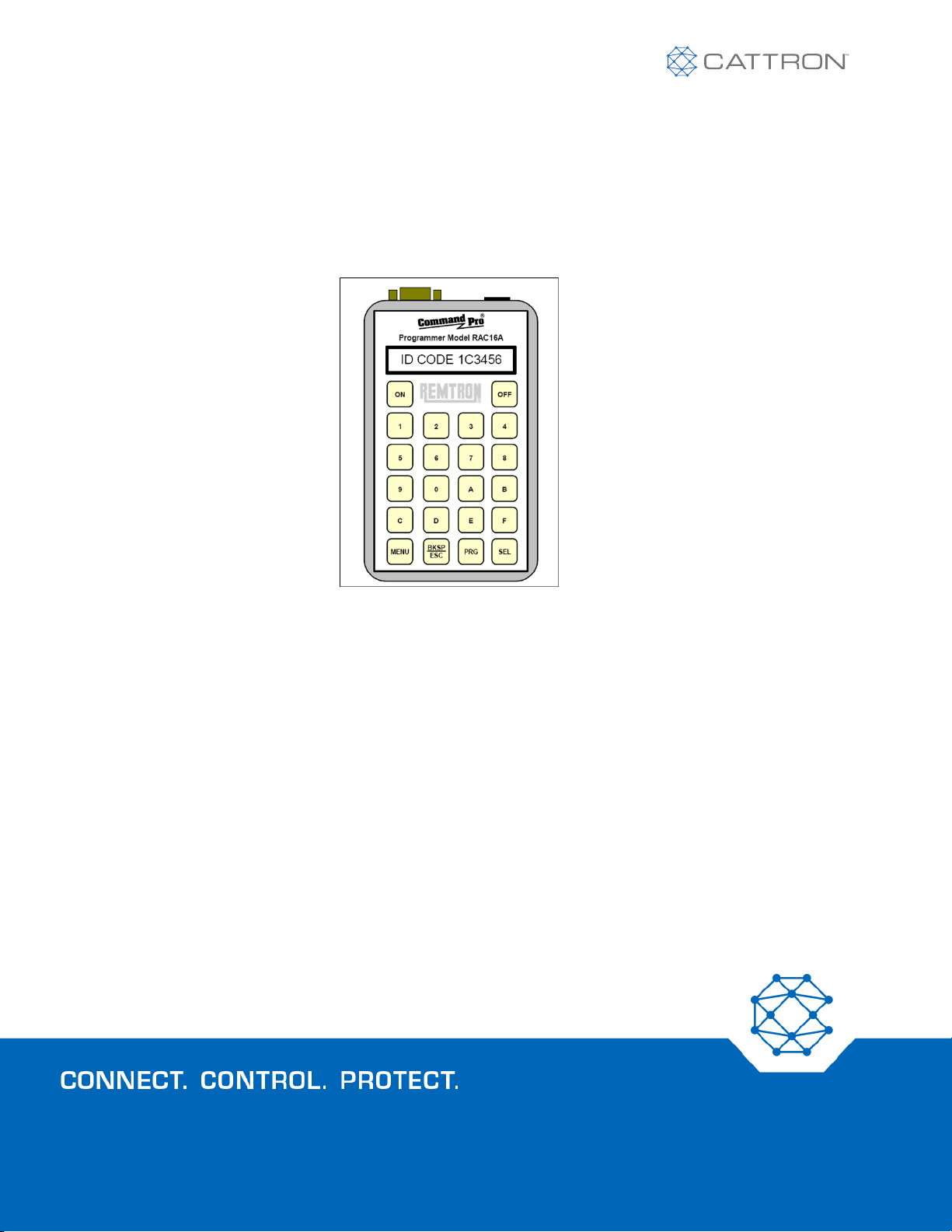
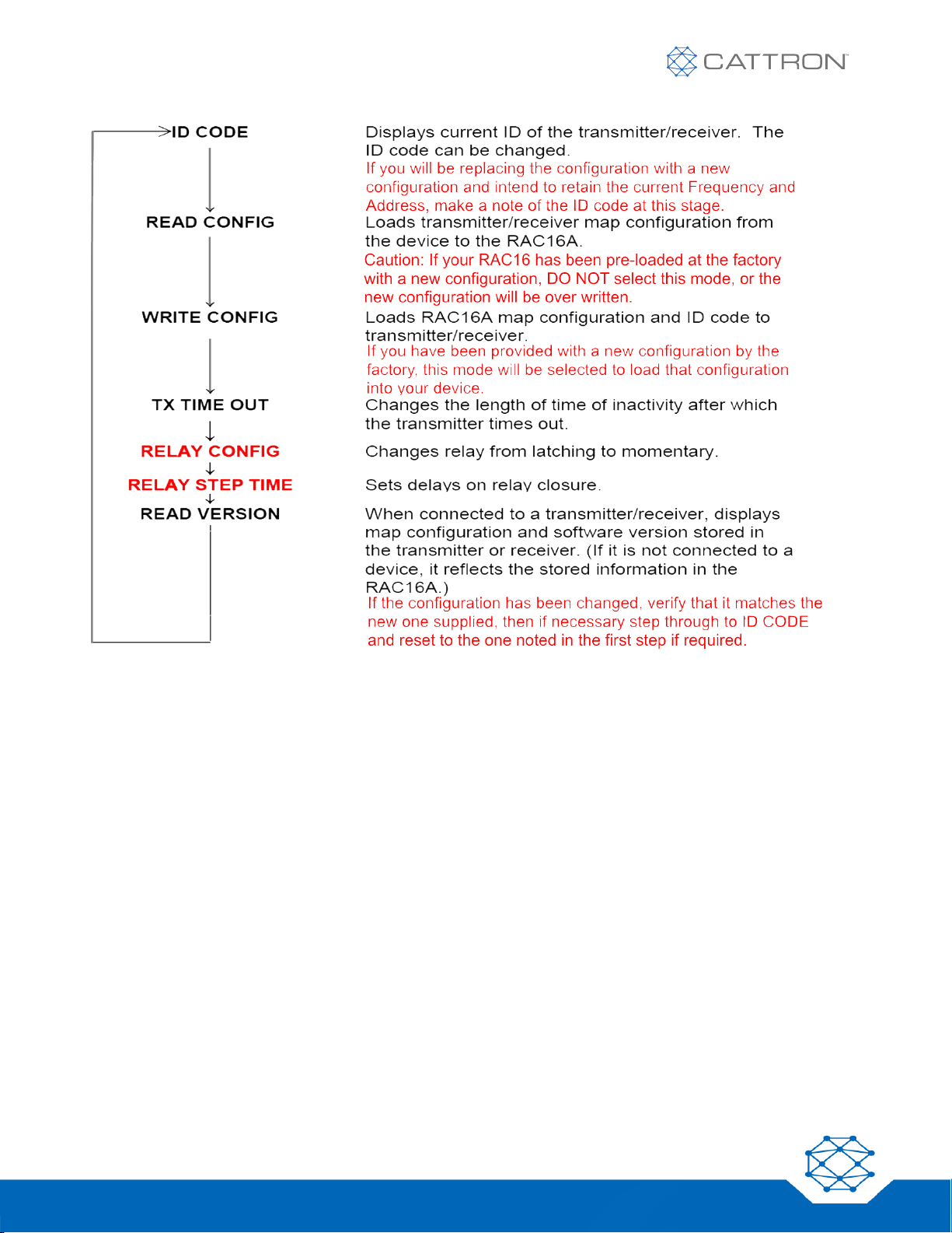
Changing the Configuration
New Factory Supplied Configuration within a RAC16
If a new configuration has been supplied by the factory, make sure you have recorded the original
ID code at step one, then the new configuration can be programmed into your device at this
stage, the RAC16 display will confirm a successful download.
Step through to the READ VERSION step and confirm the loaded configuration matches the new
one supplied.
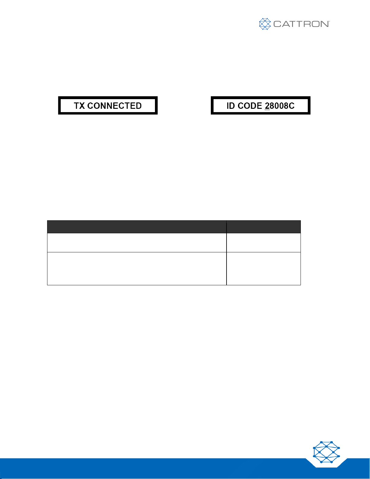
Be sure to then step through to step one and reprogram the ID code, then verify the new ID Code
by re-connecting the RAC16A as explained above. The ID Code will appear in the display.
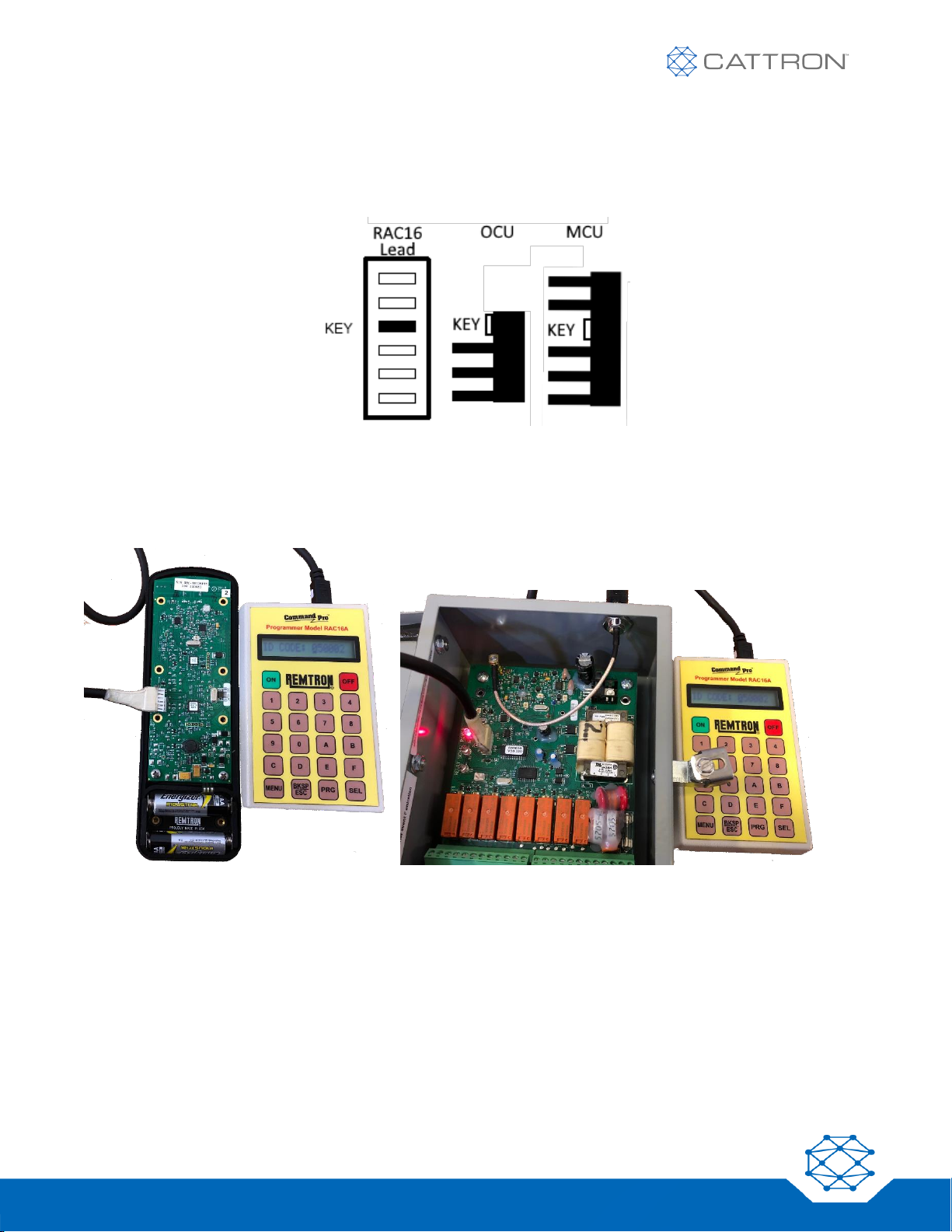
Copying the Configuration from one Unit to Another
Connect a RAC16 to the unit containing the desired configuration and step through to READ
CONFIG, enter password when prompted ‘916’.
Disconnect from that unit and connect the RAC16 to the unit that will be re-programmed
(WARNING THIS IS NOT REVERSABLE), record the current ID code, then step through to WRITE
CONFIG and enter, the RAC should report SUCCESS. If necessary, step through to the ID CODE
section and re-enter the correct ID code.

9
RAC16
User Guide
9M02-9029-A001-EN
Rev. 4
OCU Time-Out
The OCU ‘time-out’ is a battery-saving feature that turns off the OCU after a predetermined time
of inactivity. This time is adjustable from 0 to 60 minutes, with 0 being no time-out.
NB: The selection of maintained transmission or momentary transmission operation is defined
within the Configuration parameters above.
ACTION
RAC16A DISPLAY
Press the MENU button on the RAC16A until the display shows: TX TIME-OUT:
XX
TX TIME-OUT: XX
(XX represents the
current time-out value
(in minutes) of the
connected OCU.)
Enter the new value from 01 to 60.
(00 will not time-out the OCU and require it to be shut off manually.)
PROGRAM TX
CONFIG?
PROGRAM RX
CONFIG?
Press PRG button on the RAC16A.
(If an error message is displayed, press MENU or BKSP/ESC to return to the
TX CONNECTED menu.)
SUCCESS!

10
RAC16
User Guide
9M02-9029-A001-EN
Rev. 4
FREQ
CODE
FREQ
CODE
FREQ
CODE
FREQ
CODE
903.0
03
909.3
18
915.6
2D
921.9
42
903.3
04
909.6
19
915.9
2E
922.2
43
903.6
05
909.9
1A
916.2
2F
922.5
44
903.9
06
910.2
1B
916.5
30
922.8
45
904.2
07
910.5
1C
916.8
31
923.1
46
904.5
08
910.8
1D
917.1
32
923.4
47
904.8
09
911.1
1E
917.4
33
923.7
48
905.1
0A
911.4
1F
917.7
34
924.0
49
905.4
0B
911.7
20
918.0
35
924.3
4A
905.7
0C
912.0
21
918.3
36
924.6
4B
906.0
0D
912.3
22
918.6
37
924.9
4C
906.3
0E
912.6
23
918.9
38
925.2
4D
906.6
0F
912.9
24
919.2
39
925.5
4E
906.9
10
913.2
25
919.5
3A
925.8
4F
907.2
11
913.5
26
919.8
3B
926.1
50
907.5
12
913.8
27
920.1
3C
926.4
51
907.8
13
914.1
28
920.4
3D
926.7
52
908.1
14
914.4
29
920.7
3E
927.0
53
908.4
15
914.7
2A
921.0
3F
908.7
16
915.0
2B
921.3
40
909.0
17
915.3
2C
921.6
41
FIGURE 6. TABLE OF FREQUENCY CODES

11
RAC16
User Guide
9M02-9029-A001-EN
Rev. 4
Due to continuous product improvement, the information provided in this document is subject to change without notice.
Cattron Wireless Automation and Control Solutions Support
For remote and communication control systems support, parts and repair, or technical support, visit us online at:
www.cattron.com/wacs-support
Safe-E-Stop™ is manufactured at the following location:
Cattron North America Inc., 655 N River Rd NW, Suite A, Warren, OH 44483
Cattron property and confidential
9M02-9029-A001-EN
Rev. 4
Due to continuous product improvement, the information provided in this document is subject to change without notice.
Cattron Support
For remote and communication control systems support, parts and repair, or technical support, visit us online at:
www.cattron.com/wacs-support
Safe-E-Stop™ is manufactured at the following location:
Cattron North America Inc., 655 N River Rd NW, Suite A, Warren, OH 44483
Table of contents
Popular Motherboard manuals by other brands

Supermicro
Supermicro H12DSU-iN user manual

Texas Instruments
Texas Instruments DRV8701EVM user guide

Biostar
Biostar TZ77XE4 user manual

ON Semiconductor
ON Semiconductor NCP5106B Series user manual

Delta-q
Delta-q QuiQ-dci Instructions for using

National Semiconductor
National Semiconductor LMH1981 instruction manual