CATU MX-720 User manual

MX-720
MANUEL D’UTILISATION
INSTRUCTION MANUAL
BEDIENUNGSANLEITUNG
MANUAL DE INSTRUCCIONES
MANUAL DE INSTRUÇÕES
MANUALE D’ISTRUZIONI
INSTRUCTIEHANDLEIDING
INSTRUKTIONSMANUAL
BRUGSANVISNING
BRUKSANVISNING
INSTRUKCJA UZYTKOWANIA
KULLANIM KILAVUZU
RoHS
European Low Voltage 2014/35/EU
EN 61010-1:2010 + A1 (2019)
IEC 61326-1:2012
EN 61326-1:2013
IEC 61326-2-1:2012
EN 61326-2-1:2013

2
TEST
LOCK
CONTINUOUS
ZERO
HOLD
MAX/MIN
OFF
CAT III 1000V
1000
V
500V
125V 400Ω
250V 1000V
750V
1
2
3
5
6
8
7
10
4
9
1Affichage digital Digital display Digitale Anzeige Pantalla digital Ecrã digital Display digitale
2
Bouton de
maintien des
données ; MAX/
MIN
Data Hold Knopf;
MAX/MIN
Data Hold Knopf;
MAX/MIN Botón retener
datos; MÁX/MÍN Botão de retenção
de dados; MAX/
MIN
Pulsante di
conservazione dei
dati; MAX/MIN
3Bouton de
verrouillage Lock Button Sperrtaste Botón de bloqueo Botão de bloqueio Pulsante di blocco
4Bouton de
rétro-éclairage ;
ZERO
Backlight Button;
ZERO
Hintergrund-
beleuchtung
Taste; NULL
Botón de
retroiluminación;
CERO
Botão de luz de
fundo; ZERO
Pulsante di
retroillumina
-zione; ZERO
5Bouton de test Test Button Test-Taste Botón de prueba Botão de teste Pulsante di test
6Commutateur
rotatif de
fonction
Rotary Function
Switch
Drehbarer
Funktions
schalter
Botón de función
giratoria
Comutador rotativo
de funções Manopola
funzione
7Prise « VΩ » VΩ Jack VΩ-Buchse Toma VΩ Terminal VΩ Jack VΩ
8Prise d’entrée
COM COM input jack COM-
Eingangs-
buchse
Conector de
entrada COM Terminal de entrada
COM Presa di ingresso
COM
9Fixation Pothook Pothook Gancho Gancho de suporte Gancio di
sospensione
10 Couvercle de la
batterie Battery Cover Haken oder
Aufhängung Tapa de las pilas Tampa das pilhas Coperchio della
batteria

3
TESTEUR D’ISOLATION NUMÉRIQUE
INFORMATIONS DE SÉCURITÉ
• Lisez attentivement les informations de sécurité suivantes
avant d’essayer d’utiliser ou de réparer le testeur.
• Pour éviter d’endommager l’instrument, ne pas appliquer les
signaux qui dépassent les limites maximales indiquées dans
les tableaux de spécifications techniques.
• N’utilisez pas le testeur ou les cordons de test s’ils semblent
endommagés. Soyez extrêmement prudent lorsque vous
travaillez à proximité de conducteurs nus ou de barres
conductrices.
• Un contact accidentel avec le conducteur peut entraîner un
choc électrique.
• N’utilisez l’instrument que de la manière spécifiée dans ce
manuel ; dans le cas contraire, la protection fournie par
l’instrument peut être altérée.
• Lisez le mode d’emploi avant de l’utiliser et suivez toutes les
informations de sécurité.
• Faites attention lorsque vous travaillez avec des tensions
supérieures à 60 V CC ou 30 V CA RMS. De telles tensions
présentent un risque de choc électrique.
• Avant d’effectuer des mesures de résistance ou de
tester la continuité acoustique, déconnectez le circuit de
l’alimentation principale et toutes les charges du circuit.
SYMBOLES DE SÉCURITÉ :
• Attention, consultez ce manuel avant d’utiliser
l’instrument.
• Tensions dangereuses.
• L’équipement est entièrement protégé par une double
isolation ou une isolation renforcée.
• Lors de l’entretien de l’appareil de mesure, utilisez
uniquement les pièces de rechange spécifiées.
• CE Conforme à la norme EN-61010-1
1. SPÉCIFICATIONS
1-1 INFORMATIONS GÉNÉRALES
Conditions environnementales :
• Catégorie de l’installation III
• Degré de pollution 2
• Altitude jusqu’à 2 000 mètres
• Utilisation intérieure uniquement
• Humidité relative 80 % max.
• Température de fonctionnement 0~40 ºC
Maintenance et nettoyage :
• Les réparations ou l’entretien non couverts par ce manuel ne
doivent être effectués que par du personnel qualifié.
• Essuyez régulièrement le boîtier avec un chiffon humide.
N’utilisez pas d’abrasifs ni de solvants sur ces instruments.
1Digitale display Digital Display Digitalt display Digital skjerm Wyświetlacz
cyfrowy
Dijital Ekran
2Data Hold-knop;
MAX/MIN Data PAUSKNAPP;
MAX/MIN Data Hold-knap;
MAKS/MIN
Data hold-
knapp; MAKS/
MIN
Przycisk
zatrzymania
danych; MAKS/
MIN
Veri Tutma
Düğmesi: MAKS/
MİN
3Vergrendelknop Låsknapp Låseknap Låseknapp Przycisk
blokujący
Kilitleme
Düğmesi
4Verlichtingsknop;
nulafstellingsknop
Bakgrunds-
belysningsknapp;
NOLL
Knap til
baggrunds-
belysning; NUL
Baklysknapp;
NULL
Przycisk
podświetlenia;
ZEROWANIE
Arka Işık
Düğmesi: SIFIR
5Testknop Testknapp Testknap Testknapp Przycisk
testowy Test Düğmesi
6Functieschakelaar Roterande
funktionsreglage Drejefunktions-
kontakt Roterende
funksjonsbryter
Obrotowy
przełącznik
funkcji
Döner Fonksiyon
anahtarı
7VΩ klem VΩ uttag VΩ-stik VΩ-kontakt Gniazdo VΩ VΩ Jakı
8COM-ingangsklem COM ingångsuttag COM-
indgangsstik COM-inngangs-
kontakt
Gniazdo
wejściowe COM COM giriş jakı
9Bevestigingshaak Spiskrok Kartoffelkroge Grytekrok Hak do
zawieszenia
S şeklinde
çengel
10 Batterijdeksel Batterilucka Batteridæksel Batterideksel Pokrywa baterii Pil Kapağı

4
Affichage :
• Grand écran LCD avec double affichage
La gamme de mesure est :
• 4 000MΩ/125V, 4 000MΩ/250V, 4 000MΩ/500V, 4
000MΩ/1000V, 400Ω/BZ, 1 000V/DCV. 750 V/ VCA
Taux d’échantillonnage :
• 2,5 fois par seconde.
Réglage du zéro :
• Réglage automatique.
• Indicateur de dépassement de capacité :« OL » le chiffre le
plus élevé est affiché.
Indication de batterie faible :
• Le pictogramme s’affiche lorsque la tension de la
batterie est en dessous de la tension de fonctionnement.
Température de fonctionnement :
• De 0 ºC à 40 ºC (32 ºF à 104 ºF) et humidité inférieure
à 80 % RH
Température de stockage :
• De -10 ºC à 60 ºC (de 14 ºF à 140 ºF) et humidité inférieure
à 70 % RH
Source d’alimentation :
• 9 V CC (6 x 1,5 V pile « AA » ou équivalent)
Dimensions :
• 200(L) x 92(P) x 50(H) mm
Poids :
• environ 700 g (piles comprises)
Accessoires :
• 2 cordons avec pointe de test, 1 cordon avec pince
crocodile, 1 sangle, batterie 6 pcs, mallette de transport,
manuel d’utilisation.
1-2 SPÉCIFICATIONS ÉLECTRIQUES
Les précisions sont spécifiées de la manière suivante :
±(...% de la lecture +...chiffres) à 23 ºC ± 5 ºC, en dessous de
80 % HR.
OHMS
Gamme Résolution Précision Tension max. du circuit ouvert Surcharge
Protection
40,00 Ω 0,01 Ω +(1,2 %+3) 5,8 V 250 Vrms
40,00 Ω 0,1 Ω 5,8 V
BIP DE CONTINUITÉ
Gamme Résolution Opération
Résistance Tension max. du circuit ouvert Surcharge
Protection
•))) 0,01 Ω Résistance ≤35Ω 5,8 V 250 Vrms
Courant de court-circuit ≥200 mA
TENSION CC
Gamme Résolution Précision Impédance d'entrée Surcharge
Protection
1 000 V 1 V +(1,2 %+10) 10 MΩ 1 000 Vrms

5
2. PIÈCES ET CONTRÔLES
2-1 COMMENT CONNECTER LES CORDONS DE TEST.
Sur la gamme MΩ, et 400 Ω/BZ, VCA, VCC, Connectez le
cordon de test rouge dans la borne « VΩ » et le cordon noir
dans la borne « COM ».
2-2 VÉRIFICATION ET REMPLACEMENT DE LA BATTERIE
a) Quand la puissance de la batterie n’est pas suffisante,
l’écran LCD affiche , le remplacement de 6 piles neuves
de type 1,5 V taille « AA » est nécessaire.
b) Réinstallez le couvercle de la batterie et la vis.
2-3 CONTRÔLE DES CÂBLES DE TEST
Réglez le commutateur de sélection de gamme sur la gamme
400 Ω avec la pointe et la pince crocodile des cordons de
test connectées. L’indicateur doit afficher 00,0 Ω. Lorsque les
cordons ne sont pas connectés, l’écran affiche l’infini, indiqué
par « 1 ». Cela permettra de s’assurer que les cordons de test
sont en état de marche.
2-4 POSITIONS DU COMMUTATEUR ROTATIF
Mettez le testeur en marche en sélectionnant n’importe quelle
mesure.
De gauche < 1 000 V, 500 V, 250 V, 125 V (4 000 MΩ) OFF 400
Ω/BZ, 1 000 VCC, 750 VCA > à droite.
2-5 BOUTONS ET INDICATEURS
D’AFFICHAGE
a). Bouton
• HOLD/MAX.MIN : En appuyant une première fois sur le
bouton «HOLD », les valeurs actuelles seront maintenues
sur l’écran principal, mais elles ne soront plus maintenues
à la deuxième pression ; en appuyant 2 secondes, il entrera
directement dans l’état « MAX », et une autre pression
instantanée fera passer à l’état « MIN », si l’on appuie
encore une fois, il recommencera la boucle MAX/MIN, mais
sortira en appuyant à nouveau 2 secondes.
• LOCK : Dans la fonction de test de résistance d’isolation,
appuyez sur le bouton « LOCK », puis appuyez
constamment sur la touche « TEST », la haute tension se
produit et le test de résistance d’isolation est lancé.
MEG OHMS
Tension terminale Gamme (MΩ) Résolution
(MΩ) Précision Courant
de test Courant de
court-circuit
125 V
(0 %~+10 %)
0,125~4 000 0,001 +(2 %+10)
1 mA @charge 125 kΩ ≤1 mA
4 001~40,00 0,01 +(2 %+10)
40,01~400,0 0,1 +(4 %+5)
400,1~4 000 1 +(5 %+5)
Tension terminale Gamme
(MΩ) Résolution
(MΩ) Précision Courant
de test Courant de
court-circuit
250 V
(0 %~+10 %)
0,250~4 000 0,001 +(2 %+10)
1 mA
@charge 250 kΩ ≤1 mA
4 001~40,00 0,01 +(2 %+10)
40,01~400,0 0,1 +(3 %+5)
400,1~4 000 1 +(4 %+5)
500 V
(0 %~+10 %)
0,500~4 000 0,001 +(2 %+10)
1 mA
@charge 500 kΩ ≤1 mA
4 001~40,00 0,01 +(2 %+10)
40,01~400,0 0,1 +(2 %+5)
400,1~4 000 1 +(4 %+5)
1 000 V
(0 %~+10 %)
1 000~4 000 0,001 +(3 %+10)
1 mA
@charge 1 MΩ ≤1 mA
4 001~40,00 0,01 +(2 %+10)
40,01~400,0 0,1 +(2 %+5)
400,1~4 000 1 +(4 %+5)

6
Appuyez une nouvelle fois sur le bouton « TEST » pour
couper la haute tension et sortir de l’état de test de
résistance d’isolation.
• TEST : Dans la fonction de test de résistance d’isolation,
en appuyant et en maintenant le bouton « TEST », le
testeur génèrera une haute tension et entrera dans le test
de résistance d’isolation, en relâchant le bouton « TEST »,
il coupera la haute tension et sortira du test de résistance
d’isolation.
• ZÉRO/LUMIÈRE : Si vous appuyez sur le bouton « ZÉRO/
LUMIÈRE » une première fois, les valeurs actuelles de
l’affichage primaire seront mises à zéro (principalement
utilisées pour les tests de 400 Ω, les basses résistances)
Si vous appuyez pendant 2 secondes, vous passerez
directement à l’état «LUMIÈRE » et le rétroéclairage LCD
s’allumera.
Après 15 secondes, le rétroéclairage s’éteint
automatiquement, ou en appuyant pendant 2 secondes dans
la période des 15 secondes.
b) Indicateurs de l’affichage
• L’affichage primaire : indique les valeurs actuelles du test de
fonction.
• L’affichage secondaire : Il montre le VCC de sortie pendant
que vous testez la résistance d’isolement, et la tension de la
batterie pendant le test de mesure VCA .
• La barre analogique indique la valeur de la fonction de test
actuelle en synchronisation avec l’affichage primaire.
• : Lors du test de la résistance d’isolement, le symbole
clignote fréquemment si la tension est supérieure
à 30 V.
• •))) : Lors du test de la résistance d’isolement, le
symbole •))) clignote fréquemment et le buzzer avertit
continuellement si la tension extérieure est supérieure
à 30 V. Le symbole •))) est indiqué tandis que LOΩ≤35Ω et
le BZ émet un signal en permanence.
• VERROUILLAGE Poussez le bouton LOCK pendant que
vous testez la résistance d’isolement et que le symbole
est indiqué.
• LOBAT L’écran affiche « LOBAT » lorsque la tension descend
en dessous de 7,5V.
• MAX/MIN : Signifie le maximum ou le minimum.
• ZÉRO : Réglage numérique du zéro.
• HOLD : La fonction de maintien numérique pour l’affichage
principal.
• CA, CC : indique le type de tension. CA : courant alternatif.
CC : courant continu.
• V, MΩ, Ω Les unités des valeurs mesurées.
3. MESURES DE LA RÉSISTANCE D’ISOLEMENT
a) Tournez le commutateur de fonction de la position “OFF”
vers la gauche (4 000 MΩ/1 000 V---4 000/ MΩ 500 V---4 000
MΩ/250 V---1 000 MΩ/125 V, et choisir l’une des gammes de
tension (il existe 4 gammes, à savoir, 4 MΩ 40 MΩ 400 MΩ 4
000 MΩ, peut être commuté automatiquement pour chaque
gamme de tension.)
b) Connectez deux cordons de test au dispositif testé.
c) Appuyez sur le bouton « TEST » et maintenez-le enfoncé /
ou appuyez d’abord sur la touche « LOCK »
puis sur le bouton « TEST » : si le produit testé est sous
tension et que sa tension (CA/CC) est supérieure à 30 V, il
refusera de fonctionner et aucun test de haute tension ne sera
effectué, simultanément, il affichera « >30 V » sur l’écran
LCD, le symbole clignotera et le buzzer émettra un signal
sonore. Si le produit testé est sous tension ou que sa tension
est inférieure à 30 V, il entrera dans le processus de test formel
et effectuera le test de haute tension. Sur l’affichage primaire,
la résistance d’isolement en MΩ est indiquée en phase avec
la barre analogique ; sur l’affichage secondaire, la tension
d’isolement testée en V (DC) est indiquée, le symbole
clignote et le buzzer avertit continuellement.
d) Si l’on appuie sur le bouton « TEST » ou si l’on appuie
sur le bouton « LOCK », on peut sortir de l’état « LOCK » et
couper la haute tension, les valeurs de résistance indiquées
dans l’affichage primaire seront maintenues, et l’affichage
secondaire sera toujours dans l’état de surveillance de la
tension d’isolation pour le test.
e) Ensuite, déchargez la tension d’isolation d’équilibre du
système testé grâce au commutateur interne du testeur.
En tournant l’interrupteur de fonction, on peut sortir
automatiquement du statut de test pendant le processus.
4. MESURES DE FAIBLE RÉSISTANCE
(CONTINUITÉ)
a) Réglez le commutateur de gamme sur la position
400 Ω/BZ
b) Connectez le cordon de test rouge à la borne V Ω et le
cordon noir à la borne COM.
c) Connectez les pointes des cordons de test aux deux
extrémités du circuit testé, et lisez la résistance en Ω sur
l’écran LCD. Les deux plages(40,00/400,0 Ω) peuvent être
commutées automatiquement ; l’affichage primaire de la
résistance en Ω clignote en synchronisation avec la barre
analogique.
d). Lorsque l’impédance sur le circuit est inférieure à environ
≤35 Ω, il l’indique par un signal sonore continu.
e) Le courant est de 200 à 220 mA alors que la résistance
testée est de 0 Ω.
f) Le symbole de haute tension clignote ainsi que
l’affichage primaire de « >30 V » et le buzzer avertit
continuellement si la tension (CA/CC) est supérieure à 30 V.
5. MESURE DE LA TENSION CC/CA
a). Placez le commutateur de gamme en position
VCA ou VCC.
b) Connectez le cordon de test rouge à la borne « V Ω » et le
cordon de test noir à la borne « COM ».
c) Connectez les cordons de test EN PARALLÈLE au circuit à
mesurer.
d) Lire la valeur de la tension sur le LCD.
6. ÉCONOMISEUR DE BATTERIE (MODE VEILLE)
Le testeur passe automatiquement en « mode veille » si vous
ne changez pas de fonction ou n’appuyez pas sur un bouton
pendant 10 minutes, mais il passe automatiquement en mode
actif dès que vous tournez le commutateur de fonction ou
appuyez sur un bouton.

7
7.OUTILS ÉLECTRIQUES ET APPAREILS
ÉLECTROMÉNAGERS
Ce test s’applique également à d’autres équipements similaires
dotés d’un cordon d’alimentation. Pour les outils électriques
à double isolation, le cordon du mégohmmètre représenté
connecté au boîtier doit être connecté à une partie métallique
de l’outil (par exemple, le mandrin ou la lame).
Remarque : L’interrupteur de l’appareil doit être sur la position
« ON » et l’alimentation principale doit être déconnectée.
MOTEURS
CA-Déconnectez le moteur de la ligne en débranchant les
fils aux bornes du moteur ou en ouvrant l’interrupteur
principal. Si l’interrupteur principal est utilisé et que le moteur
est également équipé d’un démarreur, ce dernier doit être
maintenu, par un moyen quelconque, en position « ON ». Dans
ce dernier cas, la résistance mesurée comprendra la résistance
du moteur, du fil et de tous les autres composants entre le
moteur et l’interrupteur principal. Si une défault est constaté,
le moteur et les autres composants doivent être contrôlés
individuellement. Si le moteur est déconnecté, connectez un
cordon du mégohmmètre au boîtier du moteur mis à la terre
et l’autre cordon à l’un des fils du moteur CC déconnectez
le moteur de la ligne. Pour tester le montage des balais, les
bobines de champ et le châssis, connectez un cordon du
mégohmmètre au boîtier du moteur mis à la terre et l’autre
cordon au balai du commutateur. Si la mesure de la résistance
indique défault, soulevez les balais du commutateur et testez
séparément le châssis, les bobines et le montage des balais
en connectant un cordon du mégohmmètre à chacun d’eux
individuellement, en laissant l’autre connecté au châssis du
moteur mis à la terre. Ce qui précède s’applique également aux
générateurs à courant continu.
CÂBLES
Débranchez le câble de la source d’énergie. Déconnectez
également l’extrémité opposée pour éviter les erreurs dues à
des fuites provenant d’autres équipements. Vérifiez chaque
conducteur par rapport à la terre et/ou à la gaine du câble
en connectant un cordon du mégohmmètre à une gaine de
terre et/ou de câble et l’autre cordon du mégohmmètre à
chacun des conducteurs à tour de rôle. Vérifiez la résistance
d’isolement entre les conducteurs en connectant les cordons
du mégohmmètre aux conducteurs par paires.
ÉLIMINATION DU PRODUIT
Si vous avez l’intention de vous débarrasser de cet article à
un moment donné, veuillez garder à l’esprit que nombre de
ses composants sont constitués de matériaux de valeur, qui
peuvent être recyclés.
Ne le jetez pas à la poubelle, mais renseignez-vous auprès de
votre municipalité pour connaître les installations de recyclage
de votre région.

8
DIGITAL INSULATION TESTER
SAFETY INFORMATION
• Read the following safety information carefully before
attempting to operate or service the tester.
• To avoid damages to the tester do not apply the signals
which exceed the maximum limits shown in the technical
specifications tables.
• Do not use the tester or test leads if they look damaged. Use
extreme caution when working around bare conductors or
bus bars.
• Accidental contact with the conductor could result in electric
shock.
• Use the tester only as specified in this manual; otherwise,
the protection provided by the tester may be impaired.
• Read the operating instructions before use and follow all
safety Information.
• Caution when working with voltages above 60V DC or
30V AC RMS due to electrical shock hazard.
• Before taking resistance measurements or testing acoustic
continuity, disconnect circuit from main power supply and
all loads from the circuit.
SAFETY SYMBOLS:
• Caution: please refer to this manual before using the
tester.
• Dangerous voltages.
• Tester is protected throughout by double insulation or
reinforced insulation.
• When servicing, use only specified replacement parts.
• CE ; complies with EN-61010-1
1. 1. SPECIFICATIONS
1-1 GENERAL INFORMATION
Environment conditions:
• Installation Category III
• Pollution Degree 2
• Altitude up to 2000 meters
• Indoor use only
• Relative humidity 80% max.
• Operation temperature 0~40ºC
Maintenance & Cleaning:
• Repairs or servicing not covered in this manual should only
be performed by qualified personnel.
• Periodically wipe the case with a dry cloth. Do not use
abrasives or solvents on this tester.
Display:
• Large LCD dual display.
Measurement Range:
• 4000MΩ/125V, 4000MΩ/250V,
4000MΩ/500V, 4000MΩ/1000V, 400Ω/BZ,
1000V/DCV, 750V/ACV
Sampling Rate:
• 2.5 times per second.
Zero Adjustment:
• Automatic adjustment.
Over Range Indicator:
• “OL” of highest digit is displayed.
Low Battery Indication:
• The icon is displayed when the battery voltage drops
below the operating voltage.
Operating Temperature:
• 0ºC to 40ºC (32ºF to 104ºF) and Humidity below 80% RH
Storage Temperature:
• -10ºC to 60ºC (14ºF to 140ºF) and Humidity
below 70% RH
Power source:
• 9 V DC (6x1.5V Size “AA” battery or Equivalent)
Dimensions:
• 200(L) x 92(W) x 50(H) mm
Weight:
• Approx 700 g included batteries
Accessories:
• 2x test lead points (black & red).
• 1x crocodile test lead.
• 1x strap.
• 6 pcs battery.
• Carrying case.
• Manual.
1-2 ELECTRICAL SPECIFICATIONS
Accuracy:
±(…% of reading +…digits) at 23ºC±5ºC,below 80% RH.

9
OHMS
Range Resolution Accuracy Max. open Circuit Voltage Overload Protection
40,00 Ω 0,01 Ω +(1,2 %+3) 5,8 V 250 Vrms
40,00 Ω 0,1 Ω 5,8 V
CONTINUITY BEEPER
Range Resolution Operation resistance Max. open Circuit Voltage Overload Protection
•))) 0,01 Ω Resistance ≤35Ω 5,8 V 250 Vrms
Short circuit current ≥200 mA
DC VOLTAGE
Range Resolution Accuracy Input impedance Overload Protection
1 000 V 1 V +(1,2 %+10) 10 MΩ 1 000 Vrms
AC VOLTAGE (40HZ ~ 400HZ)
Range Resolution Accuracy Input impedance Overload Protection
750 V 1 V +(1,2 %+10) 10 MΩ 750 Vrms
MEG OHMS
Terminal Voltage Range (MΩ) Resolution (MΩ) Accuracy Test Current Short circuit current
125 V
(0 %~+10 %)
0,125~4 000 0,001 +(2 %+10)
1 mA
@load 125 kΩ ≤1 mA
4 001~40,00 0,01 +(2 %+10)
40,01~400,0 0,1 +(4 %+5)
400,1~4 000 1 +(5 %+5)
250 V
(0 %~+10 %)
0,250~4 000 0,001 +(2 %+10)
1 mA
@load 250 kΩ ≤1 mA
4 001~40,00 0,01 +(2 %+10)
40,01~400,0 0,1 +(3 %+5)
400,1~4 000 1 +(4 %+5)
500 V
(0 %~+10 %)
0,500~4 000 0,001 +(2 %+10)
1 mA
@load 500 kΩ ≤1 mA
4 001~40,00 0,01 +(2 %+10)
40,01~400,0 0,1 +(2 %+5)
400,1~4 000 1 +(4 %+5)
1 000 V
(0 %~+10 %)
1 000~4 000 0,001 +(3 %+10)
1 mA
@load 1 MΩ ≤1 mA
4 001~40,00 0,01 +(2 %+10)
40,01~400,0 0,1 +(2 %+5)
400,1~4 000 1 +(4 %+5)

10
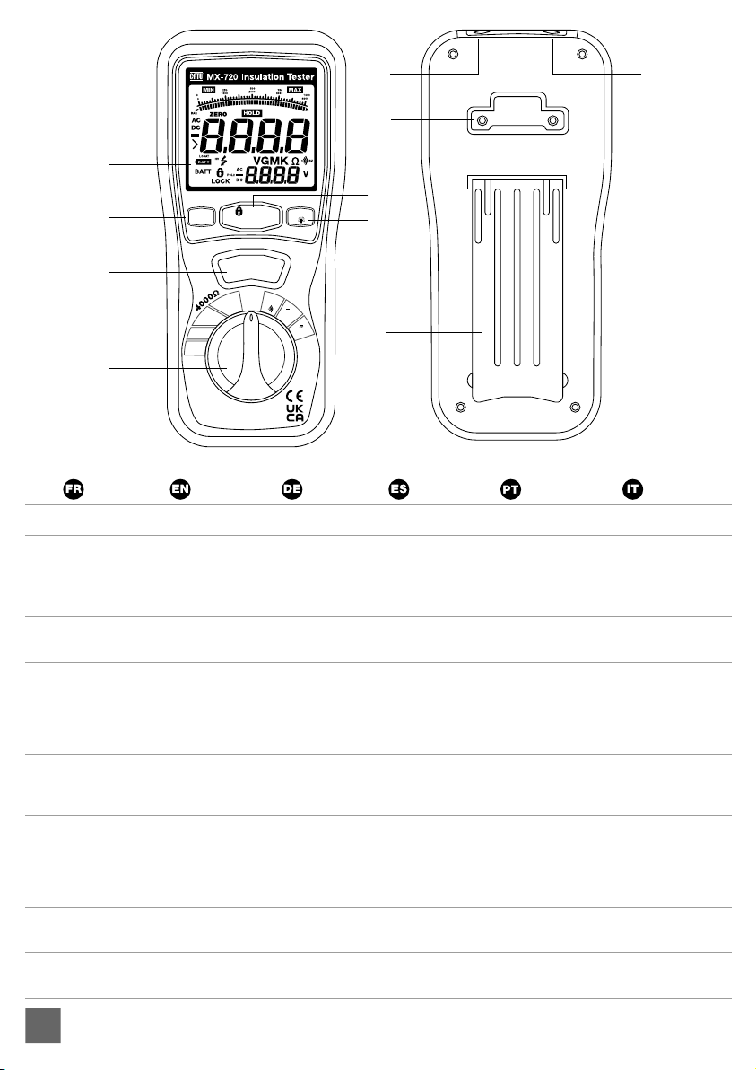
2. PARTS AND CONTROLS
2-1 HOW TO CONNECT TEST LEADS.
On MΩ Range , and 400Ω/BZ, ACV, DCV, plug the red test
lead into the “VΩ” terminal and the black lead into the “COM”
terminal.
2-2 BATTERY CHECK-UP & REPLACEMENT
a) As battery power is not sufficient, LCD will display
Replacement of 6 pcs new batteries, type 1.5V size “AA” is
required.
b) Place back the battery cover and the four screws.
2-3 TEST LEADS CHECK
Set the range select switch to the 400Ω range. With the tip and
crocodile clip of the test leads being connected, the display
should read 00.0Ω. When the leads are not connected the
display will read infinity indicated by “1”. This will ensure that
test leads are under working condition.
2-4 ROTARY SWITCH POSITIONS
Turn the tester on by selecting any measurement
Left < 1000 V, 500 V, 250 V, 125 V (4000M Ω) OFF 400Ω/BZ,
1000 V DC, 750 V AC > Right
2-5 BUTTONS AND DISPLAY INDICATORS
a) Button
• HOLD/MAX.MIN: by-pressing the “HOLD” button the 1st
time, the current values will be hold in the primary display,
but it will release in the 2nd pressing ; by pressing 2
seconds, it will enter directly into the “MAX”status, and
one another push on the button it will switch to the “MIN”,
by pressing once more, it will restart the cycle,but exit by
pressing 2 seconds again.
• LOCK: in the insulation resistance testing function ,press
the “LOCK” button, and then push down the “ TEST” key,
it will generate the high-voltage and enter the insulation
resistance testing status. Press the “TEST” button once
more, it will shut off the high-voltage and exit from the
insulation resistance testing status.
• TEST: in the insulation resistance testing function, by
pressing and holding the “TEST” button, the tester will
generate high-voltage, and enter into the insulation
resistance testing; by releasing the «TEST» button, it
will shut off the high-voltage and exit from the insulation
resistance testing.
• ZERO/LIGHT: by pressing the “ZERO/LIGHT” button the 1st
time, the current values in the primary display will be set to
zero,(mainly used for 400Ω, the low resistance testing); by
pressing a 2nd time it will return. By pressing 2 seconds,
it will enter directly into the “LIGHT” status, and the LCD
backlight lights up. After 15 seconds, the backlight shuts off
automatically, or by pressing 2 seconds within the period
of 15 s.
b) Display indications
• Primary Display: indicates the current function testing
values.
• Secondary Display: indicates the output DC voltage while
you test the insulation resistance, and the battery voltage
during the V AC test.
• Analogic Bar: indicates the current function testing value in
conjunction with the primary display.
• “ “: While testing the insulation resistance, the symbol
“ “ flashes frequently if the voltage is over 30 V.
• “•)))“: While testing the insulation resistance, the symbol
“ •)))“ flashes frequently and the buzzer warns continuously
if the output voltage is over 30V the symbol “ •)))“
is indicated while LOΩ ≤ 35Ω and the buzzer warns
continuously.
• LOCK: Push down the “LOCK” button while you test the
insulation resistance and the symbol is indicated.
• LOBAT: The display shows “LOBAT” when the voltage drops
below 7.5 V
• MAX/MIN: Stands for the maximum or the minimum.
• ZERO: Digital zero adjustment.
• HOLD: Digital holding function for the primary display.
• AC, DC: Iindicator for the voltage type.
• V, MΩ, Ω: Unit of measurement.
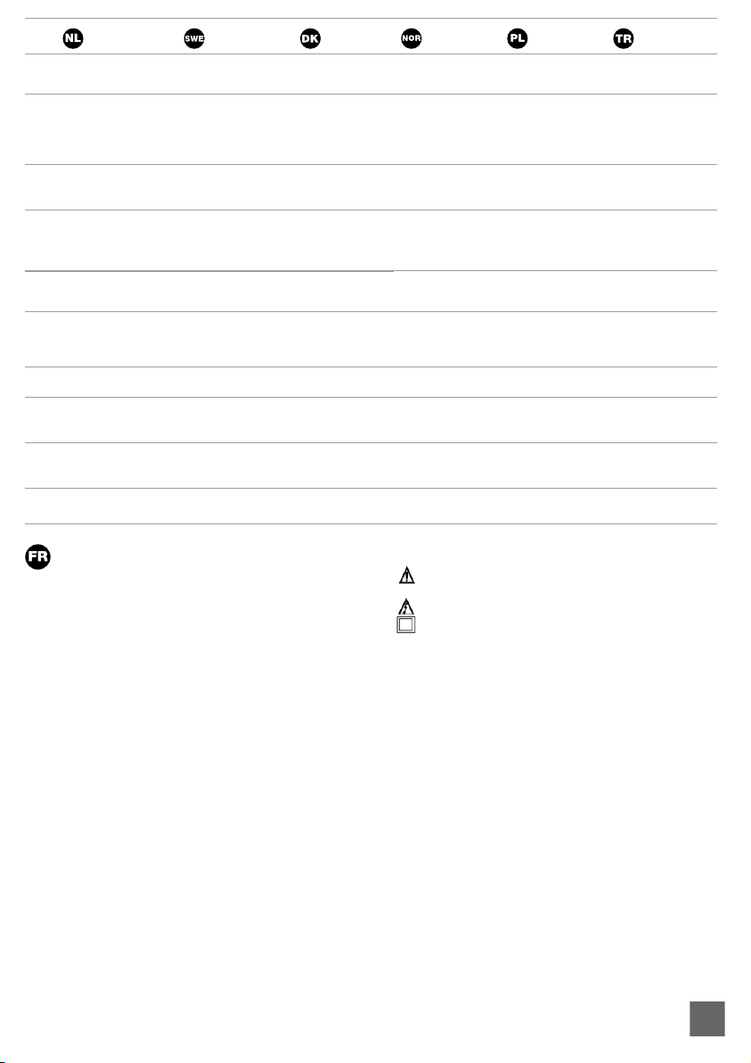
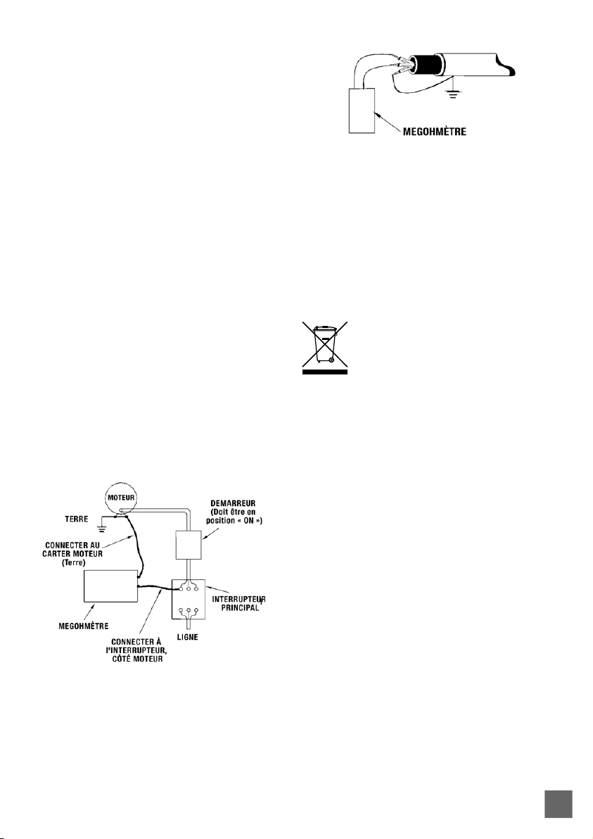
3. INSULATION RESISTANCE MEASUREMENTS
a) Turn the rotary switch from the “OFF” position to the left
(4000 MΩ/ 1 000 V---4 000/ MΩ500 V---4000 MΩ/250 V---
1000 MΩ/125 V), and chose one of the voltage-range (there
are 4 ranges namely, 4 MΩ - 40 MΩ - 400 MΩ - 4000 MΩ, can
be switched automatically for every voltage ranges).
b) Connect the two test leads to the installation to be tested;
c) Push down and hold the “TEST” button and/or press the
“ LOCK” key first and then the “TEST” button, if the tested
installation is energized and its voltage (AC/DC) is over 30
V, it will refuse to work and no high-voltage testing occurs,
simultaneously, it shows “> 30 V” on the LCD, the symbol
flashes, and the buzzer warns frequently. If the tested
installation is de-energized or its voltage is less than 30 V, it
will enter into the formal testing process and generates the
high-voltage, on the primary display, insulation resistance
in MΩ is indicated in-phase with the analogic bar; on the
secondary display, the tested insulation voltage in V (DC)
is indicated, the symbol flashes and the buzzer warns
frequently.
d) Exit the “LOCK “ status by releasing the “TEST” button or
pushing down the “LOCK” button; it will shut off the high-
voltage generation, the resistance values indicated in the
primary display will be held, and the secondary display will
still be in the status of monitoring the insulation voltage for the
tested installation.
e) Subsequently, discharge the balance insulation voltage of
the tested installation through the switch of the tester.
Turning the rotary switch can exit automatically from the
testing status during the process.

11
4. LOW RESISTANCE (CONTINUITY)
MEASUREMENTS
a) Set the range switch to the 400Ω/ BZ Position
b) Connect the red test lead to the VΩ terminal and the black
test lead to the COM terminal.
c) Connect the tips of the test leads to both ends of the circuit
under test. Read the resistance in Ω on the LCD. The two
ranges(40.00/ 400.0 Ω) can be switched automatically; the
primary display of the resistance in Ω flashes simultaneously
with the analog bar.
d) When the impedance on circuit is below approximately
≤ 35 Ω, the buzzer beeps continuously.
e) The current is between 200 and 220 mA while the tested
resistance is 0 Ω.
f)The high voltage symbol flashes along with a primary
display of “> 30 V” and the buzzer warns frequently if the
voltage (AC/ DC) is more than 30 V.
5. AC/DC VOLTAGE MEASUREMENTS
a) Set the range switch to ACV or DCV position
b) Connect the red test lead to “V Ω” terminal and the black test
lead to the terminal “COM”.
c) Connect the test point of test leads IN PARALLEL to the
circuit being measured.
d) Read the voltage value on the LCD.
6. BATTERY SAVER (SLEEP MODE)
The tester will automatically enter the “sleep mode” if there is
no function change or button press for 10 minutes. It resumes
active mode works as soon as you turn the rotary function
switch or push down any button.
7.POWER TOOLS AND SMALL APPLIANCES
This test would also apply to other similar equipment that has
power supply cables. For double-insulated power tools, the
megohmmeter wire shown connected to the housing must be
connected to a metal part of the tool (e.g. chuck or blade).
Note: The switch of the equipment must be in the “ON” position
and the main power should be disconnected.
MOTORS
AC-Disconnect the motor from the line by disconnecting the
wires at the motor terminals or by opening the main switch. If
the main switch is used and the motor also has a starter then
the starter must be held, by some means, in the “ON” position.
In the latter case, the measured resistance will include the
resistance of the motor, wire and all other components between
the motor and the main switch. If a default is indicated, the
motor and other components should be checked individually.
If the motor is disconnected at the motor terminals, connect
one megohmmeter lead to the grounded motor housing and the
other lead to one of the motor leads.
DC-Disconnect the motor from the line. To test the brush
rigging, field coils and armature connect one megohmmeter
lead to the grounded motor housing and the other lead to the
brush on the switch. If the resistance measurement indicates
a default, raise the brushes off the switch and separately test
the armature, field coils and brush rigging by connecting one
megohmmeter lead to each of them individually, leaving the
other connected to the grounded motor housing. The above
also applies to DC generators.
CABLES
Disconnect the cable from the power line. Also disconnect
the opposite end to avoid errors due to leakage from other
equipment. Check each conductor to ground and /or lead
sheath by connecting one megohmmeter lead to a ground and /
or lead sheath and the other megohmmeter lead to each of the
conductors alternatively. Check insulation resistance between
conductors by connecting the megohmmeter leads to the
conductors by pairs.
PRODUCT DISPOSAL
If you intend to dispose of this item at some point, please keep
in mind that many of its components are made of valuable
materials, which can be recycled.
Do not throw it in the trash, but check with your municipality
for recycling facilities in your area.

12
DIGITALES ISOLATIONSPRÜFGERÄT
BEDIENUNGSANLEITUNG
SICHERHEITSHINWEISE
• Lesen Sie die folgenden Sicherheitshinweise sorgfältig
durch, bevor Sie versuchen, das Messgerät zu bedienen
oder zu warten.
• Um Schäden am Gerät zu vermeiden, dürfen keine Signale
angelegt werden, die die in den Tabellen der technischen
Daten angegebenen Höchstwerte überschreiten.
• Verwenden Sie das Messgerät oder die Messleitungen
nicht, wenn sie beschädigt aussehen. Seien Sie äußerst
vorsichtig, wenn Sie in der Nähe von blanken Leitern oder
Stromschienen arbeiten.
• Versehentliches Berühren des Leiters kann zu einem
elektrischen Schlag führen.
• Verwenden Sie das Messgerät nur so, wie es in dieser
Anleitung beschrieben ist. Andernfalls kann der vom
Messgerät gebotene Schutz beeinträchtigt werden.
• Lesen Sie vor dem Gebrauch die Betriebsanleitung und
beachten Sie alle Sicherheitshinweise.
• Vorsicht beim Arbeiten mit Spannungen über 60V DC
oder 30V AC RMS. Bei solchen Spannungen besteht
Stromschlaggefahr.
• Trennen Sie vor der Durchführung von
Widerstandsmessungen oder akustischen
Durchgangsprüfungen den Stromkreis von der
Hauptstromversorgung und alle Verbraucher vom
Stromkreis.
SICHERHEITSSYMBOLE:
• Achtung: Lesen Sie dieses Handbuch, bevor Sie das
Messgerät verwenden.
• Gefährliche Spannungen.
• Das Messgerät ist durchgehend durch doppelte oder
verstärkte Isolierung geschützt.
• Verwenden Sie im Servicefall nur spezifizierte Ersatzteile.
• CE Konform mit EN-61010-1
1. SPEZIFIKATIONEN
1-1 ALLGEMEINE INFORMATIONEN
Umgebungsbedingungen:
• Installations-Kategories III
• Verschmutzungsgrad 2
• Höhenlage bis zu 2000 Meter
• Nur für den Innenbereich
• Relative Luftfeuchtigkeit 80% max.
• Betrieb Umgebungsbedingungen 0~40 ºC
Wartung & Reinigung:
• Reparaturen oder Wartungsarbeiten, die nicht in diesem
Handbuch beschrieben sind, sollten nur von qualifiziertem
Personal durchgeführt werden.
• Wischen Sie das Gehäuse regelmäßig mit einem trockenen
Tuch ab. Verwenden
Display:
• Großes LCD mit doppelter Anzeige
Messbereich:
• 4000MΩ/ 125 V, 4000MΩ/ 250V, 4000MΩ/ 500 V, 4000MΩ/
1000V, 400Ω/ BZ, 1000 V/DCV , 750V/ ACV
Abtastrate:
• 2,5 Mal pro Sekunde.
Nullabgleich:
• Automatische Einstellung.
Anzeige für Bereichsüberschreitung:
• „OL“ der höchsten Stelle wird angezeigt.
Anzeige für schwache Batterie:
• Die wird angezeigt, wenn die Batteriespannung unter
die Betriebsspannung fällt.
Betriebstemperatur:
• 0 ºC bis 40 ºC (32 ºF bis 104 ºF) und Luftfeuchtigkeit unter
80% RH
Lagertemperatur:
• -10 ºC bis 60 ºC (14 ºF bis 140 ºF) und Luftfeuchtigkeit unter
70% RH
Stromquelle:
• DC 9 V (6x1,5 V Größe „AA“ Batterie oder Äquivalent)
Maße:
• 200(L) x 92(B) x 50(H) mm
Gewicht:
• Ca. 700 g inklusive Batterien
Zubehör:
• Messleitungen, 6 Stk. Batterie, Tragetasche, Handbuch.
1-2 ELEKTRISCHE DATEN
Genauigkeiten werden in der Art und Weise angegeben, wie:
±(...% vom Messwert +...Ziffern) bei 23 ºC ±5 ºC,
unter 80% RH.

13
OHMS
Messbereich Auflösung Genauigkeit Max. offen Schaltspannung Überlastschutz
40,00 Ω 0,01 Ω +(1,2 %+3) 5,8 V 250 Vrms
40,00 Ω 0,1 Ω 5,8 V
DURCHGANGSSIGNAL
Messbereich Auflösung Betrieb Widerstand Max. offener Stromkreis Spannung Überlastschutz
•))) 0,01 Ω Widerstand ≤35Ω 5,8 V 250 Vrms
Kurzschlussstrom ≥200 mA
DC SPANNUNG
Messbereich Auflösung Genauigkeit Eingangsimpedanz Überlastschutz
1 000 V 1 V +(1,2 %+10) 10 MΩ 1 000 Vrms
WECHSELSPANNUNG (40HZ ~ 400HZ)
Messbereich Auflösung Genauigkeit Eingangsimpedanz Überlastschutz
750 V 1 V +(1,2 %+10) 10 MΩ 750 Vrms
MEG OHMS
Anschluss- oder
Klemmenspannung Messbereich
(MΩ) Auflösung (MΩ) Genauigkeit Prüfstrom Kurzschluss
strom
125 V
(0 %~+10 %)
0,125~4 000 0,001 +(2 %+10)
1mA @ Last
125kΩ ≤1 mA
4 001~40,00 0,01 +(2 %+10)
40,01~400,0 0,1 +(4 %+5)
400,1~4 000 1 +(5 %+5)
250 V
(0 %~+10 %)
0,250~4 000 0,001 +(2 %+10)
1mA @ Last
250kΩ ≤1 mA
4 001~40,00 0,01 +(2 %+10)
40,01~400,0 0,1 +(3 %+5)
400,1~4 000 1 +(4 %+5)
500 V
(0 %~+10 %)
0,500~4 000 0,001 +(2 %+10)
1 mA
@Last 500 kΩ ≤1 mA
4 001~40,00 0,01 +(2 %+10)
40,01~400,0 0,1 +(2 %+5)
400,1~4 000 1 +(4 %+5)
1 000 V
(0 %~+10 %)
1 000~4 000 0,001 +(3 %+10)
1 mA
@Last 1 MΩ ≤1 mA
4 001~40,00 0,01 +(2 %+10)
40,01~400,0 0,1 +(2 %+5)
400,1~4 000 1 +(4 %+5)

14
2. TEILE & BEDIENELEMENTE
2-1 SO SCHLIESSEN SIE DIE MESSLEITUNGEN AN
Im MΩ-Bereich und 400Ω/ BZ, ACV, DCV, Schließen Sie die rote
Messleitung an die Klemme „VΩ“ und die schwarze Leitung an
die Klemme „COM“ an.
2-2 ÜBERPRÜFUNG UND AUSTAUSCH DER BATTERIEN
a) Da die Batterieleistung nicht ausreichend ist, auf dem
LCD wird angezeigt Der Austausch von 6 Stück neuen
Batterien, Typ 1,5V Größe „AA“ ist erforderlich.
b) Setzen Sie die Batterieabdeckung wieder auf und drehen Sie
die vier Schrauben fest.
2-3 MESSLEITUNGEN PRÜFEN
Stellen Sie den Bereichswahlschalter auf den 400-Ω-Bereich
mit angeschlossener Spitze und Krokodilklemme der
Messleitungen. Die Anzeige sollte 00,0Ω anzeigen.
Wenn die Leitungen nicht angeschlossen sind, zeigt
das Display unendlich an, angezeigt durch eine „1“.
Dadurch wird sichergestellt, dass die Messleitungen unter
Betriebsbedingungen sind.
2-4 DREHSCHALTERPOSITIONEN
Schalten Sie den Tester ein, indem Sie eine beliebige Messung
auswählen
Steigerung < 1 000 v, 500 v, 250 v, 125 v (4 000MΩ) AUS
400Ω/BZ, 1 000 V DC, 750 V AC > Rechts
2-5 TASTEN UND DISPLAY ANZEIGEN
a) Taste
• HALTEN/MAX.MIN: Bei der ersten Betätigung der „HOLD“-
Taste werden die aktuellen Werte in der Primäranzeige
gehalten, aber bei der zweiten Betätigung kehren sie zurück;
bei einer Betätigung von 2 Sekunden gehen sie direkt in den
„MAX“-Status über, und bei einer weiteren Betätigung gehen
sie in den „MIN“-Status über; bei einer weiteren Betätigung
werden sie wiederhergestellt, aber bei einer weiteren
Betätigung von 2 Sekunden verlassen.
• LOCK: In der Isolationswiderstands-Testfunktion drucken
Sie die Taste „LOCK“, dann drücken Sie kontinuierlich
die Taste „TEST“, die Hochspannung wird erzeugt
und die Isolationswiderstands-Prüfung wird gestartet.
Drucken Sie noch einmal die Taste „TEST“, um die
Hochspannung abzuschalten und den Zustand der
Isolationswiderstandprüfung zu verlassen.
• TEST: Bei der Isolationswiderstandsprüfung wird
durch Drücken und Halten der Taste „TEST“ das
Messgerät Hochspannung erzeugen und in die
Isolationswiderstandsprüfung eintreten; wird die Taste „TEST“
nicht gedrückt, wird die Hochspannung abgeschaltet und die
Isolationswiderstandsprüfung beendet.
• ZERO/LIGHT: Wenn Sie die „ZERO/LIGHT“-Taste zum ersten
Mal drücken, werden die aktuellen Werte in der
Primäranzeige auf Null gesetzt (hauptsächlich für 400Ω, die
Prüfung von niedrigen Widerständen), und sie kehrt zurück,
wenn Sie sie zum zweiten Mal drücken. Wenn Sie die Taste 2
Sekunden lang drücken, geht sie direkt in den „LIGHT“-Status
über, und die LCD-Hintergrundbeleuchtung leuchtet auf. Nach
15 Sekunden wird die Hintergrundbeleuchtung automatisch
ausgeschaltet, genauso wie bei 2 Sekunden langem Drücken
innerhalb von 15s.
b) Display-Anzeigen
• Die Primäranzeige: Zeigt die aktuellen Funktionstestwerte
• Die sekundäre Anzeige: Sie zeigt die Ausgangs-DCV an,
während Sie den Isolationswiderstand testen, und die
Batteriespannung, während die ACV
• Der Analogbalken: zeigt den aktuellen Funktionstestwert
synchron zur Primäranzeige an.
• : Während der Prüfung des Isolationswiderstands blinkt
das Symbol häufig, wenn die Spannung über 30 V liegt.
• •))): Bei der Prüfung des Isolationswiderstandes wird das
Symbol „•)))“ häufig und der Summer warnt ständig, wenn
die Außenspannung über 30V liegt, das Symbol „ •)))“ wird
angezeigt, während LOΩ ≤35Ω und die BZ kontinuierlich
warnt.
• LOCK: Drücken Sie die Taste „LOCK“, während Sie den
Isolationswiderstand prüfen und das Symbol wird
angezeigt.
• LOBAT: Das Display zeigt „LOBAT“ an, wenn die Spannung
unter 7,5V fällt
• MAX/MIN: Stand für das Maximum oder das Minimum.
• NULL: Digitaler Nullabgleich.
• HOLD: Die digitale Haltefunktion für die Primäranzeige.
• AC, DC: Die Anzeige für die Spannungseigenschaft.
• V, MΩ, Ω: Die gemessenen Maßeinheiten.
3. ISOLATIONSWIDERSTANDSMESSUNGEN
a) Drehen Sie den Funktionsschalter aus der Position „OFF“
nach links(4 000 MΩ/1 000 V---4 000/ MΩ 500 V---
4 000 MΩ/250 V---1 000 MΩ/125 V) und wählen Sie einen der
Spannungsblöcke (es gibt 4 Bereiche, nämlich 4 MΩ - 40 MΩ -
400 MΩ - 4000 MΩ, die automatisch für jeden Spannungsblock
umgeschaltet werden können).
b)Verbinden Sie zwei Prüfleitungen mit dem geprüften;
c) Halten Sie die Taste „TEST“ gedrückt oder drücken Sie
zuerst die Taste „LOCK“ und dann die Taste „TEST“. Wenn
das zu prüfende Gerät stromführend ist und seine Spannung
(AC/DC) über 30 V liegt, verweigert es die Arbeit und es
erfolgt keine Hochspannungsprüfung, gleichzeitig wird „>
30 V“ auf dem LCD angezeigt, das Symbol „ “ blinkt und
der Summer warnt häufig. Wenn das zu prüfende Gerät
nicht elektrisch leitfähig ist oder seine Spannung unter 30
V liegt, geht es in den formalen Prüfprozess über und führt
die Hochspannungsprüfung durch. Auf der primären Anzeige
wird der Isolationswiderstand in MΩ phasengleich mit dem
Analogbalken angezeigt; auf der sekundären Anzeige wird die
geprüfte Isolationsspannung in V (DC) angezeigt, das Symbol „
“ blinkt und der Summer warnt häufig
d) Frei von der „TEST“-Taste oder Drücken der „TEST“-
Taste in der „LOCK “ Status kann aus dem „LOCK“-
Status und Abschalten der Hochspannung, synchron, die
Widerstandswerte in der primären Anzeige angezeigt wird
gehalten werden, und die sekundäre Anzeige noch in den
Status der Überwachung der Isolationsspannung für die
getestet werden.

15
e) Entladen Sie anschließend die Ausgleichsisolationsspannung
des Geprüften über den inneren Schalter des Messgeräts.
Durch Drehen des Funktionsschalters kann der Teststatus
während des Prozesses automatisch verlassen werden.
4. NIEDEROHMIGE (DURCHGANGS-)MESSUNGEN
a). Stellen Sie den Bereichsschalter auf 400Ω/BZ Position
b). Schließen Sie die rote Messleitung an die Klemme V Ω und
die schwarze an die Klemme COM an.
c). Schließen Sie die Spitzen der Messleitungen an beide Enden
des zu prüfenden Stromkreises an. Lesen Sie den Widerstand in
Ω auf der LCD-Anzeige ab. Die beiden Bereiche (40,00/400,0Ω)
können automatisch umgeschaltet werden; die primäre Anzeige
des Widerstandes in Ω, blinkt synchron mit dem Analogbalken.
d). Wenn die Impedanz im Stromkreis unter etwa ≤ 35Ω. Es wird
durch einen Dauerton angezeigt.
e) Der Strom liegt zwischen 200 und 220mA, während der
geprüfte Widerstand 0Ω
f) Das Hochspannungssymbol
blinkt zusammen mit einer primären Anzeige von > 30 V“
und der Summer warnt häufig, wenn die Spannung (AC/DC)
mehr als 30 V beträgt.
5. AC/DC-SPANNUNGSMESSUNGEN
a) Stellen Sie den Bereichsschalter auf die Position ACV oder
DCV
b). Rote Messleitung an Klemme „V Ω“ und schwarze
Messleitung an Klemme „COM“ anschließen.
c) Schließen Sie die Prüfspitzen der Messleitungen IN
PARALLEL an den zu messenden Stromkreis an.
d) Lesen Sie den Spannungswert auf dem LCD ab.
6. BATTERIESCHONER (SCHLAFMODUS)
Das Messgerät geht automatisch in den „Schlafmodus“,
wenn 10 Minuten lang keine Funktionsänderung oder kein
Tastendruck erfolgt, aber es funktioniert, sobald Sie den
Funktionsdrehschalter drehen oder eine Taste drücken.
7. ELEKTROWERKZEUGE UND KLEINGERÄTE
Dieser Test würde auch für andere ähnliche Geräte gelten,
die über ein Netzkabel verfügen. Bei doppelt isolierten
Elektrowerkzeugen wird die gezeigte, mit dem Gehäuse
verbundene Megohmmeterleitung mit einem Metallteil des
Werkzeugs (z. B. Spannfutter, Klinge) verbunden.
Hinweis: Der Schalter des Geräts muss in der Position „ON“
stehen und die Hauptstromversorgung sollte unterbrochen
sein.
MOTOREN
AC - Trennen Sie den Motor vom Netz, indem Sie die Drähte an
den Motorklemmen abklemmen oder den Hauptschalter öffnen.
Wenn der Hauptschalter verwendet wird und der Motor auch
einen Anlasser hat, muss der Anlasser auf irgendeine Weise in
der Position „ON“ gehalten werden. Im letzteren Fall umfasst der
gemessene Widerstand den Widerstand des Motors, des Kabels
und aller anderen Komponenten zwischen dem Motor und dem
Hauptschalter. Wenn eine Schwäche festgestellt wird, sollten der
Motor und andere Komponenten einzeln überprüft werden. Wenn
der Motor an den Motorklemmen abgeklemmt ist, schließen Sie
eine Leitung des Megohmmeters an das geerdete Motorgehäuse
und die andere Leitung an eine der Motorleitungen an. DC
- Trennen Sie den Motor von der Leitung. Zum Testen der
Bürstenbestückung, der Feldspulen und des Ankers schließen
Sie ein Megohmmeter-Kabel an das geerdete Motorgehäuse
und das andere Kabel an die Bürste am Schalter an. Wenn die
Widerstandsmessung eine Schwäche anzeigt, heben Sie die
Bürsten vom Kommutator ab und prüfen Sie Anker, Feldspulen
und Bürstenaufhängung separat, indem Sie ein Megohmmeter-
Kabel an jedes einzelne anschließen und das andere mit dem
geerdeten Motorgehäuse verbunden lassen. Das oben Gesagte
gilt auch für DC-Generatoren.
KABEL
Trennen Sie das Kabel von der Leitung. Trennen Sie auch das
gegenüberliegende Ende, um Fehler durch Leckagen von anderen
Geräten zu vermeiden. Prüfen Sie jeden Leiter auf Erdung und/
oder Leitungsmantel, indem Sie eine Megohmmeterleitung an
eine Erdung und/oder einen Leitungsmantel und die andere
Megohmmeterleitung nacheinander an jeden der Leiter
anschließen. Prüfen Sie den Isolationswiderstand zwischen den
Leitern, indem Sie die Leitungen des Megohmmeters paarweise
an die Leiter anschließen.
PRODUKTENTSORGUNG
Wenn Sie diesen Artikel irgendwann entsorgen möchten,
denken Sie bitte daran, dass viele seiner Bestandteile aus
wertvollen Materialien bestehen, die recycelt werden können.
Werfen Sie es nicht in den Müll, sondern erkundigen Sie sich
bei Ihrer Gemeinde nach Recyclingmöglichkeiten in Ihrer Nähe.

16
MEDIDOR DIGITAL DE AISLAMIENTO
MANUAL DE INSTRUCCIONES
INSTRUCCIONES DE SEGURIDAD
• Lea atentamente las instrucionnes de seguridad siguientes
antes de intentar utilizar o realizar el mantenimiento del
medidor.
• No aplique las señales que superen los límites máximos
mostrados en las tablas de especificaciones técnicas para
evitar daños en el instrumento.
• No utilice el medidor ni los cables de medición si parecieran
dañados. Tenga mucho cuidado cuando esté cerca de
conductores o barras colectoras desnudas.
• El contacto accidental con el conductor podría provocar una
descarga eléctrica.
• Utilice el medidor únicamente según se menciona en este
manual. De lo contrario, la protección proporcionada por el
medidor podría verse afectada.
• Lea las instrucciones de funcionamiento antes de usar el
aparato y siga todas las instrucinnes de seguridad.
• Tenga precaución cuando trabaje con tensiones superiores
a 60 V CC o 30 V CA RMS. Estos voltajes implican riesgo de
descarga.
• Antes de tomar mediciones de la resistencia o probar la
continuidad acústica, desconecte el circuito del suministro
eléctrico y todas las cargas del circuito.
SÍMBOLOS DE SEGURIDAD:
• Precaución, consulte el manual antes de utilizar el
medidor.
• Voltajes peligrosos.
• El medidor está protegido mediante doble aislamiento o
aislamiento reforzado.
• Cuando repare el aparato, utilice únicamente las piezas de
repuesto especificadas.
• Conformidad CE con la norma EN-61010-1.
1. ESPECIFICACIONES
1-1 INFORMACIÓN GENERAL
Condiciones ambientales:
• Categorías de instalación III
• Grado de contaminación 2
• Altitud hasta 2000 metros
• Solo para uso en interiores
• Humedad relativa 80% máx.
• Temperatura ambiental de funcionamiento 0~40 ºC
MANTENIMIENTO Y LIMPIEZA:
• Únicamente personal cualificado debe realizar las
reparaciones o mantenimiento no cubiertos en este manual.
• Limpie la carcasa regularmente con un paño seco. No utilice
disolventes ni productos abrasivos en estos instrumentos.
Pantalla:
LCD grande con pantalla doble
Rango de medición:
4 000 MΩ/125 V, 4 000 MΩ/250 V, 4 000 MΩ/500 V, 4 000
MΩ/1 000 V, 400 Ω/BZ, 1 000 V/DC V. 750 V CA
Frecuencia de muestreo:
2,5 veces por segundo.
Ajuste cero:
Ajuste automático.
Indicador fuera de rango:
“OL” de mayor dígito mostrado.
Indicador de batería baja:
Aparece cuando la tensión de la batería cae por debajo de
la tensión de funcionamiento.
Temperatura de funcionamiento:
0 ºC a 40 ºC (32 ºF a 104 ºF) y humedad por debajo de 80% HR
Temperatura de almacenamiento:
-10 ºC a 60 ºC (14 ºF a 140 ºF) y humedad por debajo de 70%
HR
Fuente de alimentación:
9 V CC (6 x pilas tamaño “AA” de 1,5 V o equivalente)
Dimensiones:
200 (La.) x 92 (An.) x 50 (Al.) mm
Peso:
Aproximadamente 700 g (pilas incluidas)
Accesorios: Cables de prueba, 6 pilas, funda de transporte,
manual.
Accesorios:
Cables de prueba, 6 pilas, funda de transporte, manual.
1-2 ESPECIFICACIONES ELÉCTRICAS
Las precisiones se especifican del modo siguiente:
± (…% de lectura +…dígitos) a 23 ºC ± 5 ºC, por debajo de
80% HR

17
OHMIOS
Rango Resolución Precisión Apertura máx. tensión del circuito Sobrecarga Protección
40,00 Ω 0,01 Ω +(1,2 %+3) 5,8 V 250 Vrms
40,00 Ω 0,1 Ω 5,8 V
ALERTA DE CONTINUIDAD
Rango Resolución Funcionamiento
Resistencia Circuito abierto máx. Voltaje Sobrecarga Protección
•))) 0,01 Ω Resistencia ≤35Ω 5,8 V 250 Vrms
Corriente de cortocircuito ≥200 mA
TENSIÓN CC
Rango Resolución Precisión Impedancia de entrada Sobrecarga Protección
1 000 V 1 V +(1,2 %+10) 10 MΩ 1 000 Vrms
TENSIÓN CA (40HZ ~ 400HZ)
Rango Resolución Precisión Impedancia de entrada Sobrecarga Protección
750 V 1 V +(1,2 %+10) 10 MΩ 750 Vrms
OHMIOS MEG
Tensión de terminal Rango (MΩ) Resolución (MΩ) Precisión Corriente de
prueba Corriente de
cortocircuito
125 V
(0 %~+10 %)
0,125~4 000 0,001 +(2 %+10)
1 mA
@load 125 kΩ ≤1 mA
4 001~40,00 0,01 +(2 %+10)
40,01~400,0 0,1 +(4 %+5)
400,1~4 000 1 +(5 %+5)
250 V
(0 %~+10 %)
0,250~4 000 0,001 +(2 %+10)
1 mA
@load 250 kΩ ≤1 mA
4 001~40,00 0,01 +(2 %+10)
40,01~400,0 0,1 +(3 %+5)
400,1~4 000 1 +(4 %+5)
500 V
(0 %~+10 %)
0,500~4 000 0,001 +(2 %+10)
1 mA
@load 500 kΩ ≤1 mA
4 001~40,00 0,01 +(2 %+10)
40,01~400,0 0,1 +(2 %+5)
400,1~4 000 1 +(4 %+5)
1 000 V
(0 %~+10 %)
1 000~4 000 0,001 +(3 %+10)
1 mA
@load 1 MΩ ≤1 mA
4 001~40,00 0,01 +(2 %+10)
40,01~400,0 0,1 +(2 %+5)
400,1~4 000 1 +(4 %+5)

18
2. PIEZAS Y CONTROLES
2-1 CÓMO CONECTAR LOS CABLES DE PRUEBA
En Rango MΩ, y 400 Ω/BZ, ACV,.DCV, conecte el cable de
prueba rojo en el terminal “VΩ” y el cable negro en el terminal
“COM”.
2-2 COMPROBACIÓN Y SUSTITUCIÓN DE LAS PILAS
a) La carga de las pilas no es suficiente. El LCD mostrará.
Sustitúyalas por 6 pilas nuevas de tamaño “AA” y 1,5 V.
b) Coloque la tapa de las pilas y los cuatro tornillos.
2-3 COMPROBACIÓN DE LOS CABLES DE PRUEBA
Establezca el interruptor de selección de rango en el rango 400
Ω. con la punta y la pinza de los cables de prueba conectadas.
El indicador debe mostrar 00,0 Ω. Cuando los cables no están
conectados la pantalla mostrará infinito indicado por “1”. Esto
garantizará que el cable de prueba funciona correctamente.
2-4 POSICIONES DEL INTERRUPTOR GIRATORIO
Gire el medidor seleccionando cualquier medición
Izquierda < 1000 v, 500 v, 250 v, 125 v (4000 MΩ)
APAGADO 400 Ω/BZ, 1000 V CC, 750 V CA > Derecha
2-5 BOTONES E INDICADORES DE LA PANTALLA
a) Botón
• MANTENER/MÁX.MÍN: Al presionar brevemente el botón
“MANTENER” por primera vez, los valores actuales
se mantendrán en la pantalla principal pero volverán
al pulsar por 2.ª vez. Si presiona durante 2 segundos,
entrará directamente en el estado “MÁX”, y si presiona
brevemente una vez más cambiará a “MÍN”. Si presiona
instantáneamente una vez más, empezará desde el principio,
pero saldrá si mantiene pulsado durante 2 segundos
nuevamente.
• BLOQUEO: En la función de prueba de resistencia de
aislamiento, presione el botón “BLOQUEO” y luego presione
la tecla “PRUEBA”, se aplicará alta tensión y entrará en el
estado de prueba de resistencia de aislamiento. Presione el
botón “PRUEBA” una vez más, se desactivará la alta tensión
y saldrá del estado de prueba de resistencia de aislamiento.
• PRUEBA: En la función de prueba de resistencia de
aislamiento, manteniendo presionado el botón “PRUEBA”,
el medidor aplicará en alta tensión y entrará en la prueba de
resistencia de aislamiento, terminando la prueba, cortará
la alta tensión y saldrá de la prueba de resistencia de
aislamiento.
• CERO/LUZ: Si presiona brevemente el botón “CERO/LUZ”
por primera vez, los valores actuales de la pantalla principal
se establecerán en cero (se utiliza principalmente para 400
Ω, la prueba de baja resistencia), volverá si está
en el 2.ª vez. Si lo presiona durante 2 segundos, entrará
directamente en el estado de “LUZ” y la luz de fondo de la
pantalla LCD se encenderá.
Después de 15 segundos,
se apaga la luz de fondo y también lo hará si pulsa durante 2
segundos en menos de 15 s.
b) Indicadores de pantalla
• Pantalla principal: Indica los valores de prueba de la función
actual
• Pantalla secundaria: Muestra la salida V CC durante la
prueba de resistencia del aislamiento y la tensión de batería
en V CA.
• Barra analógica: indica el valor de prueba de la función de
corriente en sincronía con la pantalla principal.
• : durante la prueba de resistenca del aislamiento, el
símbolo parpadea frecuentemente si la tensión es
superior a 30 V.
• •))): Durante la prueba de resistencia del aislamiento, el
símbolo “•)))” parpadea frecuentemente y el timbre advierte
continuamente si la tensión exterior es superior a 30 V. El
símbolo “•)))” se indica mientras LOΩ≤35Ω y BZ advierten
continuamente.
• BLOQUEO: Pulse el botón “BLOQUEO” mientras prueba la
resistencia del aislamiento y se indique el símbolo “ ”.
• LOBAT: La pantalla muestra “LOBAT” si la tensión cae por
debajo de 7,5 V.
• MÁX/MÍN significan máximo y mínimo.
• CERO: Ajuste de cero digital.
• MANTENER: Función de retención digital de la pantalla
principal.
• CA, CC: Indicador del tipo de tensión.
• V, MΩ, Ω: Unidades de medición.
3. MEDICIONES DE RESISTENCIA DEL
AISLAMIENTO
a) Gire el selector de función desde la posición “APAGADO”
hacia la izquierda (4 000 MΩ/ 1 000 V---4 000/MΩ500 V---4
000 MΩ/250 V---1 000 MΩ/125 V), y elija uno de los bloques
de tensión (hay 4 rangos, a saber, 4 MΩ40 MΩ400 MΩ4000
MΩ,que se pueden cambiar automáticamente para cada bloque
de tensión).
b) Conecte los dos cables de prueba a probar;
c) Mantenga presionado el botón “PRUEBA”/o presione
el botón “BLOQUEO” para tomar primero y luego el botón
“PRUEBA”, si la prueba es electrífera y su tensión (CA/CC) es
superior a 30 V, rechazará el trabajo y no habrá ninguna prueba
de alta tensión. Simultáneamente, muestra “> 30 V” en la
pantalla LCD, el símbolo
parpadea y el timbre advierte frecuentemente. Si la prueba
es deselectrífera o su tensión es inferior a 30 V, entrará en el
proceso de prueba formal y aplicará alta tensión. En la pantalla
principal, la resistencia de aislamiento en MΩ se indica en fase
con una barra analógica; en la pantalla secundaria, se indica
la tensión de aislamiento probada en V (CC), el símbolo
parpadea y el timbre advierte frecuentemente.
d) Si libera el botón “PRUEBA” o presiona el botón “PRUEBA”
en el estado “BLOQUEO”, puede salir del estado “BLOQUEO”
y apagar la alta tensión, sincrónicamente, los valores de
resistencia que aparecen en la pantalla principal se mantendrá,
y la pantalla secundaria todavía estará en el estado de
monitoreo de la tensión de aislamiento de la prueba.
e) Posteriormente, descargue la tensión de aislamiento de
equilibrio de la prueba a través del interruptor interno del
medidor.
Al girar el interruptor de función se puede salir
automáticamente del estado de prueba durante el proceso.

19
4. MEDICIONES DE BAJA RESISTENCIA
(CONTINUIDAD)
a) Coloque el interruptor de rango en la posición 400 Ω/BZ.
b). Conecte el cable de prueba rojo al terminal V Ω y el negro
al terminal COM.
c) Conecte las puntas de los cables de prueba a ambos
extremos del circuito bajo prueba. Lea la resistencia en
Ω en la pantalla LCD. Los dos rangos (40,00/400,0Ω) se
pueden cambiar automáticamente; la pantalla principal de la
resistencia en Ω, parpadea en sincronía con la barra analógica.
d) Cuando la impedancia del circuito está por debajo de
aproximadamente Description ≤35 Ω, se indicará mediante un
pitido continuo.
e) La corriente es de 200 a 220mA mientras que la resistencia
probada es 0Ω
f) El símbolo de alta tensión parpadea junto con la
indicación de > 30 V de la pantalla principal y el timbre
advierte frecuentemente si la tensión (CA/CC) es superior a
30 V.
5. MEDICIONES DE TENSIÓN CA/CC
a) Coloque el interruptor de rango en la posición ACV o DCV.
b) Conecte el cable de prueba rojo al terminal “V Ω” y el negro
al terminal “COM”.
c) Conecte las clavijas de prueba de los cables de prueba EN
PARALELO al circuito que está probando.
d) Lea el valor de tensión del LCD.
6. AHORRO DE BATERÍA (MODO DE SUSPENSIÓN)
El medidor entrará automáticamente en “modo de suspensión”
si no hay cambio de función o si no se presiona ningún botón
durante 10 minutos, pero empezará a funcionar en cuanto se
gire el interruptor giratorio de función o se presione cualquier
botón.
7. HERRAMIENTAS ELÉCTRICAS Y PEQUEÑOS
ELECTRODOMÉSTICOS
Esta prueba también se aplicaría a otros equipos similares
que tengan un cable de línea. Para herramientas eléctricas
con doble aislamiento, el cable del megóhmetro que se
muestra conectado a la carcasa estaría conectado a alguna
parte metálica de la herramienta (por ejemplo, portabrocas,
cuchilla).
Nota: El interruptor del dispositivo debe estar en la posición
“ENCENDIDO” y la alimentación principal debe estar
desconectada.
MOTORES
Desconecte la corriente CA del motor de la línea
desconectando los cables en los terminales del motor o
abriendo el interruptor principal. Si se utiliza el interruptor
principal y el motor también tiene un motor de arranque,
se debe mantener, de alguna manera, en la posición
“ENCENDIDO”. En el segundo caso, la resistencia medida
incluirá la resistencia del motor, el cable y todos los demás
componentes entre el motor y el interruptor principal. Si se
indica una debilidad, se debe revisar individualmente el motor
y otros componentes. Si el motor está desconectado de los
terminales del motor, conecte un cable del megaóhmetro a la
carcasa del motor con conexión a tierra y el otro cable a uno
de los cables del motor. Desconecte la corriente CC de la línea.
Para probar el aparejo de la escobilla, las bobinas de campo
y el inducido, conecte un cable del megaóhmetro a la carcasa
del motor con conexión a tierra y el otro cable a la escobilla
del conmutador. Si la medición de la resistencia indica una
debilidad, levante las escobillas del conmutador y pruebe por
separado el inducido, las bobinas de campo y el aparejo de
las escobillas conectando un cable del megóhmetro a cada
uno de ellos individualmente, dejando el otro conectado a la
carcasa del motor con conexión a tierra. Lo anterior también
es aplicable a los generadores CC
CABLES
Desconecte el cable de la línea. Desconecte también el
extremo opuesto para evitar errores por fuga del otro equipo.
Compruebe cada conductor a tierra y/o cubierta de cable
conectando un cable del megaóhmetro a un cable de tierra y/o
cubierta de cable y el otro cable del megaóhmetro a cada uno
de los conductores por turnos. Compruebe la resistencia del
aislamiento entre los conductores conectando los cables del
megóhmetro a los conductores por parejas.
ELIMINACIÓN DE PRODUCTO
Si tiene la intención de deshacerse de este artículo en algún
momento, tenga en cuenta que muchos de sus componentes
están hechos de materiales valiosos que pueden reciclarse.
No lo arroje a la basura, pero consulte con su municipio sobre
las instalaciones de reciclaje en su área.

20
EQUIPAMENTO DE TESTE DIGITAL DE
ISOLAMENTO MANUAL DE INSTRUÇÕES
INFORMAÇÕES DE SEGURANÇA
• Leia atentamente as seguintes informações de segurança
antes de tentar operar ou reparar o aparelho.
• Para evitar provocar danos no instrumento, não aplique
os sinais que excedam os limites máximos indicados nas
tabelas de especificações técnicas.
• Não utilize o aparelho nem os cabos de teste se
apresentarem danos. Tenha extremo cuidado quando
trabalhar junto de conductores descobertos ou barras de
terminais.
• O contacto acidental com o condutor pode resultar em
choque elétrico.
• Utilize o aparelho apenas como especificado neste manual.
Caso contrário, a protecção fornecida pelo medidor pode
ser prejudicada.
• Leia as instruções de funcionamento antes de utilizar e siga
todas as informações de segurança.
• Tenha o devido cuidado ao trabalhar com tensões
superiores a 60V DC ou 30V AC RMS. Estas tensões
apresentam um risco de choque.
• Antes de efetuar medições de resistência ou testar a
continuidade acústica, desligue o circuito da fonte de
alimentação principal e todas as cargas do circuito.
SÍMBOLOS DE SEGURANÇA:
• Cuidado: consulte este manual antes de utilizar o
medidor.
• Tensões perigosas.
• O medidor é protegido em toda a sua extensão por
duplo isolamento ou isolamento reforçado.
• Quando efetuar reparações, utilize apenas as peças de
substituição especificadas.
• CE Em conformidade com a norma EN-61010-1
1. ESPECIFICAÇÕES
1-1 INFORMAÇÕES GERAIS
Condições ambientais:
• Categorias de instalação III
• Nível 2 de poluição
• Altitude até 2.000 metros
• Utilização apenas em espaços interiores
• Humidade relativa máxima de 80%.
• Temperatura ambiente de funcionamento 0~40ºC
MANUTENÇÃO E LIMPEZA:
• As reparações ou serviços de assistência não cobertos
por este manual só devem ser efetuados por pessoal
qualificado.
• Limpe periodicamente a estrutura com um pano seco. Não
utilize abrasivos ou solventes nestes instrumentos. .
Ecrã:
LCD grande com visor duplo.
Amplitude de medição:
4 000 MΩ/125 V, 4 000 MΩ/250 V, 4 000 MΩ/500 V, 4 000
MΩ/1 000 V, 400 Ω/BZ, 1 000 V/DC V. 750 V CA
Taxa de Amostragem:
2,5 vezes por segundo.
Ajuste para zero:
Ajuste automático.
Indicador de Excesso de Alcance:
É exibido “OL” do dígito mais alto.
Indicação de bateria fraca:
O sinal é exibido quando a tensão da bateria desce além
da tensão de funcionamento.
Temperatura de funcionamento:
0ºC a 40ºC (32ºF a 104ºF) e Humidade inferior a 80% RH
Temperatura de armazenamento:
-10ºC a 60ºC (14ºF a 140ºF) e Humidade inferior a 70% RH
Fonte de alimentação:
DC9V (6 pilhas “AA” de 1,5V ou equivalente)
Dimensões:
200(C) x 92(L) x 50(A) mm
Peso:
Aprox 700g, incluindo as pilhas
Acessórios:
Cabos de teste, 6 pilhas, estojo de transporte, manual.
1-2 ESPECIFICAÇÕES ELÉTRICAS
As precisões são especificadas da seguinte forma:
±(…% de leitura +…dígitos) a 23ºC±5ºC, inferior a 80% RH.
Table of contents
Languages: