Elcontrol VIP CLAMP MINI Series User manual
V
V
I
I
P
P
C
C
L
L
A
A
M
M
P
P
M
M
I
I
N
N
I
I
PRECAUTIONS FOR USE
Never use on networks with voltage higher than 600 V
in relation to the ground and whose overvoltage category
is higher than III, i.e. fixed industrial and domestic
installations see IEC 664-1).
Indoor use in environments with a degree of pollution
of 2 maximum cf. IEC 664-1), temperature of 0°C to +
50°C and relative humidity lower than 70%.
Use accessories compliant with safety standards
NF EN 61010-2-031) with minimal voltage of 600 V
and overvoltage category III.
Never open the clamp box before disconnecting all
power sources.
Never connect to the circuit to be measured if the clamp
box is not properly closed.
Before any measurement, check the proper positioning
of the cables and switch.
When measuring current check for proper alignement
of the conductor in relation to the markers and proper
closing of the jaws.
Always disconnect the clamp from any power source
before changing the battery.
Do not perform resistance tests, continuity tests or semi-
conductor tests on a circuit under power.
USER MANUAL
Thank you for purchasing this VIP CLAMP
MINI series multimeter clamp.
To get the best service from this instrument:
_ read this users manual carefully,
_ respect the safety precautions detailed
Via Vizzano,44 - 40037 Pontecchio Marconi (Bologna) Italy
Tel.+3 0516782006 Fax +3 051845544
......................................................................................
http://www.elcontrol-energy.net
e-mail (Comm.le Italia) vendite@elcontrol-energy.net
e-mail (Sales Dept.) sales@elcontrol-energy.net
English

V
V
I
I
P
P
C
C
L
L
A
A
M
M
P
P
M
M
I
I
N
N
I
I
SOMMARIO
.PRESENTATION... .............................................................................................................1
2. DESCRIPTION ..................................................................................................................1
3. IMLEMENTATION-FUNCTIONAL CHARACTERISTICS.. ...............................................1
3.1 Reference conditions..... ......................................................................................3
3.2 Voltage measurements V).................................................................................3
3.3 Audio continuity test ) ...........................................................................................3
3.4 Resistance measurement W) ............................... ..........................................4
3.5 Semi-Conductour Test )........................................................................................4
3.6 Current measurement A)........................................................................................5
3.7 INRUSH functions....................................................................................................5
3.8 Power measurement ~ W var VA)...........................................................................6
3.9 Power factor calculation PF) ...................................................................................7
3.10 Frequency Measurement Hz) ...............................................................................7
3.11 Phase order indication ................................................................................................7
3.12 Secondary Functions .................................................................................................8
3.12.1 Display lock ..................................................................................................8
3.12.2 Preselection of MIN/MAX mode....................................................................9
3.12.3 Automatic compensation for cable resistance ..............................................9
3.12.4 Automatic compensation of current measurement zer .............................9
3.12.5 Manual selection of AC, DC or AC+DC mode...............................................9
3.12.6 Selections possible in continuity function......................................................9
3.12.7 Selectione OF INRUSH function ..................................................................9
3.12.8 Suppression of automatic stop .....................................................................9
3.12.9 Activation of the V-Live function ...................................................................9
3.12.10 Modification of audio indication threshold in continuity test..........................9
3.12.11 Default configuration of the unit.......................... ..........................................9
3.12.12 Date of last calibration carried out on unit ....................................................9
3.12.13 Display of the internal software version ......................................................10
3.12.14 Showing of disply segments........... ............................................................10
4. GENERAL SPECIFICATIONS ........................................................................................10
4.1 Dimensions and weight .............................................................................................10
4.2 Clamp tightening capacity .........................................................................................10
4.3 Power supply .............................................................................................................10
4.4 Environmental parameters.........................................................................................10
4.5 Compliance with norms .............................................................................................10
4.6 Variations in operating range... ................................................................................. 11
4.7 Marginal operating conditions ...................................................................................12
5. GUARANTEE.................................................................................................................. 12
6. MAINTENANCE ............................................................................................................. 12
6.1 Changing the battery ................................................................................................ 12
6.2 Storage ......................................................................................................................12
6.3 Cleaning ....................................................................................................................12
7. APPENDIX.......................................................................................................................13

V
V
I
I
P
P
C
C
L
L
A
A
M
M
P
P
M
M
I
I
N
N
I
I
. PRESENTATION
VIP CLAMP MINI emphasises reliability and simplicity of use to respond to the needs of power professionals:
- A compact unit integrating the current sensor for intensity measurements without breaking the test circuit
- Outstanding ergonomic features, in particular: -automatic or manual selection of the type of signal to be measured,
AC or DC,
- measurement of the RMS value of any signal AC+DC),
- automatic selection of measurement calibre,
- programmable audio voltage indication: V-Live,
-measurement range exceeded indication,
- Backlighting of the digital display
- auto power off system, -MIN - MAX PEAK value recording function,
- correction of deviations in DC measurement DC zero)
- automatic compensation of measurement cable resistance W zero).
- Compliance with CEI electrical safety standards and CE markings
- Lightness and ruggedness for field use With all new additional features:
- Inrush function in particular for measurement of motor starting currents.
- Phase order indication function using 2-wire technique PFISTERER Licence - instead of 3-wire) capable of
determination through contact only, with no fastidious connections.
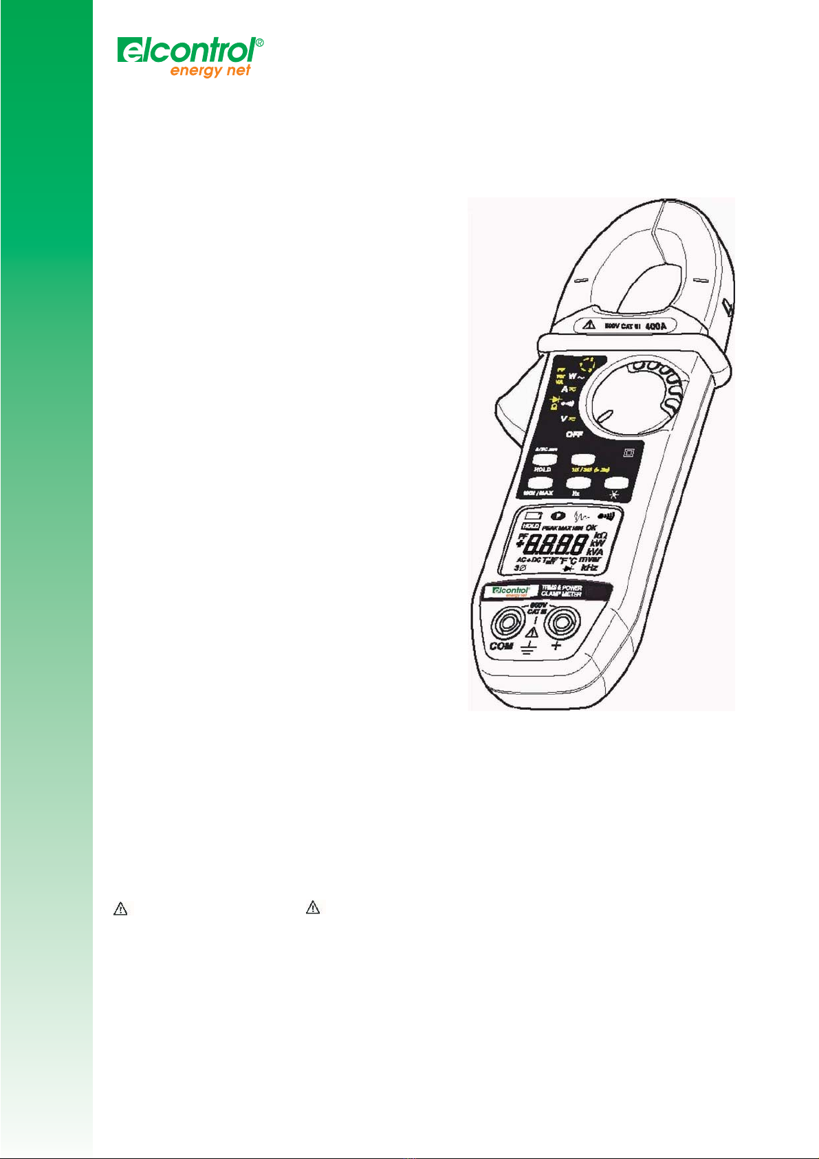
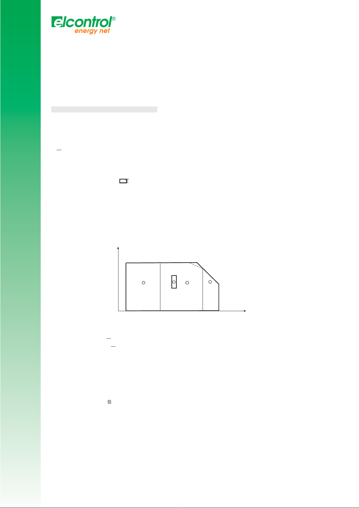
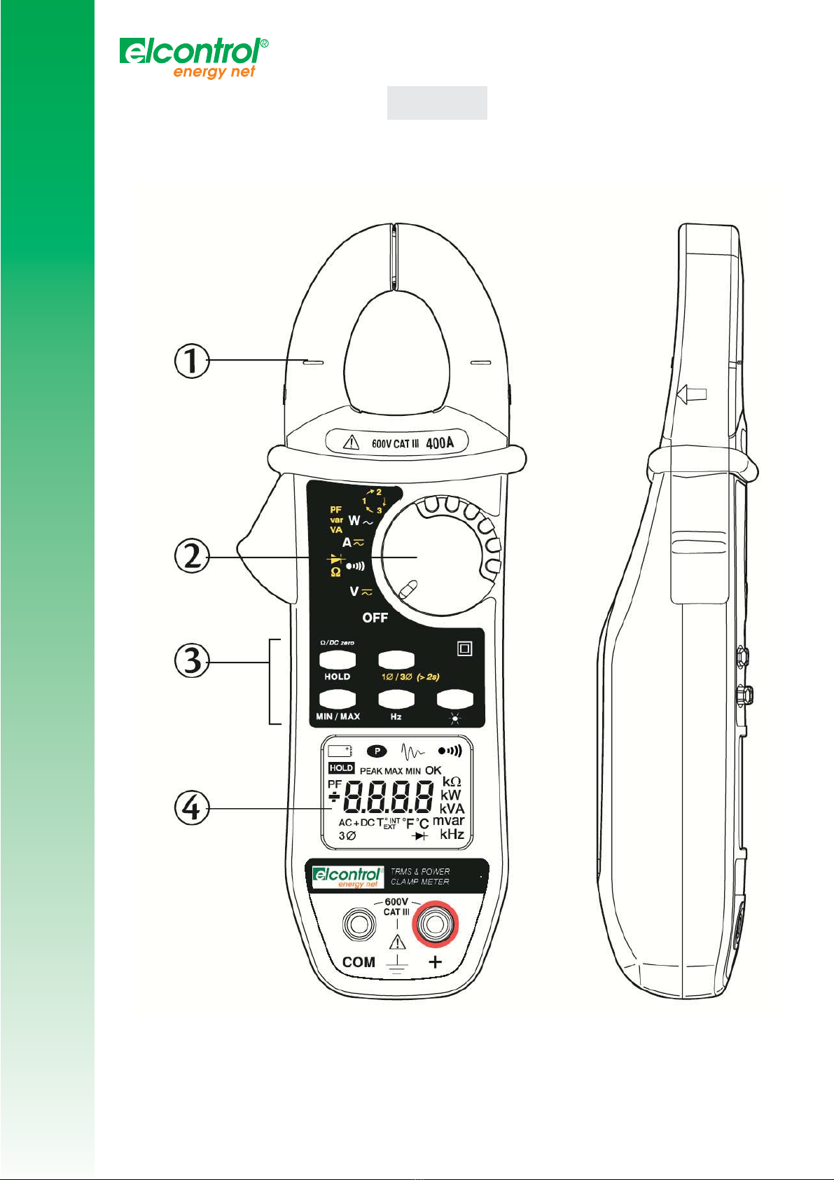
2. DESCRIPTION
(vedi schema § 8 Allegato)
Jaws
6-way rotary switch:
OFF Deactivation of the clamp, activation is ensured by selection of other functions
V Measurement of DC and AC voltages rms value)
Continuity measurement, by use of the yellow resistance key and semi-conductor test
A Measurement of DC and AC voltages rms value)
PF Measurement of active, reactive and apparent
var W~ powers and power factor in single phase or
VA balanced 3 phases systems by use of the yellow key)
Selection of phase order indicator for 3- phase system with or without neutral
Command keys
The keys are capable of 3 types of action:
Short pressure
>1.3 s, it is valid if the key pressure is detected
Long pressure
> 1.3 s, this gives access to a measurement or operating mode. Holding or releasing the key has no effect.
Held pressure
Gives access to a measurement or operating mode and remains in this mode as long as pressure is held. Releasing
the key causes return to the previous mode.
· HOLD has 4 different functions see description § 3.12):
- Display lock
- Preselection of MIN/MAX mode
- Automatic compensation for cable resistance
- Automatic compensation of current measurement zero
· The yellow key has 6 different functions (see also description § 3.12):
- Manual selection of AC, DC or AC+DC mode
- Selection of INRUSH function -Selection of resistance function W), semi-conductor test ontinuity test )
- Measurement of active, reactive, apparent powers and power factor calculation -Single phase or balanced three
phases systems selection
- Phase order indication measurement see description § 3.11)
· MIN/MAX operates by end-around shift on short pressure:
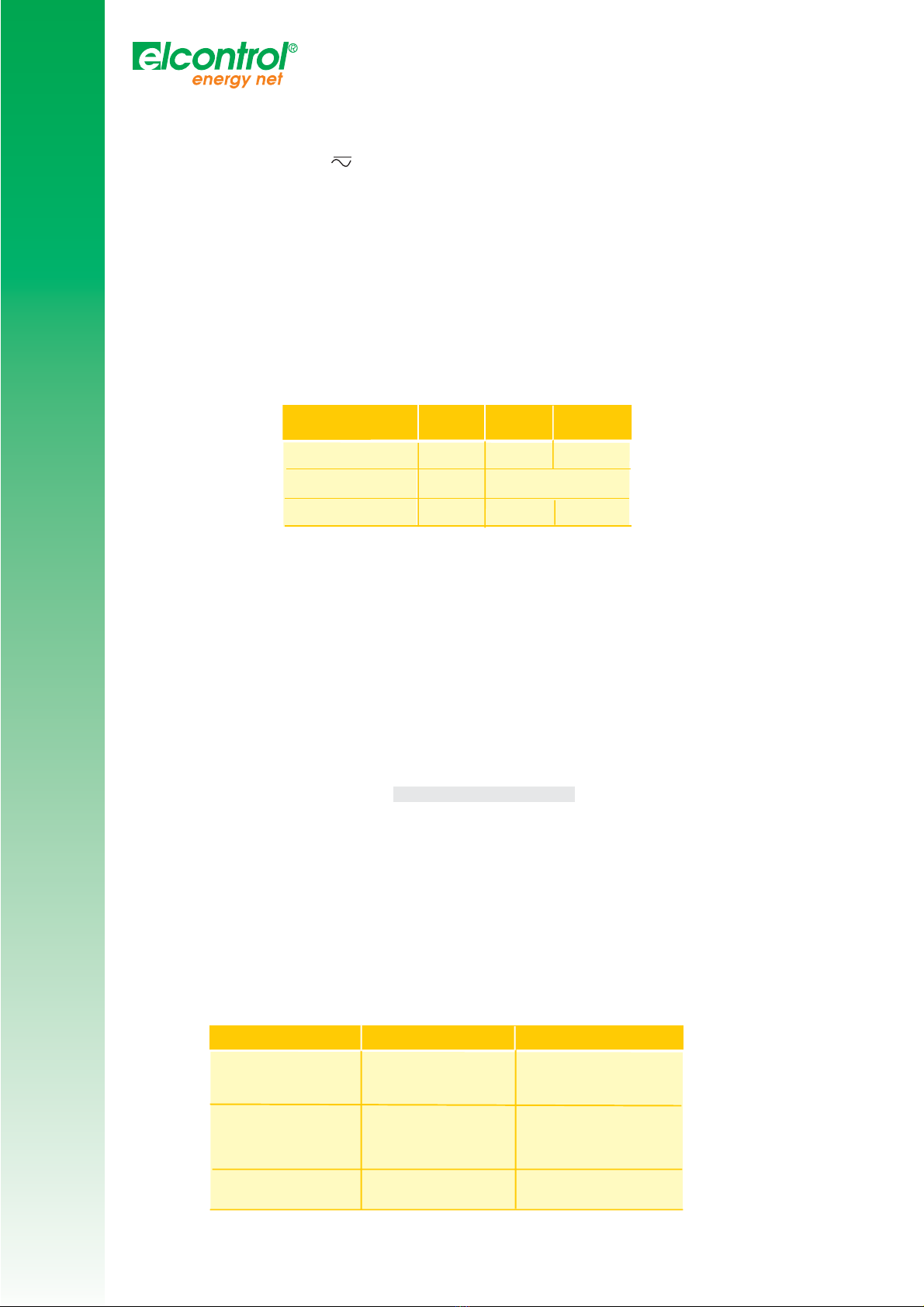
MIN/MAX Funzioni V e A Altre
Funzioni
PEAK value
a Press
2 a Press
3 a Press
4a Press
MAX value
MIN value
Return to PEAK value
MAX value
MIN value
Return MAX value
_
1
V
V
I
I
P
P
C
C
L
L
A
A
M
M
P
P
M
M
I
I
N
N
I
I
At any time, a long press on the key will quit the MIN/MAX mode.If the INRUSH function was selected see description
§ 3.7), a short pressure will return to MIN/MAX mode.
Note: In MIN/MAX mode, the Automatic stop function of the unit is unavailable symbol )
- Hz A short press displays the frequency of the measured signal, another press switches back to the previous value.
This key is active only for the AAC, VAC and W functions.
- Short pressure: display backlight command.
Automatic shutdown after 2 minutes.
Held pressure: display of estimated remaining battery power, expressed in hours except INRUSH
and phase order functions).
HOLD key/ switch combination see description § 3.12):
- Suppression of automatic stop function
- Activation of the V-Live function
- Display of the internal software version
Yellow key/ switch combination see description § 3.12):
- Modification of audio indication threshold in continuity test -Default configuration of the unit
MIN/MAX key/ switch combination
(see description § 3. 2):
-Date of last calibration performed on unit
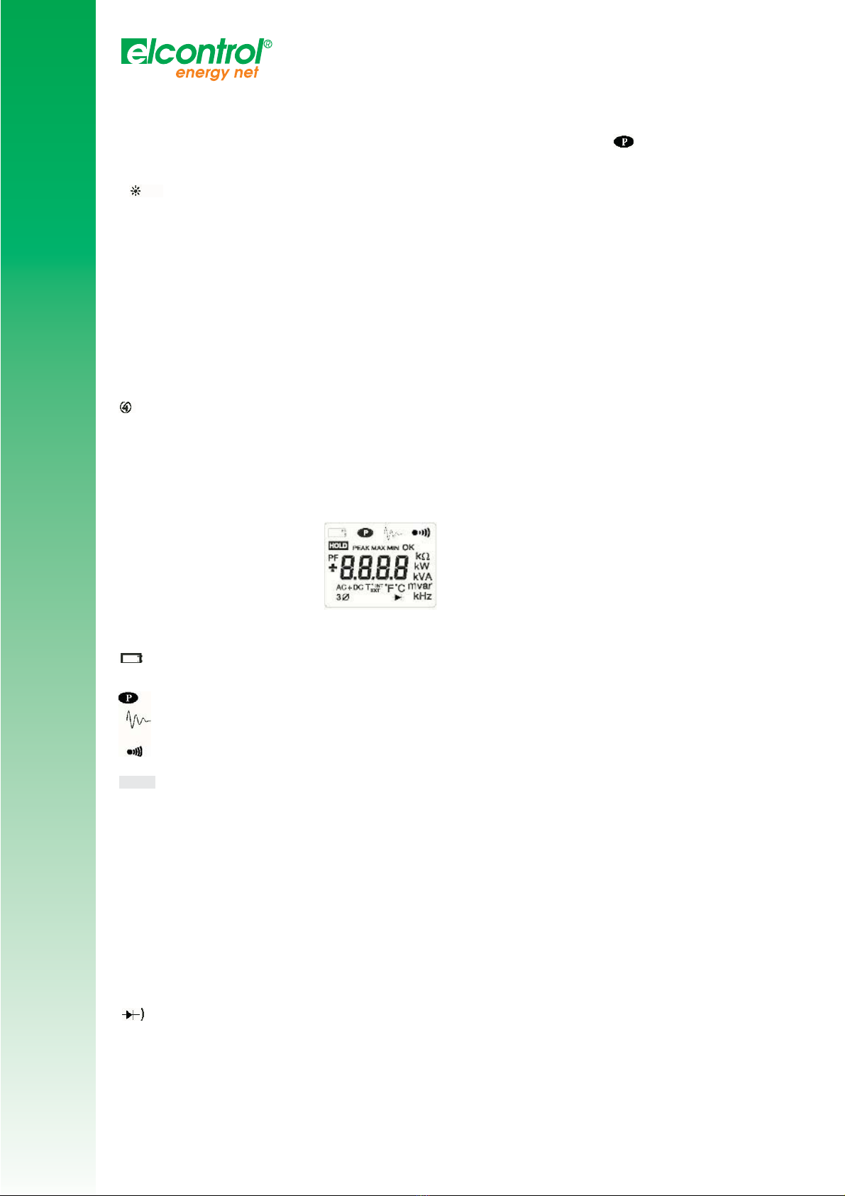
Liquid crystal display
The liquid crystal display includes the digital display of the measured values, the related units and symbols.
Digital display
4 digits, 9999 points, 3 decimal points , + and - signs DC and peak measurement).
+ OL: Positive value range exceedance > 3999 points)
- OL: Negative value range exceedance
OL: Unsigned value range exceedance
- - - -: Indeterminate value middle
Symbol display
Flashing, clamp power limited to approximately 1 hour
Steady, battery drained, clamp operation or accuracy no longer guaranteed
Constant operation no automatic shutdown)
ON steady when the INRUSH function is selected
Fixed: Continuity measurement
Flashing: V-Live function selected
HOLD Function active
PEAK ON in V and A in MIN/MAX mode if the measurement of the peak value is selected
MAX Indicates the display of a maximum value in MIN/MAX mode
MIN Indicates the display of a minimum value in MIN/MAX mode
OK Symbol which goes on during the phase rotation direction detection sequence W, if power factor display is
selected yellow key)
PF Goes on steady, for switch position
AC Measurement in AC manual mode
Flashing: measurement in AC automatic mode
DC Fixed: measurement in DC manual mode
Flashing: measurement in DC automatic mode
Semi-conductor test on position
3Ø Power measurement on balanced 3 phases system.
2
V
V
I
I
P
P
C
C
L
L
A
A
M
M
P
P
M
M
I
I
N
N
I
I
The Buzzer Different tones are emitted according to the function given to the buzzer:
- Short and medium sound: valid key
- Short and high-pitched sound: prohibited key
- Short and low sound: Quit MIN/MAX mode
- 2 short and high-pitched beeps: validation of a configuration parameter
- Short and medium sound every 400 ms: voltage measured higher than the units guaranteed safety voltage.
- 5 short and medium recurring beeps: automatic deactivation of the instrument
- Short and medium sound: measured continuity value, lower than programmed threshold, short-circuit junction
during semi-conductor test.
- Modulated medium continuous sound: value measured in volts, higher than 45 V peak when the V-Live
function is selected.
3. IMPLEMENTATION FUNCTIONAL CHARACTERISTICS
3. Reference conditions
The functional characteristics mentioned in each of the measurement functions are guaranteed in the following
reference ranges:
- Temperature: +23°C ± 3 K
- Humidity: 45% to 75% relative humidity
- Supply voltage: 8.5 V ± 0.5 V
- Frequency range of applied AC signal: 45 -65 Hz
- Peak factor of applied AC signal: Ö2 -
- Position of conductor in clamp jaws: centred
- Conductor diameter: '3d 5 mm -No external AC magnetic field
- No electrical field
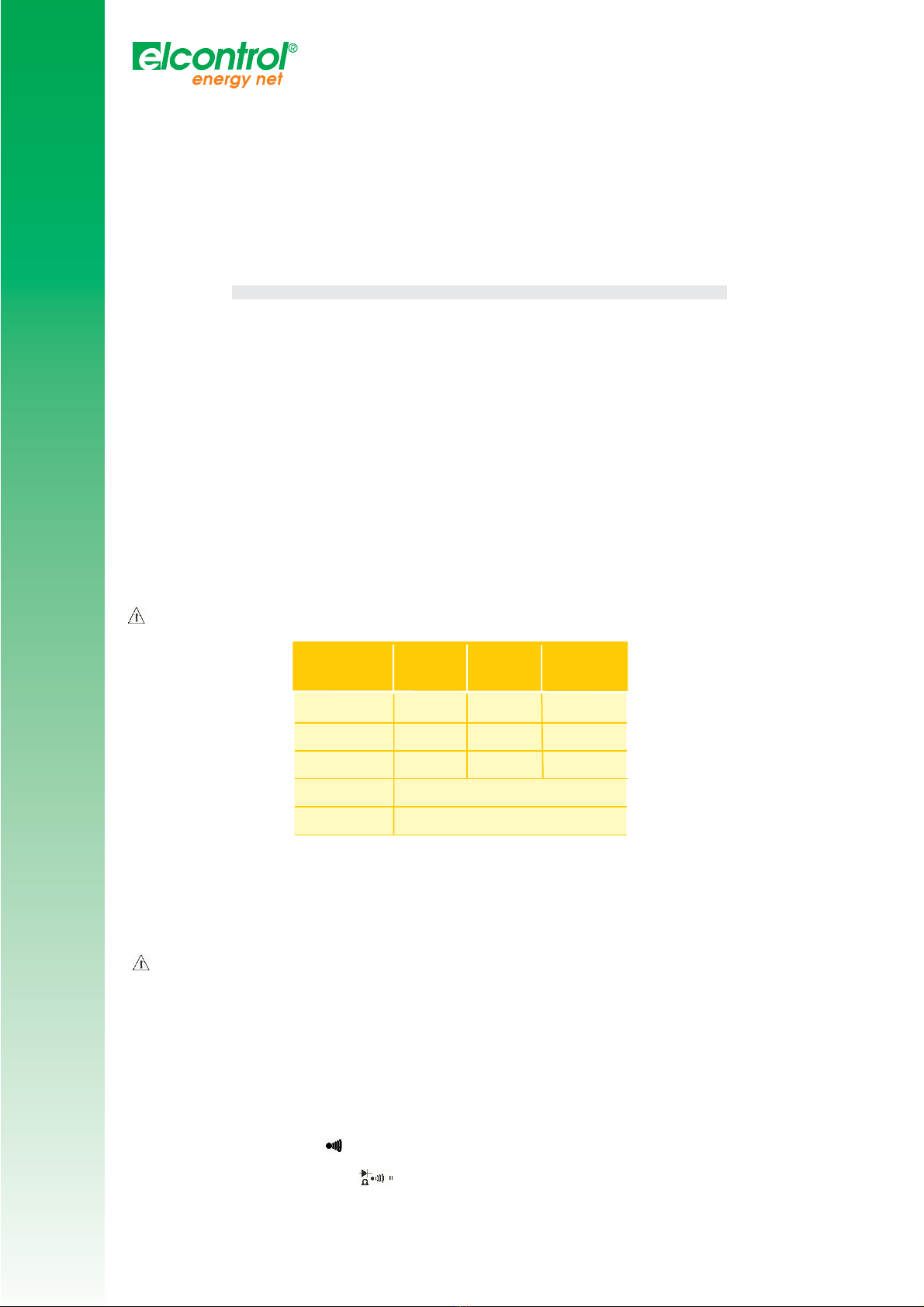
3.2 Voltage measurements (V)
. Connect the measurement leads to the instruments terminals, complying with the polarities indicated: red lead
on the + terminal and black lead on the COM terminal.
2. Set the rotary switch to position "V".
3. Connect the assembly to the voltage source to be measured, making sure if possible that this voltage does
not exceed the maximum acceptable limits see table below). Range switching and AC/DC selection are
automatic.
Actuate the yellow key to force AC, DC or AC+DC selection manually if necessary.
If the signal measured is > 45 V peak, the audio indication is activated if the V-Live function is selected
see § 3.12.9).
Display range
40 V 400 V 4000 V ( )
Measuring
range(2)
Accuracy
Resolutin
Input
impedance
Protection
0,2 V à
39,99 V
40,0 V à
399,9 V 400 à 600 V
400 à 900
1% L +5 pt
10 mV
1% L +2 pt 1% L +2 pt
0,1V 1V
1MW
600 V AC or DC
(1) In DC, the display indicates +OL a ove +600 V and -OL a ove -600 V (900 V in PEAK mode). In AC, the
display indicates OL over 600 Vrms (900 V in PEAK mode).
(2) In AC if the value of the voltage measured is < 0.15 V the display indicates 0.00.
For voltages 600 VDC or rms, a repetitive beep of the buzzer indicates that the measured voltage is
higher than the units guaranteed safety voltage.
§ MIN/ MAX Mode:
-Accuracy: same as previous table +0.2% L
-Capture time: 100 ms typ.
§ PEAK Mode:
- Accuracy: same as previous table +2% L
- Capture time: 500 µs typ. 2.5 ms max.)
§ Special characteristics in V-Live mode
- Detection threshold accuracy: 45 Vpeak ± 2V
3.3 Audio continuity test ( )
1. Connect the measurement cables to the unit terminals.
2. Set the rotary switch to position "
3. Connect the unit to the circuit to be tested. The buzzer is continuously active as soon as contact is established
circuit closed) and if the resistance value measured is lower than the threshold value chosen by the
pro rammin (adjustable from 1 to 40 W, see § 03.12.10). Above 400 W, the display indicates OL.
3
V
V
I
I
P
P
C
C
L
L
A
A
M
M
P
P
M
M
I
I
N
N
I
I
§ Cable resistance compensation ( zero) To measure low resistance values, measure the cable resistance first.
-Short-circuit the cables.
-Press and hold the HOLD key until zero appears on the display.The cable resistance value will then be
memorised and subtracted from the value of the resistance measured later.
Note: If the value measured is hi her than 2 W, this correction is stopped and the memorised correction value is reset to
zero.
(1) with compensation for measurement ca le resistance
MIN/ MAX Mode:
-Accuracy: same as previous table +0.2% L
-Capture time: 100 ms typ.
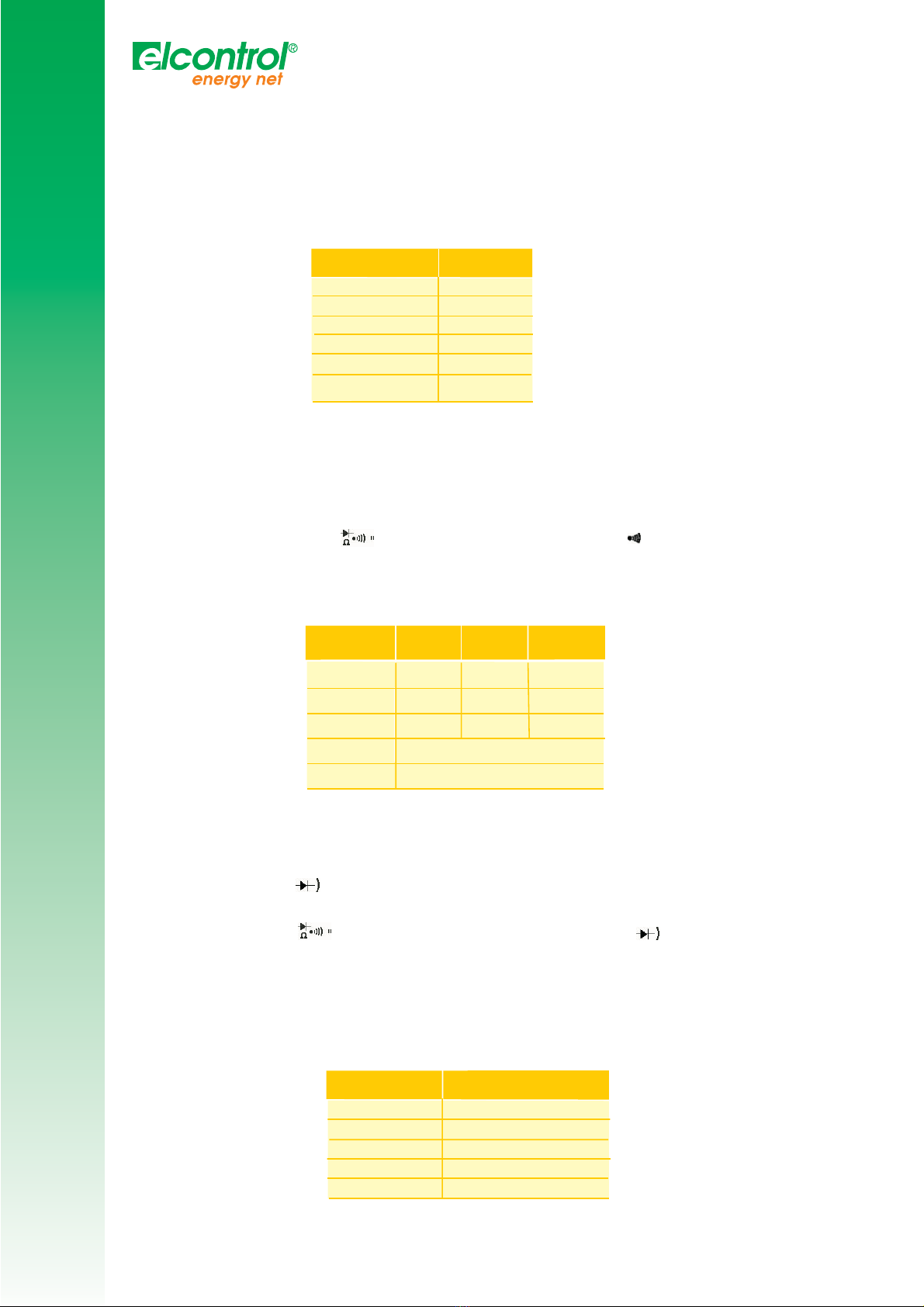
3.4 Resistance measurements (W,)
. Connect the measurement cables to the unit terminals.
2. Set the rotary switch to position " " and press once on the yellow key: The symbol is no longer displayed.
3. Connect the unit to the circuit to be tested. Range selection is automatic. To measure low resistance with accuracy,
compensate the cable measurement resistance see § 3.3). Above 40 W, the display indicates OL.
Display range
400 W
Measuring range
Accuracy ( )
Resolution
Open circuit voltage
Protection
0,0 à 399,9W
1% L ± 2 pto
0,1 W,
300 µA
Measuring current
3,2 V
500V AC o 750V
DC or peak)
MIN/ MAX Mode:
- Accuracy: same as previous table +0.2% L
- Capture time: 100 ms typ.
3.5 Semi-Conductor Test ( )
. Connect the measurement leads to the instruments terminals, complying with the polarities indicated: red lead
on the + terminal and black lead on the COM terminal.
2. Set the rotary switch to " " position and press twice on the yellow key: The symbol is displayed.
3. Connect the unit to the semi-conductor junction) to be tested.
The measurement current moves from the + terminals to the COM terminal. It corresponds to the direct
testing of the semi-conductor junction.
- Short-circuit junction: audio indication for a threshold <0.050V
- Cut or reversed junction or threshold > 3.2 V) : OL displayed
Display range
4V
Measuring range
Accuracy
Resolution
Protection
0,000 a 3,199V
1% L ± 2 pto
1mV
Measuring current 1)
da 2mA a 4mA
500V AC o 750V DC or peak)
(1) for the voltage measured
Display range 40 V 400 V 4000 V ( )
Measuring
range
Accuracy
Resolution
Measuring
current ( )
Protection
0,2 V à
39,99 V
40,0 V à
399,9 V 400 à 600 V
400 à 900
10 mV 0,1V 1V
1MW
600 V AC ou DC
1% L ± 2 pto
1% L ± 2 pto
1% L ± 5 pto
4
V
V
I
I
P
P
C
C
L
L
A
A
M
M
P
P
M
M
I
I
N
N
I
I
MIN/ MAX Mode:
-Accuracy: same as previous table +0.2% L
-Capture time: 100 ms typ.
3.6 Current measurements (A)
. Set the rotary switch to position "A "
2. Clamp the conductor carrying the current to be measured, check for proper closing of the jaws and for foreign
bodies in the gap. For DC, the arrow engraved on the jaws must be directed in the presumed direction of current
circulation for the sign of the displayed value to be significant.
Range switching and AC/DC selection are automatic. Actuate the yellow key to force AC, DC or AC+DC selection
manually if necessary.
Correction of the current measurement zero (DC zero)
To measure the low currents, perform a zero correction first. -Press and hold the HOLD key until zero appears on
the display. The corrected value will then be memorised and subtracted from the value of the current measured later.
Note: this correction is performed only on the DC component of the zero. If the value measured is higher than 6 A,
this correction is stopped and the memorised correction value is reset to zero.
(1) In DC, the display indicates +OL a ove +400 A and -OL a ove -400 A (600 A in PEAK mode).
In AC, the display indicates OL over 400 Arms (900 V in PEAK mode).
(2) In AC, if the value of the current measured is < 0.15 A, the display shows 0.00.
(3) With correction of zero in DC
- Repeatability of the measurement after several consecutive closings of the clamp: 0.3% typical
§ MIN/ MAX Mode:
- Accuracy: same as previous table +0.2% L
- Capture time: 100 ms typ.
§ PEAK Mode:
- Accuracy: same as previous table +2% L +0.5 A
- Capture time: 500 µs typ. 2.5 ms max.)
3.7 INRUSH function
§ Description
This function is used to follow quick changes in the current, such as a damped sinusoidal quantity, by measuring
the successive rms values calculated on ½, 1, 2½, 5 and 10 periods from the largest rms value computed and
updated on ½ period.
The applications are:
- Measurement of motor start-up currents
- Correct definition of fuses and circuit breakers signal amplitude-time relationship)
- Stress on components by current overload
The field of application is limited to industrial frequencies 15 Hz... 70 Hz)
Implementation
This function is accessible in AC current measurement only, after selection of the MIN/MAX mode.
Characteristics
Display range 40A
Measuring range 2)
Accuracy 3)
Resolution
0,20 a
39,99 V
40,0 a
3999,9 A
400 A
600A peack
1,5% L
+10 pto
10mA 100mA 1mA
4000
W
40
W
1,5% L +5 pto
5
Press the yellow key
Action Display Comments
0,5 P then the value
for rms corresponding
out F
Enter the function
Signal frequency
< 15 Hz o > 70 Hz
Press on HOLD key then
press successively the
yellow key
1P-2,5P-5P-10P-0,5P
with each time
the rms value
corresponding alternately
Consultation of values rms
computes on of
consecutive periods)
Short pressure
on the MIN/MAX key
Return to values
MIN,MAX or PEAK
Exit from the function
return to MIN/MAX mode

V
V
I
I
P
P
C
C
L
L
A
A
M
M
P
P
M
M
I
I
N
N
I
I
Characteristics
- Accuracy: 5% +0.5 A
-Capture time: 10 periods of the signal frequency 200 ms at 50 Hz)
- Range for use: ³'3d 5 A peak for the first period of the signal
3.8 Power measurement (W var VA)
. Connect the measurement leads to the instruments terminals, complying with the polarities indicated: red lead
on the + terminal and black lead on the COM terminal.
2. Set the rotary switch to position W single phase measurement).
3. Make a long press on the yellow key for measurement on balanced 3 phases system.
4. Connect the clamp on the system selected for power measurement, complying with the following instructions:
SINGLE PHASE SYSTEM
-Connect the measurement cables for voltage measurement, red cable on phase, black cable on neutral. -Clamp
the conductor carrying the current to be measured, check for proper closing of the jaws and for foreign bodies in
the gap.
BALANCED 3 PHASES SYSTEM
- Connect the measurement cable for voltage measurement, red cable on phase 1, black cable on phase 2 U12
measurement).
- Clamp the conductor of phase 3 I3 measurement).
Nota : same results are achieved with the following couples of measurement : U23 with I1 and U31 with I2.
In both cases the '3f arrow on the jaws, must be directed in the direction of power circulation from the source
to the load. In which case:
- the + sign corresponds to power consumed by the load.
- the - sign corresponds to power supplied by the load.
Specific reference conditions
PF = 1; I ³'3d 2 A; U ³'3d 10 V
Active power measurement characteristics
Display range 4000W
Measuring range(2)
Accuracy (3)
Resolution
5a
3999 W
4,00 kW
39,99 kw
2% L +1 pt
1W
40
kW
400 kW
40,0 kW a
240,0kW - 399,9kW 1)
10W 100W
Display range 4000W
Measuring range(2)
Accuracy (3)
Resolution
5a
3999 var
4,00 kvar a
39,99 kvar
2% L +1 pt
1var
40
kW
400 kW
40,0 kvar a
240,0kW - 399,9kvar 1)
10var 100var
Reactive power measurement characteristics
Apparent power measurement characteristics
Display range 4000W
Measuring range(2)
Accuracy (3)
Resolution
5a
3999 VA 4,00 kvar a
39,99 kVA
2% L +1 pt
1VA
40
kW
400 kW
40,0 kvar a
240,0kW - 399,9kVA 1)
10VA 100VA
1) the scale is limited to 240 kW kvar, kVA) in one-phase 600 V x 400 A) and 399.9kW kvar kVA) in 3
phases system. Above this value, the display indicates +OL or -OL depending on the sign of the
power.
2) if the power value is < 5 W or if the voltage or current values are respectively < 0.15 V or < 0.15 A, 0
is displayed.
3) The measurement accuracy is affected by an instability linked to current measurement of approximately
0.1 A.
Example: for a power measurement performed at 10 A, the instability of the measurement will be 0.1
A/10A, or 1%.
6

V
V
I
I
P
P
C
C
L
L
A
A
M
M
P
P
M
M
I
I
N
N
I
I
MIN/ MAX Mode:
- Accuracy: same as previous table +0.3% L
- Capture time: 100 ms typ. every 400 ms)
3.9 Power factor calculation (PF)
With the clamp configured in power measurement switch on position W) and correctly connected see § 3.8),
perform a short press on the yellow key: the power factor is displayed.
Display range
Measuring range( )
Accuracy
Resolution
0,20 a
0,49
0,50 a
1,00
5% L +2 pt
,00
0,01
5% L +2 pt
Characteristics
1) The display of the power factor is limited to 1.00 If one of the terms of the power factor calculation is outside its
power range, the display of the power factor indicates an indeterminate value- - - -.
MIN/ MAX Mode:
-Accuracy: Same for the table below + 1 pt
-Capture time: 100 ms typ. every 400 ms)
3. 0 Frequency Measurement (Hz)
This function is active for measurements V, A, W in AC. For the power function, the frequency measurement is
performed on the voltage signal.
. Perform a short pressing on the Hz key, the display shows the frequency of the measured signal.
2. Pressing again returns to the previously displayed measurement.
Display range 40 Hz
Measuring range( )
Accuracy
Resolution
10,00 a
39,99 Hz
0,4% L +1 pt
0,01 Hz
400 Hz 4000 Hz
Triggering threshold (2)
5V ou 10A
0,1 Hz 1 Hz
40kHz
40,0 a
399,9 Hz
400 a
3999 Hz
4,00 kHz a
19,99 Hz
10 Hz
1) Below 5 Hz, the display shows 0.0
(2) Below the triggering threshold, the display shows an indeterminate value (- - - -).
MIN/MAX
- Accuracy: same as in the table above +0.2% of reading with limitation to 5 kHz.
- Capture time: 125 ms typ. every 400 ms
3. Phase order indication
This measurement is performed with 2 cables only, sequentially as follows:
. Integration of a reference period on one phase L1-L2 for example
2. Integration of a reference period on one phase L1-L3
3. Calculation of the time delay between reference and measurement periods enabling determination of the phase
order or phase rotation direction.
7
Characteristics

V
V
I
I
P
P
C
C
L
L
A
A
M
M
P
P
M
M
I
I
N
N
I
I
- Special reference condition
-3-phase and sinusoidal network with 50 Hz or 60 Hz stable frequency
Characteristics
- Frequency range: 47 Hz to 53 Hz or 57 Hz to 63 Hz.
- Acceptable voltage range: 50 V to 600 V
- Acceptable phase imbalance rate: ±10°
- Acceptable amplitude imbalance rate: 20%
- Acceptable voltage harmonic distortion: 10%
Running of phase rotation direction detection sequence
Note 1:
In the following ta le, display of the sym ol refers systematically to the eginning of sequence
Note 2:
The sequence of the following ta le is descri ed using:
- L1 on terminal COM
- L2 then L3 on terminal + The same result is o tained if:
- L2 on terminal COM , L3 then L1 on terminal + or:
- L3 on terminal COM , L1 then L2 on terminal +
Note 3:
The measurement principle is ased on a certain frequency sta ility and practically sinusoidal signals (THD < 10%).
This excludes in particular measurement on power generators whose spin sta ilisation system is too weak to ensure
adequate frequency sta ility.
3. 2 Secondary Functions
3. 2. Display lock
A short pressing on the HOLD key freezes the display.
A second pressing unlocks the display.
3. 2.2 Preselection of MIN/MAX mode
A short pressing on the HOLD key then on the MIN/MAX key preselects the MIN/MAX mode. A second pressing
on the HOLD key makes the MIN/MAX mode effective.
This function is used to select the MIN/MAX mode upon request to prevent, for example, the unwanted or mistaken
integration of MIN/MAX values.
Action Display
Switch on the position 1 2 3
Press the yellow key
Cable connected black on
L1 and contact
displays red cable on L2
Comments
Red cable contact on L3
less than 10 seconds
after leaving L2
rEF
ErrV 2 s)
poi Err Hz 2 s)
poi rEF OK
MEAS
ErrV 2 s) then
Err Hz 2 s) then
Err 1.2.3
3.2.1
Enter the function
The unit is ready to detect the
reference period
The unit determines the period
measurement, the following messages
may be displayed after 10 s max):
-- determination of period for
measurement in progress
-- ontact on L3 a was performed too late
more than 10 s after display rEF OK)
-- voltage incorrect
-- equency incorrect
-- dtermination of phase direction
impossible
-- direct direction of phase rotation
-- reverse direction of phase rotation
Return to beginning of sequence
valid at all times in the sequence)
Press yellow key
8
after 10 seconds maximum result is one
of the 3 following opposite:
-- if voltage < 50 V
-- if niminal freq.50 Hz or 60 Hz
-- reference period correct

V
V
I
I
P
P
C
C
L
L
A
A
M
M
P
P
M
M
I
I
N
N
I
I
3. 2.3 Automatic compensation for cable resistance
This compensation is obtained by holding down the HOLD key when the continuity test or measurement resistance
function is selected.
When the key is released, when the display shows zero, the correction value is memorised in the clamp.
If the value measured is higher than 2 W) this correction is stopped and the memorised correction value is reset to
zero.
This correction is prohibited in MIN/MAX mode.
3. 2.4 Automatic compensation of current measurement zero
This compensation is obtained by holding down the HOLD key when the current measurement function is selected.
When the key is released, when the display shows zero, the correction value is memorised in the clamp.
If the value measured is higher than 6 A, this correction is stopped and the memorised correction value is reset to zero.
This correction is prohibited in MIN/MAX mode.
3. 2.5 Manual selection of AC, DC or AC+DC mode
By default the clamp switches to AC or DC mode automatically AC or DC symbol flashing) for the V and A functions.
Short successive pressures on the yellow key are used to select manually AC measurement, DC measurement of compound
signals AC+DC) and return to automatic mode. When the mode is selected manually, the AC, DC or AC+DC symbol is
fixed. The selection of this manual mode is impossible in MIN/MAX or HOLD mode.
3. 2.6 3. 2.6 Selections possible in continuity function
By default the clamp is in continuity function ) for the position corresponding to the rotary switch. Successive presses
on the yellow key enable selection of the resistance measurement W), then the semi-conductor test function )
and return to the continuity function )
3. 2.7 Selection OF INRUSH function
This is done in function A AC) by pressing first on the MIN/MAX key then on the yellow key.
Consultation of the values corresponding to this function is possible by pressing first on the HOLD key then by short
successive presses on the yellow key see § 3.7).
Quitting this function is possible by short presses on the MIN/MAX key.
3. 2.8 Suppression of automatic stop
Hold the HOLD key pressed and bring the rotary switch from the OFF position to the position The unit emits a double
beep then the symbol flashes. The selected configuration is memorised when the key is released: the
symbol remains lit continuously. The unit returns to automatic stop mode when the switch goes to the OFF position .
Lapparecchio emette un duplice bip quindi il simbolo lampeggia.
La configurazione scelta viene memorizzata quando si rilascia il tasto : il simbolo è acceso fisso.
Lapparecchio ritorna in modo arresto automatico quando il commutatore passa sulla posizione OFF.
3. 2.9 Activation of the V-Live function
Hold the HOLD key pressed and bring the rotary switch from the OFF position to the V position.
The unit emits a double beep then the V and symbol flashes.
The selected configuration is memorised when the key is released: the V symbol is then ON steady and the symbol
flashes. Proceed in the same way to suppress the V-Live function: the symbol then goes OFF when the key is
released.
3. 2. 0 Modification of audio indication threshold in continuity test
Hold the Yellow key pressed and bring the rotary switch from the OFF position to the position
. The unit beeps, the W and symbols go ON along with the threshold value 40.0 by default). Adjustment is then possible
from 1 W to 40 W by successive pressings on the yellow key short pressure: progression of 1 W by 1 W; press and hol
hold: progression of 10 W by 10 W). Once the value is chosen, actuate the rotary switch to memorise.
3. 2. Default configuration of the unit
Hold the Yellow key pressed and bring the rotary switch from the OFF position to A position.
The unit emits a double beep then all the segments of the digital display and the symbol flash.
The default configuration is memorised when the key is released: the display no longer flashes and the
symbol disappears.
The default configuration is:
- Audio identification threshold: 40 W
- Auto cut-off: with
- V-Live function: none
3. 2. 2 Date of last calibration carried out on unit
Hold the MIN/MAX key pressed and bring the rotary switch from the OFF position to the V position.
The unit emits a beep, then the calibration date of the unit is displayed in the form week - year SS.AA) as long as the
MIN/MAX key is pressed.
9
V
V
I
I
P
P
C
C
L
L
A
A
M
M
P
P
M
M
I
I
N
N
I
I
3. 2. 3 Display of the internal software version
Hold the HOLD key pressed and bring the rotary switch from the OFF position to the A position . The unit beeps,
the software version is displayed in the form UX.XX for 2 seconds, then all the segments of the display are shown
as long as the HOLD key is pressed.
3. 2. 4 Showing of display segments
See § 03.12.13. It is usually possible for any key-switch combination not described previously.
4. GENERAL SPECIFICATIONS
4. Dimensions and weight
70 x 193 x 37 mm 260 g
4.2 Clamp Tightening Capacity
<26 mm
4.3 Power Supply
a standard 9 V alkaline battery type CEI 6LF22, 6LR61 or NEDA 1604).To change it, see §7.1.
Average battery charge life: 60 h or 20,000 x 10 s measurements
6 Battery charge indicator
Flashing: charge life < 1 h Fixed: Change battery
Automatic OFF after 10 minutes with no action on the switch or the keys reactivation by switching from the OFF
4.4 Environmental parameters
Temperature - Humidity
Altitude
- Operation:
<2.000 m
- Storage: < 12000 m
Indoor use
Impermeability: protection index IP 40 according to EN 60529, ed. 92)
4.5 Compliance with norms
Electrical safety:
secondo EN 61010-1, ed. 2001 e EN 61010-2-032, ed. 2003
- Dual insulation:
- Installation category: 600 V CAT III o 300 V CAT IV
- Pollution level: 2
Electromagnaetic compatibility
- as for EN 61326-1, ed. 2006
Mechanical resistance
- Free fall 1 m (test as for IEC 68-2-32)
- Shock : 0,5 J (test as foro IEC 68-2-27)
- Vibrazioni : 0,75 mm (test as for IEC 68-2-6)
Auto- power OFF (for UL94)
- Housing: V0
- Jaws: V0
- Display window: V2
Temperature in °C
0
1
2
3
3
20
10
30
40
50
60
70
80
90
-50 -40 -30 -20 -10 0 10 20 30 40 50 60 70 80 90
Relative humidity in % HR
10
V
V
I
I
P
P
C
C
L
L
A
A
M
M
P
P
M
M
I
I
N
N
I
I
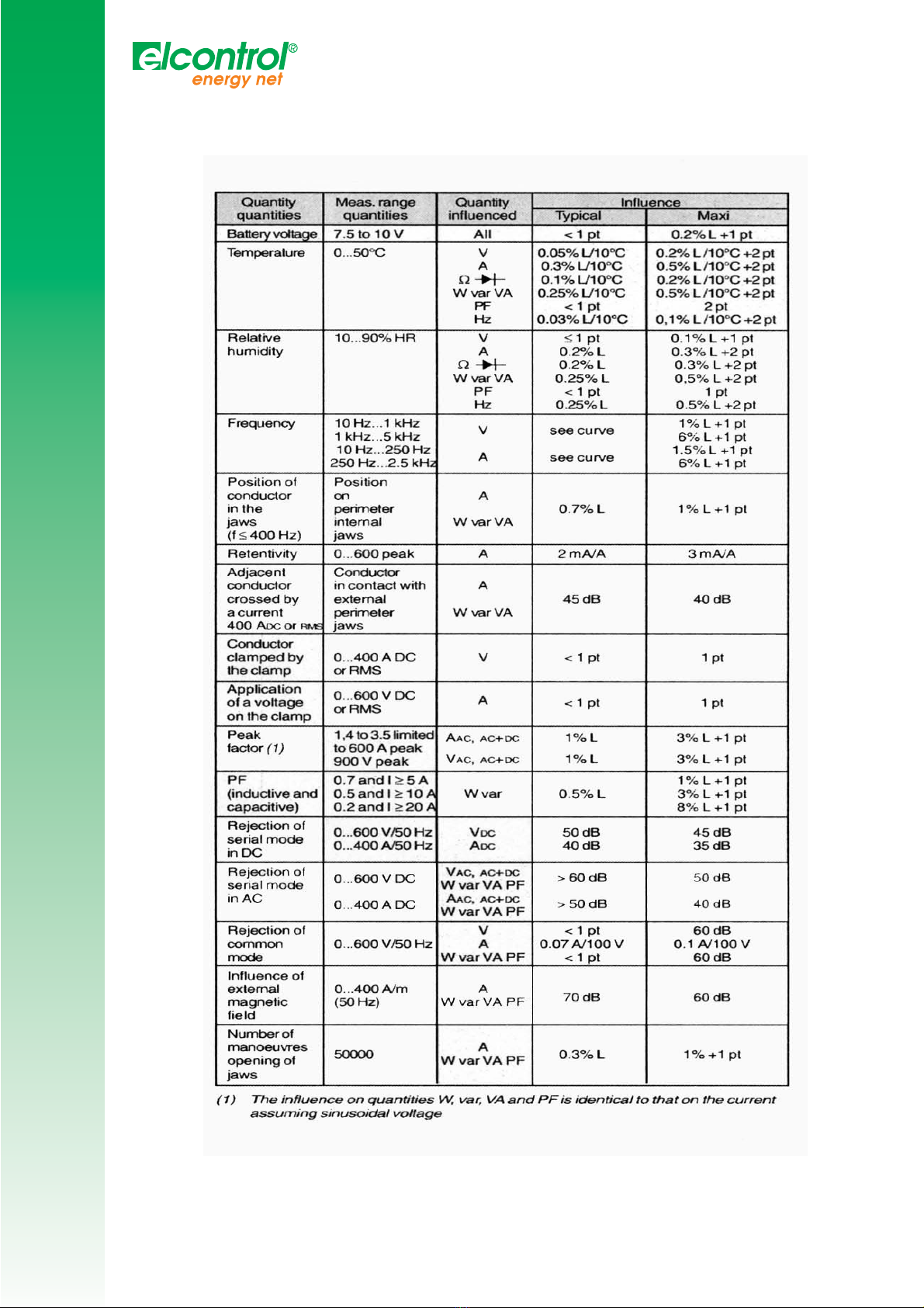
4.6 Variations in operating range
11

V
V
I
I
P
P
C
C
L
L
A
A
M
M
P
P
M
M
I
I
N
N
I
I
Tipica frequency responce curve
-V f f)
5. GUARANTEE
Our guarantee is applicable for twelve months after the date on which the equipment is made available extract
from our General Conditions of Sale, available on request).
6. MAINTENANCE
For maintenance, use only specified spare parts. The manufacturer will not be held responsible for any accident occuring
following a repair done other than by its After Sales Service or approved repairers.
6. Changing the battery
The clamp must be disconnected from any external electrical source and must not be in contact with the cable.
- Set the switch to OFF
- Slide a screwdriver into the slot at the top of the battery cover rear of the clamp) and push the battery cover upwards.
- Replace the used battery by a 9 V battery, type LF22; observe the polarities.
- Install the battery in its housing, then install the battery cover.
6.2 Storage
If the clamp is not used for a period of more than 60 days, remove the battery and store it separately.
6.3 Cleaning
- The clamp must be disconnected from any external electrical source and must not be holding the cable.
Clean the unit and jaws with a cloth slightly moistened with soapy water. Clean off with a damp cloth.
Then dry quickly with a cloth or pulsed air.
- Do not splash water onto the clamp.
- Keep the gap between the jaws in a state of perfect cleanliness.
Repair
For all repairs before or after expiry of warranty, please return the device to your distributor.
4.7 Marginal operating conditions
Clamped conductor temperature: 110°C
12
V
V
I
I
P
P
C
C
L
L
A
A
M
M
P
P
M
M
I
I
N
N
I
I
APPENDIX
APPENDIX
13
Table of contents
Popular Multimeter manuals by other brands

Fluke
Fluke 8845A Calibration manual

Maxwell Digital Multimeters
Maxwell Digital Multimeters MX 25 312 user manual

MARTINDALE
MARTINDALE MM42 operating instructions

APPA
APPA 33II instruction manual

Gossen MetraWatt
Gossen MetraWatt METRALINE DM 61 operating instructions

PeakTech
PeakTech 4090 Operation manual


