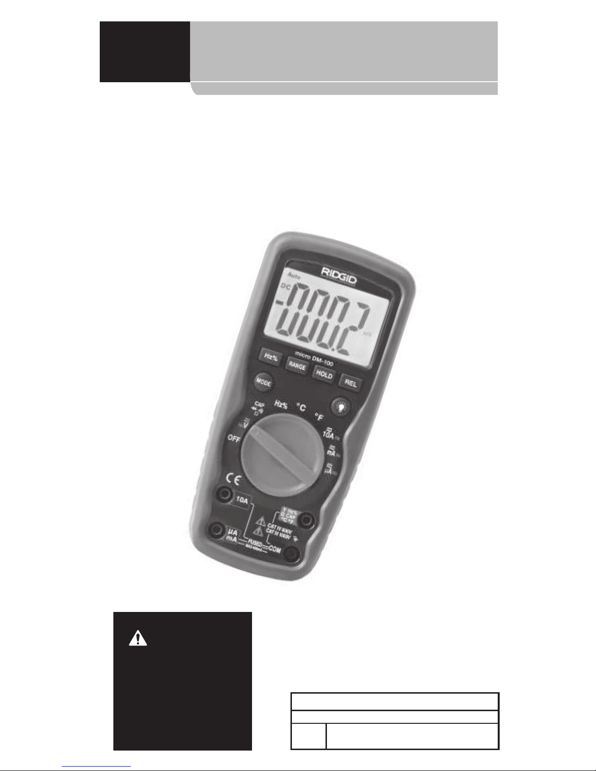
micro DM-100 Digital Multimeter
2
Lifetime Warranty...................................................................................................... Back Cover
*Original instructions
Table of Contents
Table of Contents........................................................................................................................... 2
Safety Symbols................................................................................................................................ 3
General Safety Rules.................................................................................................................... 3
Work Area Safety.......................................................................................................................... 3
Electrical Safety............................................................................................................................. 3
Personal Safety.............................................................................................................................. 3
Equipment Use and Care.......................................................................................................... 4
Service.............................................................................................................................................. 4
Specic Safety Information...................................................................................................... 4
Multimeter Safety ........................................................................................................................ 4
Description, Specications And Standard Equipment.............................................. 5
Description ..................................................................................................................................... 5
Specications................................................................................................................................. 5
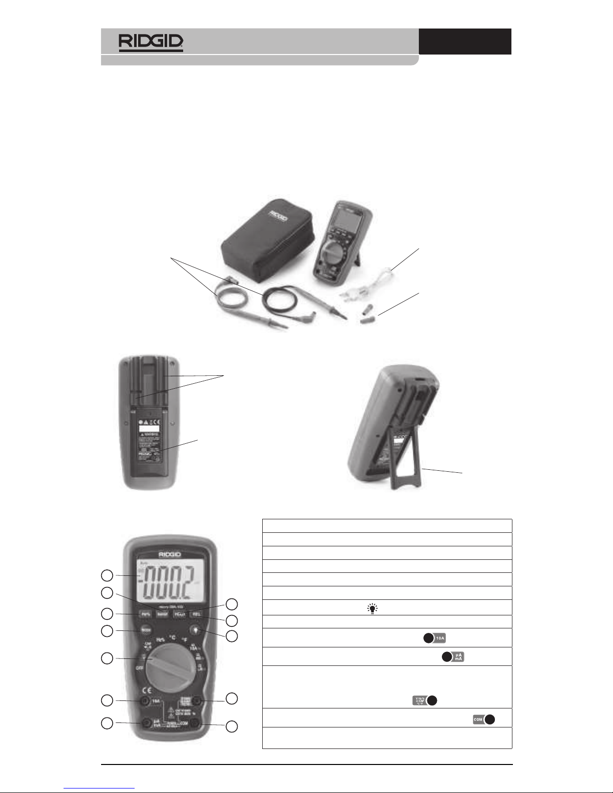
Standard Equipment .................................................................................................................. 8
Controls............................................................................................................................................ 8
Icons .................................................................................................................................................. 9
FCC Statement...............................................................................................................................10
Electromagnetic Compatibility (EMC)..............................................................................10
Changing/Installing Batteries...............................................................................................10
Pre-Operation Inspection .......................................................................................................11
Set-Up and Operation ...............................................................................................................12
Rotary Function Switch................................................................................................................13
Input Terminals ...........................................................................................................................13
Pushbuttons.................................................................................................................................14
DC/AC Voltage Measurement...............................................................................................14
DC/AC Current Measurement...............................................................................................15
Resistance Measurement........................................................................................................15
Diode Test......................................................................................................................................16
Continuity Check........................................................................................................................16
Capacitance Measurement....................................................................................................16
Frequency Measurement........................................................................................................17
Temperature Measurement...................................................................................................17
Maintenance Instructions .......................................................................................................18
Cleaning.........................................................................................................................................18
Calibration.....................................................................................................................................18
Fuse Replacement .....................................................................................................................18
Accessories......................................................................................................................................18
Storage ..............................................................................................................................................19
Service and Repair.......................................................................................................................19
Disposal.............................................................................................................................................19
Battery Disposal...........................................................................................................................19
Troubleshooting...........................................................................................................................20