Caviblaster 1325-D Manual

CAVIDYNETM, LLC
5077 Fruitville Rd., Suite 109-157
Sarasota, FL 34232
Phone: 352) 275-5319
Operation &
Maintenance
Manual
Model 1325-D

LLC is not responsible for damages or
injuries resulting from a failure to comply with
instructions in this manual. Please read and study the
entire manual carefully before use.
® 1325-D must only be operated
and maintained by trained personnel.
use only. Serious personal
injur or death ma result from improper use.
!
® system.
CAUTION: DO NOT USE THIS EQUIPMENT TO CLEAN
SENSITIVE SURFACES as LED-Lights, Underwater
Lights, Electronic Equipment, Etc.
Page - 2
CaviBlaster 1325-D Operations Manual
For More information please email sales@cavidyne.com or call 1- 352)275-5319

TABLE OF CONTENTS
1.0 UNIT SPECIFICATIONS ........................................................................................................ 5
2.1 GENERAL DESCRIPTION .................................................................................................... 6
2.2 Using this Manual Version 1.3) ......................................................................................... 8
2.3 Conventions ........................................................................................................................ 9
2.4 Scope .................................................................................................................................. 9
2.5 Terms and Abbreviations .................................................................................................... 9
3.1 SAFETY INFORMATION ..................................................................................................... 10
3.2 Personal Safety ................................................................................................................ 10
3.3 Personal Protective Equipment PPE) .............................................................................. 11
3.4 Modification to the Equipment .......................................................................................... 12
4.1 INSTALLATION ................................................................................................................... 13
4.2 Uncrating and Lifting ......................................................................................................... 13
4.3 Installation Location .......................................................................................................... 14
4.4 Initial Set-Up ..................................................................................................................... 15
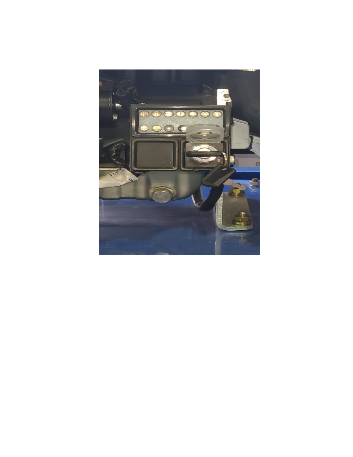
4.4.1 Connecting the Battery Terminals .............................................................................. 15
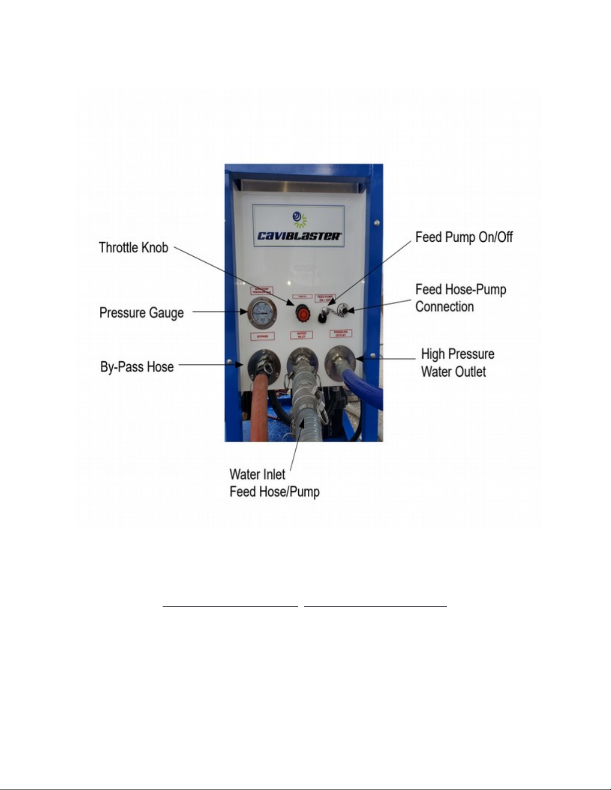
4.4.2 Connecting the Water Source .................................................................................... 17
5.1 OPERATION ........................................................................................................................ 20
5.2 Preparing the CaviBlaster ®
for Operation ........................................................................ 20
5.3 Startup of the CaviBlaster ®
........................................................................................................... 21
5.4 Normal Operation ............................................................................................................. 22
5.5 Adjusting the CaviBlaster ®
for
Maximum Performance ................................................... 24
5.6 Recommendations for Effective Results .......................................................................... 28
6.1 MAINTENANCE ................................................................................................................... 31
6.2 Basic Preventive Maintenance Recommendations .......................................................... 32
6.3 Diesel Engine Service ...................................................................................................... 33
6.4 Pump Service ................................................................................................................... 33
6.5 Inspection/Cleaning of Water Inlet Strainer ...................................................................... 33
6.6 Inspection / Maintenance of the Zero-Thrust Gun ............................................................ 36
7.0 WINTERIZATION ................................................................................................................. 37
8.0 TROUBLESHOOTING..........................................................……………………………...…38
9.0 REPLACEMENT PARTS ..................................................................................................... 40
APPENDIX - COMPONENT LITERATURE .............................................................................. 41
Page - 3
CaviBlaster 1325-D Operations Manual
For More information please email sales@cavidyne.com or call 1- 352)275-5319

LIST OF FIGURES & TABLES
Figure 2.1 – CaviBlaster® 1325-D General Features........................................................7
Figure 2.2 – CaviBlaster® 1325-D Ignition Box & Hose Connections...............................
Figure 4.1 – Lifting Guidelines.........................................................................................13
Figure 4.2 – Installation Guidelines.................................................................................14
Figure 4.3 – Reconnecting the Battery Terminals...........................................................16
Figure 4.4 – Gravity Feeding Source..............................................................................17
Figure 6.1 – Inspection / Cleaning Water Filter...............................................................35
Figure 6.2 – Clean - Dirty / Inlet Water Filter...................................................................36
Figure 6.3 – Zero-Thrust Gun..........................................................................................37
This space intentionall left blank
Page - 4
CaviBlaster 1325-D Operations Manual
For More information please email sales@cavidyne.com or call 1- 352)275-5319

1.0 UNIT SPECIFICATIONS
The CaviBlaster® 1325-D power unit comprises a 23.7HP 17.7 kW) Kohler diesel
power-pack and a UDOR CKC 50/20S triplex plunger pump. Detailed performance and
specifications are listed below:
CaviBlaster® 1325-D Specifications
Nominal Pump Flow 13 GPM 50 LPM)
Nozzle Operating Pressure 2,500-PSI 172 BAR)
Engine 23.7 HP Diesel Powered Kohler KDW1003)
Installation Environment Outdoor enclosed or exposed
See Section 4 for installation requirements
Fuel Requirements Diesel fuel ASTM Grade No. 1-D or 2-D, or EN 590)
Fuel Tank Capacity 13 Gallons 50 Liters)
Water Inlet Pressure Limits 0-PSI Atmospheric Pressure) to 50-PSI Maximum
0 BAR to 3.5 BAR) See Section 4 for further requirements
Overall Unit Dimensions L x W x H) 56” x 24” x 42”
Maximum Pressure Hose Length 328 LF 100 meters) of 1/2” 12.7 mm) diameter thermoplastic
Power Unit Weight Dry) 700 LBS 320 KG)
Zero-Thrust Gun Weight 4.4 LBS 2 KG)
Figure 1.1 – CaviBlaster® 1325-D Specifications
(EOS)
Page - 5
CaviBlaster 1325-D Operations Manual
For More information please email sales@cavidyne.com or call 1- 352)275-5319

GENERAL DESCRIPTION
The CaviBlaster® 1325-D high-pressure water power unit allows the operator to use the
water flow and pressure to generate cavitation at the end of the proprietary nozzle.
The CaviBlaster® cleans the surface of any underwater structure using the energy
released by the implosion of the cavitation bubbles during the cavitation process. When
directed at the surface being cleaned, the energy released by the collapsing cavitation
bubbles causes marine growth to be removed from the surface.
The system consists of a portable, zero-thrust gun, connecting high-pressure hose and
a diesel-powered, high-pressure pumping unit. The zero-thrust gun uses a trigger
operated valve to control the water stream off and on. If the valve is closed, the power
unit goes into bypass mode unloading the engine and the pump.
"#$$$%&'()
*+ throttled, the engine will stall, creating an
undesirable running condition for the centrifugal clutch.
The CaviBlaster® 1325-D power unit is a complete “plug and play” system built into a
self- supporting frame that allows quick deployment and/or installation of the unit. Water
can be supplied from either a pressurized source, directly from the natural source via an
electric booster pump supplied with the power unit), or from a gravity feed storage tank.
The unit is equipped with many features to maintain operator safety while operating at
pressures of 2,500 psi 172 BAR).
Page - 6
CaviBlaster 1325-D Operations Manual
For More information please email sales@cavidyne.com or call 1- 352)275-5319

Figure 2.1 – CaviBlaster 1325-D General Features
Page - 7
CaviBlaster 1325-D Operations Manual
For More information please email sales@cavidyne.com or call 1- 352)275-5319

Figure 2.2a – CaviBlaster® 1325-D Engine Ignition Box
Page - 8
CaviBlaster 1325-D Operations Manual
For More information please email sales@cavidyne.com or call 1- 352)275-5319

Figure 2.2b – CaviBlaster® 1325-D Hose Connections
Page - 9
CaviBlaster 1325-D Operations Manual
For More information please email sales@cavidyne.com or call 1- 352)275-5319

Using this Manual
Every attempt has been made to ensure that this documentation is complete and
accurate at the time of publication. It is imperative; however, that anyone attempting to
use this manual must have good comprehension of how this equipment operates.
Further, this manual can in no way replace the common sense of an individual. If at any
time this manual seems to contradict itself, or common sense, discontinue the
procedure, re-read the section, and seek assistance from CaviDyneTM or other personnel
familiar with the operation of this equipment.
Conventions
The first time a component is mentioned, it is typically followed by a figure reference;
e.g., check fuel tank See Figure 2.1). Figure numbers and section numbers are always
coincident.
When other sections are referenced the SECTION NAME will appear in italic caps. The
electronic version allows users to click on the section name or figure reference to jump
to that section. The words “This space intentionall left blank” will appear where there
is more than 3 inches of white space.
(EOS) will appear above the page number on the last page of each section.
Scope
This manual covers installation, operation, and maintenance of the CaviBlaster® 1625-D.
It is essential that personnel who will operate and/or service this equipment familiarize
themselves with this manual. Standard components, such as the unit engine and pump,
are covered by the manufacturer’s literature found in the Appendix.
Terms and Abbreviations
CCW Counterclockwise
CW Clockwise
EOS End of Section
GPM Gallons Per Minute
Page - 10
CaviBlaster 1325-D Operations Manual
For More information please email sales@cavidyne.com or call 1- 352)275-5319

HP Horsepower
LPM Liters Per Minute
PPE Personal Protective Equipment
PSI Pounds Per Square Inch without suffix, assumed to be gauge pressure).
This space intentionally left blank
(EOS)
Page - 11
CaviBlaster 1325-D Operations Manual
For More information please email sales@cavidyne.com or call 1- 352)275-5319

SAFETY INFORMATION
The CaviBlaster® 1325-D power unit is an inherently powerful and potentially dangerous
piece of equipment; however, with proper care and training it can be operated safely.
The 1325-D must only be operated by personnel that have read and understand this
manual. It is intended to reinforce and review safety techniques to prevent personal
injuries and property damage.
Users must comply with all local, state, and national laws concerning high-pressure
water jetting equipment as well as all underwater work regulations.
It is strongly recommended that this entire manual be reviewed in-depth before
operating or servicing this equipment. Service work should only be performed by
individuals who are proficient in using and maintaining this equipment. Refer to the
applicable section in this manual for the correct procedures prior to any installation,
setup, or maintenance work.
Personal Safet
Operation of the CaviBlaster® 1325-D underwater cleaning system must only be
attempted by commercial divers or other personnel who have been trained in its use.
Appropriate protective equipment should always be worn. Operation of the system
without the proper equipment and training can result in personal injury.
CaviDyne LLC is not responsible for damages resulting from a
failure to comply with instructions in this manual. Please read
carefully before use.
If maintenance or repair of the CaviBlaster un is bein
conducted out of the water, remember that the zero- thrust
un has front and rear jets. Never direct the jet streams at
a person or animal. Never direct the jet streams toward
power lines or other hi h volta e
equipment.
Page - 12
CaviBlaster 1325-D Operations Manual
For More information please email sales@cavidyne.com or call 1- 352)275-5319

Ensure that there is a safe area to work while operatin
the CaviBlaster® 1325-D.
Seek immediate medical attention if the operator suffers
an injury as the result of contact with the hi h-pressure
water stream. Serious personal injury can result from
an untreated water injection wound.
Personal Protective Equipment (PPE)
Always wear appropriate Personal Protective Equipment PPE) when operating this
equipment.
Personnel operating or working in the vicinity of the power unit should wear appropriate
hearing protection when the CaviBlaster® system is in use. If the diver is not wearing a
diving helmet, hearing protection is recommended. CaviDyneTM suggest wearing vented
earplugs, such as “Doc’s Proplugs”, for diver hearing protection.
The operators of the CaviBlaster® system should always wear neoprene or heavy
rubber gloves to provide protection to the hands and, in particular, to the fingernails. The
gloves will absorb most of the energy produced by bursting cavitation bubbles and
prevent the cavitation bubbles from contacting the operators’ hands. The gloves will also
protect operators’ hands from the initial shockwave when the gun is activated.
Failure to wear appropriate PPE may result in personal injury.
Page - 13
CaviBlaster 1325-D Operations Manual
For More information please email sales@cavidyne.com or call 1- 352)275-5319

Modification to the Equipment
Do not make any unauthorized modifications or repairs to this equipment. Components
used throughout this assembly were specifically designed or selected to safely meet the
unique high-pressure requirements. Only replace parts with those recommended by or
supplied by CaviDyneTM. Any unapproved modifications will void the equipment
warranty. Unauthorized modification or part substitution can result in serious personal
injury or property damage.
Unauthorized replacement of any part may lead to
catastrophic equipment failure and serious personal
injury.
This space intentionall left blank
(EOS)
Page - 14
CaviBlaster 1325-D Operations Manual
For More information please email sales@cavidyne.com or call 1- 352)275-5319

INSTALLATION
The CaviBlaster® 1325-D must be installed in accordance with the requirements outlined
below. The unit can be installed in a vehicle to allow for maximum mobility and flexibility.
Uncrating and Lifting
Unpack the equipment and inspect for damage. If damage is found, immediately contact
CaviDyneTM and the shipping company. If the unit will not be installed immediately,
provide adequate indoor storage to protect against damage.
The CaviBlaster® power unit is designed to work with forklifts and also can be lifted with
the lifting eyes provided on top of the frame. Verify that lifting equipment is rated for the
weight listed in Section 1.0 UNIT SPECIFICATIONS and that the unit is stable before
lifting.
Figure 4.1 – Lifting Guidelines
Page - 13
CaviBlaster 1325-D Operations Manual
For More information please email sales@cavidyne.com or call 1- 352)275-5319

Installation Location
For maximum flexibility the CaviBlaster® power unit should be installed in an area where
it is capable of reaching both its water source 6ft 2 Mts) max lift) and anticipated
cleaning targets within acceptable hose lengths 328ft 100M) max). The CaviBlaster®
power unit can be installed in an enclosed* or open environment.
* Enclosed installations will require provisions for adequate engine cooling air
flow and for venting of engine exhaust. See Figure 4.2 below.
Installation location must be a level surface able to safely support the unit weight listed
in Section 1.0 UNIT SPECIFICATIONS. Orient unit to allow unrestricted access to the
hose connection plate and control panel, located on the front of the unit. Allow a
minimum of three feet around the unit and access from above to conduct service and
repair work. Take note of frequently serviced areas such as the engine, belts and fuel
tank.
Figure 4.2 – Installation Guidelines
Page - 14
CaviBlaster 1325-D Operations Manual
For More information please email sales@cavidyne.com or call 1- 352)275-5319

Initial Set-Up
After first receiving the CaviBlaster® power unit, the following must be checked and
completed:
1) Connect the battery See Section 4.3.1)
2) Add engine oil See Engine Manual located in the APPENDIX)
3) Add pump oil See Pump Manual located in the APPENDIX)
4) Connect the feed or suction hose See Section 4.3.2)
5) Connect the bypass hose See Figure 2.2)
6) Connect the pressure hose See Figure 2.2)
7) Connect the electric feed pump See Section 4.3.2)
8) Fill the fuel tank Use diesel fuel ASTM Grade No. 1-D or 2-D, or EN 590
or as specified in the Engine Manual located in the APPENDIX).
Engine and/or pump fluids may have been removed for
shipment. heck fluid levels prior to starting.
Connecting the Batter Terminals
For shipping purposes, the battery terminals have been disconnected. To reconnect the
battery, reference Figure 4.3 and the procedure below:
1. Ensure the ignition is turned “OFF” and the keys are removed.
2. Open the battery box by loosening the strap and removing the cover.
3. Connect the battery terminals as follows:
RED to positive terminal BLACK to negative terminal
4. Tighten the terminal screws securely.
5. Replace the battery cover and secure with strap.
Page - 15
CaviBlaster 1325-D Operations Manual
For More information please email sales@cavidyne.com or call 1- 352)275-5319

Figure 4.3 – Reconnecting the Battery Terminals
Page - 16
CaviBlaster 1325-D Operations Manual
For More information please email sales@cavidyne.com or call 1- 352)275-5319

Connecting the Water Source
The CaviBlaster® power unit can be used with seawater or fresh water.
However the unit must be flushed with fresh water minimum of 1-2 minutes) after each use
in seawater to ensure good service and long life.
The aviBlaster® 1325-D must be flushed and rinsed
with fresh water after every use in seawater.
Failure to flush and rinse the power unit after use in
seawater will result in increased wear and tear on
components and in decreased service life.
Failure to flush and rinse the unit can cause the pump
valve(s) to stick in the open position. This will prevent
the system from producing the correct operating
pressure.
The feed water inlet connection is located on the control panel See Figure 2.2). An electric
submersible water pump is supplied to provide positive inlet water pressure to the main
pressure pump.
Two water supply conditions are acceptable for the CaviBlaster® power unit.
a) Forced inlet water condition using the supplied electric water pump OR an outside
water source capable of supplying a minimum of 150% of the main pressure pump
flow rating 20 GPM /76 LPM) at a maximum pressure of 50 PSI 3.5 BAR)
Page - 17
CaviBlaster 1325-D Operations Manual
For More information please email sales@cavidyne.com or call 1- 352)275-5319

b) Gravity feeding water source See Figure 4.4). In this case, the electric feed pump
is not required. Use a hose with a diameter of at least 1-1/4” to connect the water
tank to the power unit
This space intentionall left blank
Page - 18
CaviBlaster 1325-D Operations Manual
For More information please email sales@cavidyne.com or call 1- 352)275-5319
Table of contents
Other Caviblaster Portable Generator manuals
Popular Portable Generator manuals by other brands

Mastervolt
Mastervolt Whisper 6 installation manual

Ametek
Ametek SEQUOIA Series user manual

Generac Power Systems
Generac Power Systems RS5500 owner's manual

BRICK
BRICK BGI3000S Original Notice

Rohde & Schwarz
Rohde & Schwarz SMR20 operating manual

SDMO
SDMO Diesel 15000 TE Instruction and maintenance manual