8
Ultrasonics
• The Cavitron Plus unit works with Cavitron inserts as
a system, and was designed and tested to deliver
maximum performance for all currently available Cavitron
brand ultrasonic inserts. Companies that manufacture,
repair or modify inserts carry the sole responsibility for
proving the efficacy and performance of their products
when used as a part of this system. Users are cautioned
to understand the operating limits of their insert before
using in a clinical setting.
• Like bristles of a toothbrush, ultrasonic inserts “wear”
with use. Inserts with just 2 mm of wear lose about 50%
of their scaling efficiency. In general it is recommended
that ultrasonic inserts be discarded and replaced after
one year of use to maintain optimal efficiency and
avoid breakage. A DENTSPLY Professional Insert
Efficiency Indicator is enclosed for your use.
• If excessive wear is noted, or the insert has been
bent, reshaped or otherwise damaged, discard the insert
immediately.
• Ultrasonic insert tips that have been bent, damaged, or
reshaped are susceptible to in-use breakage and should
be discarded and replaced immediately.
• Retract the lips, cheeks and tongue to prevent contact
with the insert tip whenever it is placed in the patient’s
mouth.
SECTION 5:
Adverse Reactions
None Known.
SECTION 6:
Infection Control
6.1 General Infection Control
• For operator and patient safety, carefully practice the
infection control procedures detailed in the Infection
Control Information Booklet accompanying your
System. Additional booklets can be obtained by calling
Customer Service at 1-800-989-8826, Monday through
Friday, 8:00 A.M. to 5:00 P.M. (Eastern Time). For
areas outside the U.S., contact your local DENTSPLY
Professional representative.
• As with high speed handpieces and other dental devices,
the combination of water and ultrasonic vibration from
the Cavitron Plus Ultrasonic Scaler will create aerosols.
Following the procedural guidelines in Section 9 of this
manual can effectively control and minimize aerosol
dispersion.
6.2 Water Supply Recommendations
• It is highly recommended that all dental water supply
systems conform to applicable CDC (Centers
for Disease Control and Prevention) and ADA
(American Dental Association) standards, and that all
recommendations be followed in terms of flushing,
chemical flushing, and general infection control
procedures. See Sections 7.1 and 10.
• As a medical device, this product must be installed
in accordance with applicable local, regional, and
national regulations, including guidelines for water quality
(e.g. drinking water). As an open water system, such
regulation may require this device to be connected to
a centralized water control device. The Cavitron®
DualSelect™ Dispensing System may be installed to allow
this unit to operate as a closed water system.
SECTION 7:
Installation Instructions
Anyone installing a Cavitron Plus System should observe the
following requirements and recommendations.
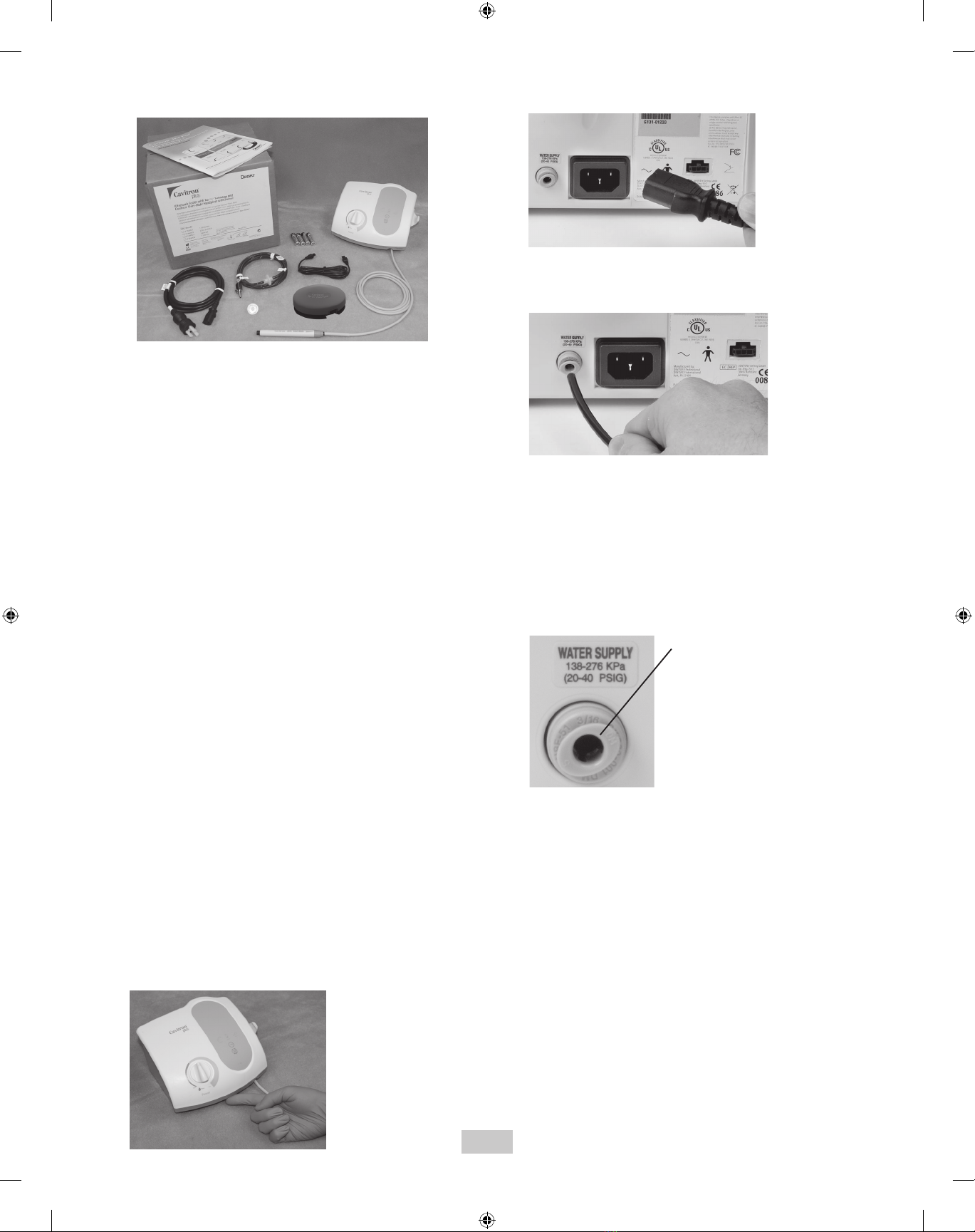
7.1 Water Line Requirements
• A water supply line with user-replaceable filter is
supplied with your system. See Section 10 System Care
for replacement instructions.
• Incoming water supply line pressure to the system must
be 20 psi (138 kPa) to 40 psi (275 kPa). If your dental
water system’s supply line pressure is above 40 psi,
install a water pressure regulator on the water supply line
to your Cavitron Plus Ultrasonic Scaler.
• A manual shut-off valve on the dental water system
supply line should be used so that the water can be
completely shut-off when the office is unoccupied.
• In addition to the water filter supplied, it is recommended
that a filter in the dental water system supply line be
installed so that any particulates in the water supply will
be trapped before reaching the Cavitron system.
• After the above installations are completed on the dental
water supply system, the dental office water line should
be thoroughly flushed prior to connection to the Cavitron
system.
• Incoming water temperature to the Cavitron System
should not exceed 25˚C (77˚F). If needed a device
should be installed to maintain a temperature within this
specification, or a Cavitron DualSelect Dispensing
System attached to allow this system to be operated
as a closed water system.
7.2 Electrical Requirements
• Incoming power to the system must be 100 volts AC to
240 volts AC, single phase 50/60 Hz capable of
supplying 1.0 amps.
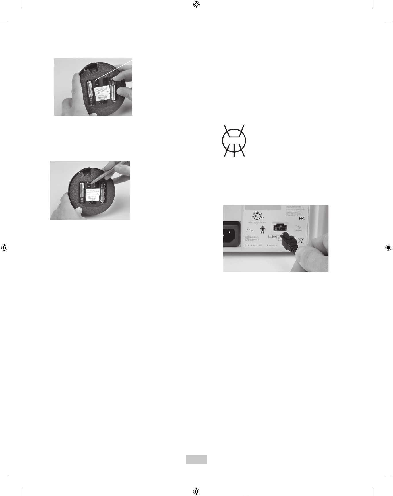
• The system power should be supplied through the AC
power cord provided with your system.
• WARNING:Toavoidriskofelectricshock,thisequipment
must only be connected to a supply mains with protective
earth.