CBS ArcSafe RRS-3 WL Owner's manual

Published and distributed by:
CBS ArcSafe®
2616 Sirius Road
Denton, Texas 76208
A division of:
GroupCBS, Inc.®
P.O. Box 1557
Gainesville, Texas 76241
Copyright CBS ArcSafe®2019
Printed in the United States of America
Reproduction, adaptation, or translation without prior written permission is prohibited except as is allowed by law.
RRS-3 WL
Installation and Operation
2616 Sirius Road |Denton, TX 76208 |(877) 4-SAFETY |www.cbsarcsafe.com
For Siemens WL Breakers
with Racking Rails
Rev. 2/19/2019
Distance
is
Safety
®
WE
DO.
WHAT STANDS
BETWEEN YOU AND
ARC-FLASH DANGER?

Published and distributed by:
CBS ArcSafe®
2616 Sirius Road
Denton, Texas 76208
A division of:
GroupCBS, Inc.®
P.O. Box 1557
Gainesville, Texas 76241
Copyright CBS ArcSafe®2019
Printed in the United States of America
Reproduction, adaptation, or translation without prior written permission is prohibited except as is allowed by law.
More Products by CBS ArcSafe®
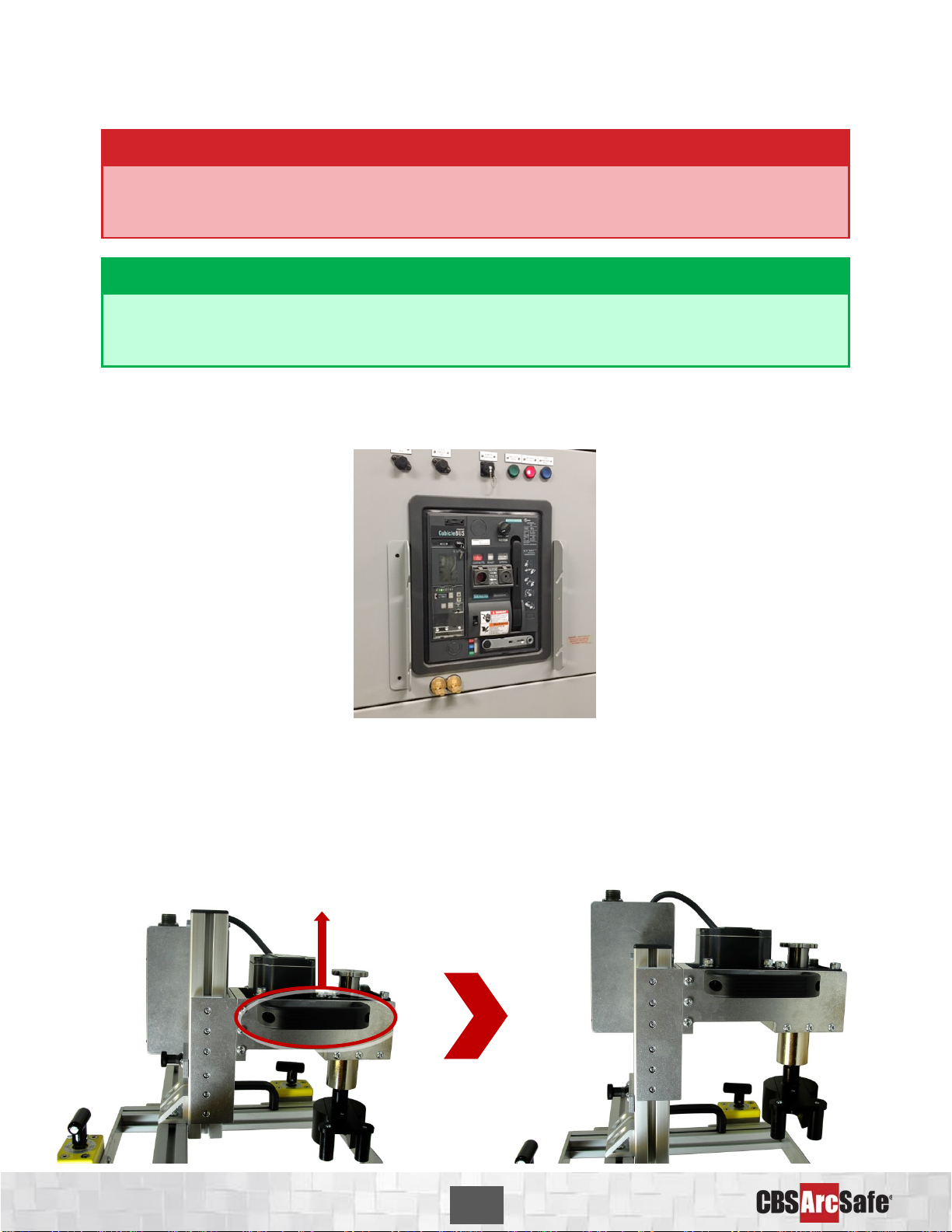
RRS-1 –Universal Remote Racking System (Rotary)
The CBS ArcSafe® RRS-1 is a universal remote racking system capable of remotely installing and removing rotary style draw
out circuit breakers without requiring any modification to the existing switchgear. Operation of the simple to use RRS-1 is
quite intuitive and requires only minimal setup. When used properly, the RRS-1 allows technicians to remain outside of the
arc flash boundary during the potentially dangerous racking operation.
RRS-2 –Universal Remote Racking System (Non-Rotary)
The CBS ArcSafe® RRS-2 is a universal remote racking system capable of remotely installing and removing non-rotary style
draw out circuit breakers without requiring any modification to the existing switchgear. Operation of the simple to use
RRS-2 is quite intuitive and requires only minimal setup. When used properly, the RRS-2 allows technicians to remain
outside of the arc flash boundary during the potentially hazardous racking operation.
RRS-3 –Application Specific Remote Racking System (Rotary And Non-Rotary)
The CBS ArcSafe® RRS-3 product line is made up of various application specific remote breaker racking devices. Each
standalone system allows service personnel to remotely install and remove a particular type of circuit breaker safely while
stationed safely outside of the arc flash boundary during the potentially dangerous operation. The lightweight and compact
design of the RRS-3 systems makes them ideal for hard to access areas where space is at a premium.
RRS-4 –PLC Based Universal Remote Racking System (Rotary)
The CBS ArcSafe® RRS-4 universal remote racking system is an updated PLC based version of the best selling RRS-1. The
dual mode, source programmable, PLC based control system offers two different operating modes to choose from based on
user preference or the application. The RRS-4 is capable of remotely installing and removing rotary style draw out circuit
breakers without requiring any modification to the existing switchgear, allowing users to remain outside of the arc flash
boundary during the potentially hazardous racking operation.
RSA –Remote Switch Actuator
The CBS ArcSafe® Remote Switch Actuator (RSA) product line is made up of various application specific remote operating
devices. These products allow service personnel to remotely perform all aspects of an operation for a particular type of
electrical equipment from outside the arc flash boundary – reducing or eliminating the possibility of serious injury or death
resulting from an arc flash.
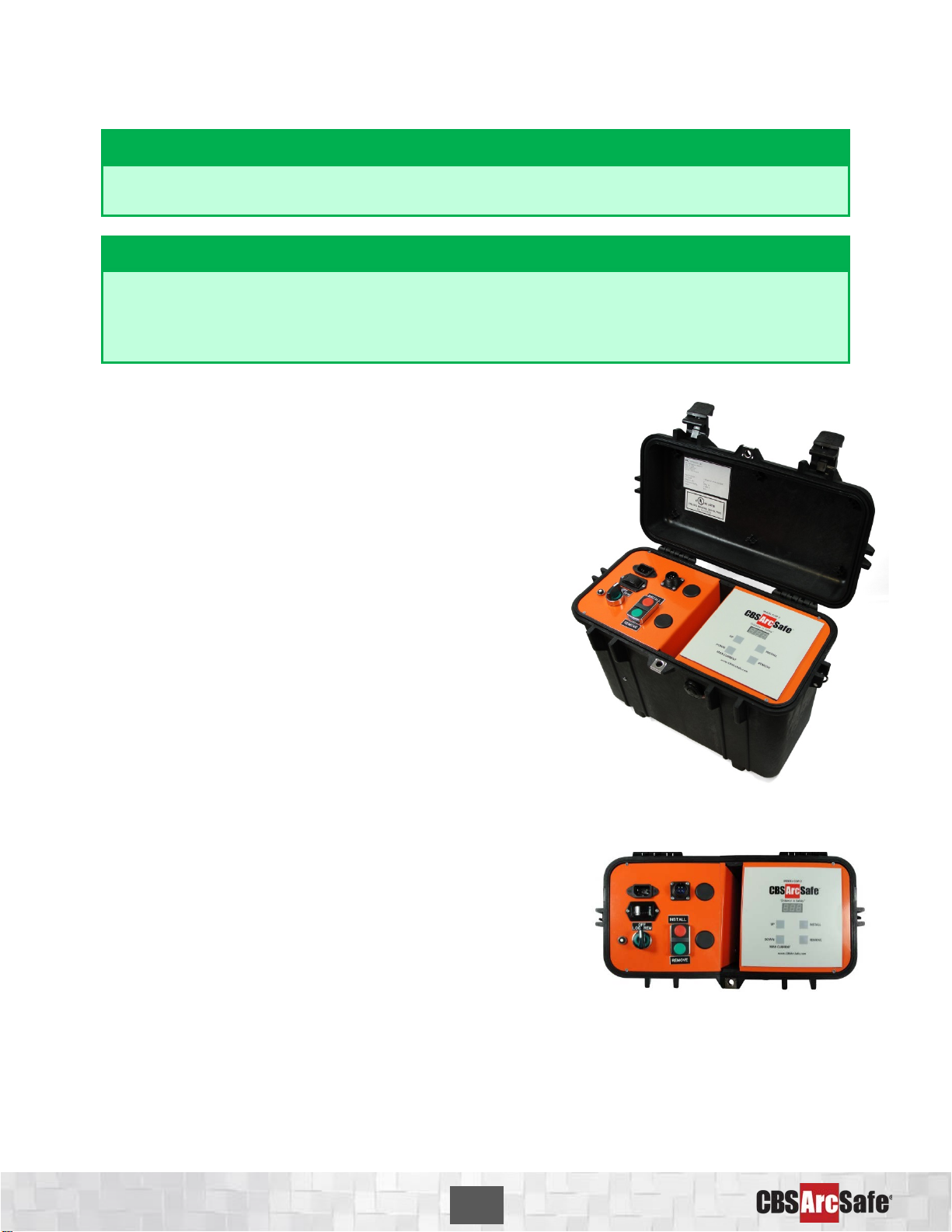
RSO –Remote Switch Operator
During a remote operation, the CBS ArcSafe® RSO functions as both the power supply and user interface for the device
being remotely operated by the user. When paired with an applicable CBS ArcSafe® device, this portable standalone
system allows service personnel to remotely perform a racking or switching procedure from outside the arc flash boundary
– reducing or eliminating the possibility of injury or death resulting from an arc flash

RRS-3 WL
Installation and Operation 1
About the User’s Guide
This user’s guide describes the functions and features of the CBS ArcSafe® Single Application Remote Racking
System (RRS-3). This technical document is intended to act as a simplified reference for users of the equip-
ment; allowing for safe, quick, and efficient use of the RRS-3 features.
DANGER!
This is a red hazard alert warning box; red hazard alert boxes contain information pointing
out potential hazards to personnel and equipment.
ATTENTION!
This is a green information box; green information boxes are used to place emphasis on valu-
able information the user will want to pay particular attention to.
DANGER!
Ensure that personnel using this equipment are adequately trained in the operation of the
switchgear they are planning to work with; that they are correctly stationed outside the arc
flash boundary; and that they comply with all applicable Federal, State, Local, and In-house
safety regulations and procedures. Attention should be given to distance, angle, and personal
protective equipment (PPE).
DANGER!
Ensure that switchgear is properly maintained and in good working order before using the
RRS-3 on your switchgear. Contact your local group CBS service provider at www.gcbs.com to
assist in proper care and maintenance for your switchgear.
2616 Sirius Road
Denton, TX 76208
Tel: 877-4-SAFETY
Fax: 940-382-9435
Website: www.CBSArcSafe.com
Email: [email protected]

RRS-3 WL
Installation and Operation 2
1Installation
DANGER!
Ensure that the equipment to be remotely operated matches the equipment shown and de-
scribed on the cover page. If the equipment does not match, please contact CBS ArcSafe® for
more information regarding remote operating applications for the equipment in question.
ATTENTION!
The location of certain items such as mimic bus, stickers, and/or placards may interfere with
the installation of the remote operating equipment. These items may need to be removed or
repositioned for proper installation.
1. Ensure that the breaker is free from any obstruction that may interfere with the proper installation of
the RRS-3.
2. Ensure that the torque limiter on the RRS-3 is set correctly to allow proper operation. See section 3.1
Torque Limiter in this manual for more details
3. Retract the slide assembly fully back by placing the RRS-3 face-down, gripping the handles mounted
to each side of the motor, and pulling up until the black locking pin clicks into place.

RRS-3 WL
Installation and Operation 3
4. Place the RRS-3 on the breaker faceplate, and ensure that the locators around the RRS-3 are flush
with the upper edge and sides of the breaker, as shown below.
5. Secure the RRS-3 to the breaker by turning the handles of the twist magnets 180 degrees clockwise.
6. Extract the racking handle from the WL breaker, and pull it out fully until it clicks and locks into place.
Ensure that the handle extension is pulled fully out as shown below.
7. Pull upwards on the black locking pin until the slide assembly is released. When released, the slide
assembly will gently slide forward on its own.

RRS-3 WL
Installation and Operation 4
8. Ensure that the breaker’s racking handle fits properly into the racking operator on the RRS-3, as
shown. If it does not align, slowly rotate the adapter on the RRS-3 until it aligns properly with the
handle.
The RRS-3 is now ready for operation.

RRS-3 WL
Installation and Operation 5
2Operation
ATTENTION!
Please ensure that all cables are clear of moving parts. Failure to do so may result in damage
to cables and/or actuator.
ATTENTION!
Please ensure that the batteries to the RSO-IV are fully charged or that the unit is plugged into
AC power.
For detailed instructions on the operation of the RSO-IV please see the RSO-IV Manual.
1. Ensure that the RRS-3 is properly installed. See the In-
stallation section of this manual for detailed instruc-
tions.
2. Connect the cable from the RSO-IV to the motor control
box on the RRS-3
3. Turn the power switch on the RSO-IV to the ON position.
4. Program the settings for the RRS-3 into the RSO-IV.
These settings can be found on the placard on the RRS-
3. For more information on programming the RSO-IV
please refer to the RSO-IV Technical Manual.
5. Exit the arc flash boundary.
6. Once the current limits have been properly set, press
and release the REMOVE button on the RSO-IV control
panel or remote pendant to rack the breaker out.
7. Press and release the INSTALL button on the RSO-IV
control panel or remote pendant to rack the breaker in.

RRS-3 WL
Installation and Operation 6
3Adjustments
3.1
Torque Limiter
The torque limiter is designed as the primary safety system to reduce the possibility of damaging the circuit
breaker racking mechanism with the RRS-3. The torque limiter attaches to the drive coupling and mates with
the racking tool. The torque limiter is set from the factory for your particular breaker, so only adjust as
needed for your specific situation. Note: A ½ inch drive torque wrench will be required to perform this adjust-
ment.
1. First, remove the racking tool adapter from the RRS-3 by pushing in the locking pin at the base of the
adapter, as shown. The racking adapter can then be fitted to a standard ½ inch drive torque wrench.
2. On the de-energized and OPEN test breaker, extract the breaker’s racking handle, and fit the racking
adapter to the handle as shown in the Installation section of this manual.
3. To determine the proper torque required to rack the breaker, first rack the breaker out, measuring
the maximum amount of torque needed. Record this value.

RRS-3 WL
Installation and Operation 7
ATTENTION!
When the breaker reaches either the test or disconnected position the torque will rise as vari-
ous interlocks and mechanical limits engage. Do NOT apply any torque to the racking mecha-
nism greater than that seen during the racking process.
4. Next, reset the torque wrench (if needed) and proceed to rack the breaker in, again measuring the
maximum torque applied. Record this value.
ATTENTION!
As you begin racking the breaker onto the stabs the torque should raise, and then almost
immediately after the breaker is on the stabs the torque will lower and then spike as you hit
the racking limits. This spike is the breaker starting to be racked in too far. DO NOT continue
to rack in the breaker at this point. The maximum amount of force the breaker needs to rack
will be found as breaker has gone onto the stabs
DANGER!
As breakers age and/or do not see regular maintenance the torque needed to rack a breaker
may increase. However, large increases of torque needed to rack a breaker including amounts
over 10% of the average torque may indicate breaker problems, which could lead to an arc
flash.
If the RRS does not seem to have enough torque, first double check that the breaker is operat-
ing properly before racking out by hand.
5. Take the the higher of the two recorded values and multiply by 1.1. This adds an additional 10%
margin of error for the torque limiter. This new value is the setting for the torque limiter.
6. Next, Attach the torque wrench to the spring loaded drive head (Various different socket adapters
may be necessary depending on the drive size of the torque wrench) and use the torque wrench to
determine the present setting of the torque limiter. The torque limiter body will need to be held still
during this operation.
7. Remove the snap ring and locking plate from the torque limiter.
8. Adjust the nut clockwise to increase torque, and counter-clockwise to decrease torque.
9. Obtain a new torque reading with the torque wrench to verify the new torque setting. Repeat steps
8-9 until the torque value determined in step 5 is reached.
10. Replace the locking plate and snap ring onto the torque limiter.
DANGER!
Inaccurate setting of the torque limiter may result in excessive slip during racking operations
or, if over-tightened, the remote rack placing excessive torque on the breaker racking mecha-
nism; possibly leading to equipment damage.

RRS-3 WL
Installation and Operation 8
3.2
Actuator Location Adjustment
In order to adjust the horizontal and vertical location of the actuator and slide assembly on the RRS-3,
several adjustment points are given on the frame. The RRS-3 comes pre-adjusted from the factory for it’s
breaker, so these adjustments should not normally need to be made.
To adjust the vertical positioning of the slide assembly:
1. Loosen the four bolts on the side L-brackets as indicated below.
2. Next, move the assembly up or down as required to align the RRS-3 racking adapter with the breaker
racking handle.
3. Re-tighten the bolts loosened previously.

RRS-3 WL
Installation and Operation 9
To adjust horizontal positioning of the slide assembly:
1. Loosen the two bolts on the angle brackets above the slide assembly as shown.
2. Next, move the assembly left or right as required.
3. Re-tighten the bolts loosened previously.


RRS-3 WL
Installation and Operation 11
Notes

RRS-3 WL
Installation and Operation 12


RRS-3 WL
Installation and Operation
DANGER!
Ensure that personnel using this equipment are adequately trained in the operation of the
switchgear they are planning to work with; that they are correctly stationed outside the arc
flash boundary; and that they comply with all applicable Federal, State, Local, and In-house
safety regulations and procedures. Attention should be given to distance, angle, and person-
al protective equipment (PPE).
2616 Sirius Road
Denton, TX 76208
Tel: 877-4-SAFETY
Fax: 940-382-9435
Website: www.CBSArcSafe.com
Table of contents
Other CBS ArcSafe Industrial Equipment manuals