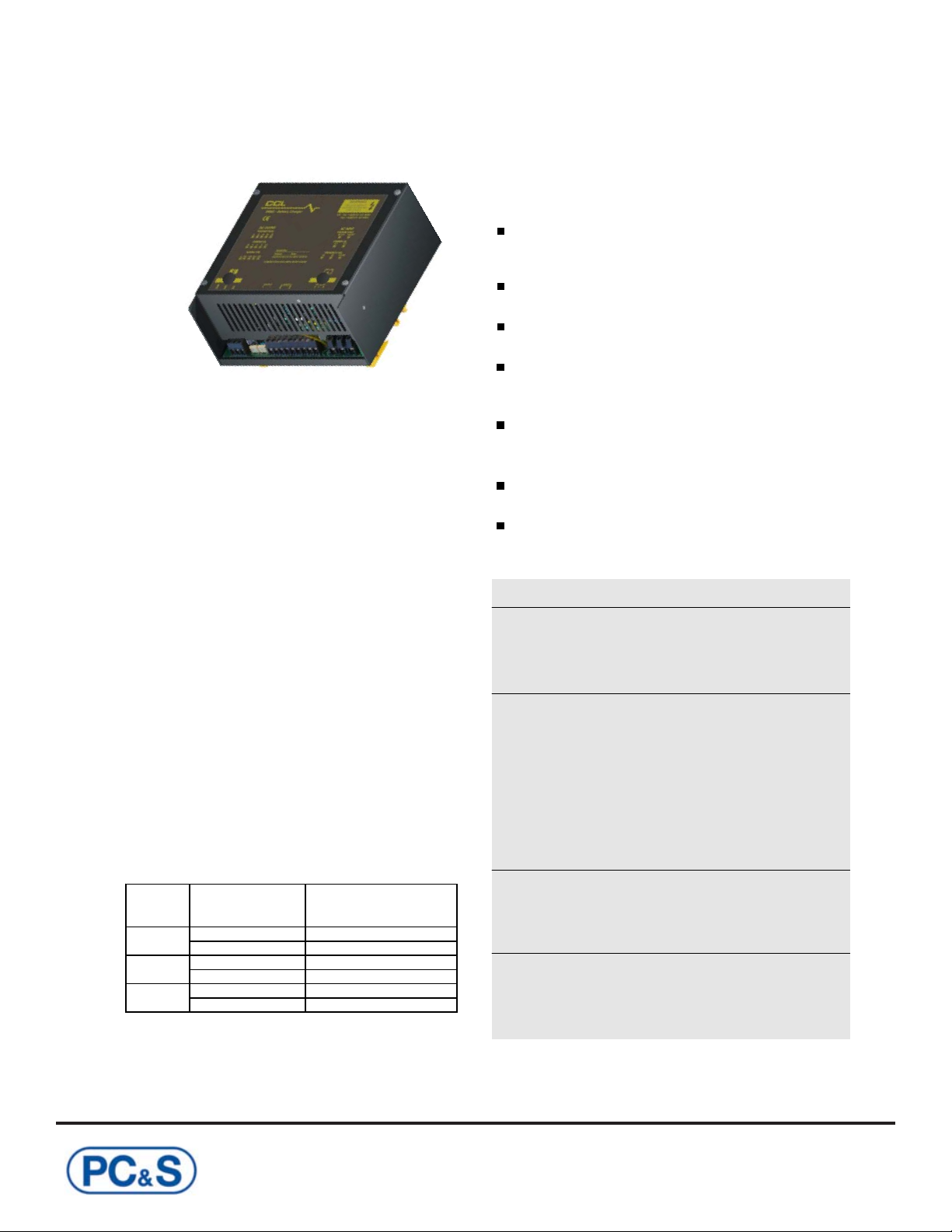
SM82ASwitchmode Range of Battery Chargers
Connections & Controls
How to Use
Table (B) -Typical charging characteristics
Ensure correct AC Input Voltage input is selected on the charger (9)
If using the 6/12V switchable model, ensure the 6/12V Voltage Selector (8) is configured correctly, (ON for 12V, OFF for 6V)
Connect AC supply to terminals (2) observing connection details, and plug into the mains, switch the mains on and check the battery charged (float) LED (4)
illuminates (if connected), then switch off at mains.
Ensure that the battery pack is either Vented or VRLA (sealed) rechargeable lead acid only. Confirm the correct charging stage to be used from Table (A) on
page 1 and connect mode selector jumper (7) to suit as described above.
Connect the +Ve and -Ve terminals (4) to battery/battery pack
IMPORTANT: CHECK POLARITY OF BATTERY
CONNECTIONS REVERSE POLARITY WILL DAMAGE
BATTERIES
In Auto-3 Stage Mode of Operation (with LED’s Connected):
Switch on at mains, ‘Boost’ LED (4) should now be
illuminated. When the battery pack is fully charged the ‘Float’
LED (4) should be illuminated and the ‘Boost’ LED (4) should
switch off. Once fully charged the battery packs will receive a
float charge at specified voltage on Page 1, keeping batteries
in prime condition ready for use.
Before disconnecting the battery pack from charger, switch of
at mains, disconnect battery pack and then disconnect
charging leads from charger.
In Float Mode of Operation:
As above, only the Float LED (4) will be permanently
illuminated.
Notes: If no AC is present and the unit is connected to a
battery, then the C/F LED (2) will be illuminated. The SM82A
charger draws 20mA from battery(s) when connected with no
AC present. With AC present and no battery/load connected
the Float LED (2) will also be illuminated. All the LED outputs
are configured for 2.5VDC LED’s, no voltage drop down
resistor is required.
When using the charger in the Auto 3 Stage mode, either
neither of LED’s should be connected or both the Float and
Boost LED’s must be connected for them to function
correctly, if only 1 of the LED’s are connected they will not
function correctly.
ENSURE CONNECTION OF LED’S IS CORRECT
BEFORE SWITCHING ON UNIT - INCORRECT
CONNECTION MAY DAMAGE THE CHARGERS LED
OUTPUT CONTROLLER
Charge Fail / Loss of AC
Supply Relay Output
(1)
Note: The SM82A may be fitted with an on-board LED
(marked LED1), this is an internal LED to indicate charger
control circuit is operational and used for internal test
purposes only. Not all units have this device fitted.
LED1
(See notes right)
Notes on Charging mode selector and boost operation:
With both the charging stage mode selector jumpers fitted
uppermost (M) on (7), the unit will function in the float mode,
providing a constant voltage output (at specified level as
shown on page 1), an increased ‘boost’ voltage can be
manually triggered by linking the Boost Terminals (4). Fitting
both jumpers towards (A) on (7) will put the charger in Auto-
3 Stage mode.
Note: Care should be taken when using the manual boost
mode so overcharge does not take place, the boost link
should be timed or monitored until battery voltage reaches
required level.
WARNING! Continuous boost charging will damage the
batteries
Factory default units are shipped with Jumper (7) fitted
in M position for Float mode, Jumper (8) fitted for 12V
setting (on 6/12V units) and Jumper (9) selected for
240VAC.
BATTERY VOLTAGE
CHARGING CURRENT
AS CHARGER SWITCHES
FROM BOOST TO FLOAT
THE BATTERY NEEDS A
SMALL PERIOD OF TIME
TO SETTLE. DURING THIS
PHASE NO CURRENT WILL
FLOW FROM CHARGER.
FLOAT CURRENT
AT BATTERIES
KNEE POINT CURRENT
STARTS TO FALL
VOLTAGE / CURRENT
FLOAT STAGE
BOOST STAGE
Auto 3 Stage Mode
CONSTANT CURRENT
(CURRENT LIMITED)
BATTERY VOLTAGE
CONSTANT VOLTAGE
(FLOAT STAGE)
CHARGING CURRENT
FLOAT CURRENT
AT BATTERIES
KNEE POINT CURRENT
STARTS TO FALL
TIME
VOLTAGE / CURRENT
Float Mode
(80% CHARGED)