IES Keywatt 24 User manual

User Manual
Keywa 24 Staon
www.ies-synergy.com
DUM3017446-EN_V001b

www.ies-synergy.com
User Manual DUM3017446-EN
2
The information provided in this documentation contains general descriptions and/or technical characteristics
of the performance of the products contained herein. This documentation is not intended as a substitute for
and is not to be used for determining suitability or reliability of these products for specific user applications. It
is the duty of any such user or integrator to perform the appropriate and complete risk analysis, evaluation and
testing of the products with respect to the relevant specific application or use thereof. Neither IES Synergy nor
any of its affiliates or subsidiaries shall be responsible or liable for misuse of the information contained herein.
If you have any suggestions for improvements or amendments or have found errors in this publication, please
notify us.
You agree not to reproduce, other than for your own personal, noncommercial use, all or part of this document
on any medium whatsoever without permission of IES Synergy, given in writing. You also agree not to establish
any hypertext links to this document or its content. IES Synergy does not grant any right or license for the per-
sonal and noncommercial use of the document or its content, except for a non-exclusive license to consult it on
an “as is” basis, at your own risk. All other rights are reserved.
All pertinent state, regional, and local safety regulations must be observed when installing and using this prod-
uct. For reasons of safety and to help ensure compliance with documented system data, only the manufacturer
should perform repairs to components.
When devices are used for applications with technical safety requirements, the relevant instructions must be
followed.
Failure to use IES Synergy software or approved software with our hardware products may result in injury,
harm, or improper operating results.
Failure to observe this information can result in injury or equipment damage.
© 2020 IES Synergy. All rights reserved.

www.ies-synergy.com
User Manual DUM3017446-EN
3
Table of content
1. Safety notes 4
Notice 4
Please note 4
2. About the manual 5
Purpose of this manual 5
Document scope 5
Related documents 5
User comments 5
3. General safety instructions 6
4. Overview 7
External view 7
5. Specification 8
Main supply 8
Technical specifications 8
6. Utilization 12
Human/Machine interface (HMI) and LEDs 12
Prerequisite 13
Start an EV charge session 13
EV charge 15
Stop an EV charge session 16
Emergency Stop 18
Errors 20

www.ies-synergy.com
User Manual DUM3017446-EN
4
1. Safety notes
Notice
Read these instructions carefully, and look at the equipment to become familiar with the device before trying
to install, operate, or maintain it. The following special messages may appear throughout this documentation
or on the equipment to warn of potential hazards or to call attention to information that clarifies or simplifies
a procedure.
The addition of this symbol to a Danger hazard statements indicates that an electrical hazard
exists, wich result in personal injury if the instructions are not followed.
This is the safety alert symbol. It is used to alert you to potential personnal injury hazards. Obey
all safety messages that follow this symbol to avoid possible injury or death.
IDANGER
DANGER indicates an imminently hazardous situation which, if not avoided, will result in death or seri-
ous injury.
IWARNING
WARNING indicates a potentially hazardous situation which, if not avoided, can result in death or seri-
ous injury.
ICAUTION
CAUTION indicates a potentially hazardous situation which, if not avoided, can result in minor or mod-
erate injury.
NOTICE
NOTICE is used to address practices not related to physical injury.
Please note
IES Synergy declines all responsibility for improper use of this equipment.
Technical documentation is an integral part of a product. Until it is disposed of, always keep the technical docu-
mentation close to the unit at hand, as it contains important information. Provide technical documentation to
the person concerned if you sell, assign or lend the product.

www.ies-synergy.com
User Manual DUM3017446-EN
5
2. About the manual
Purpose of this manual
This guide describes how to use the Keywatt 24 Station.
Document scope
This guide concerns the following charging stations:
• P/N: ST24 TRI 3PN CHARGER
Related documents
Document title Product Reference
Installation Manual ST24 DIM3017446-EN
User Manual ST24 DUM3017446-EN
Service Manual ST24 DMM3017446-EN
User comments
We invite you to write to us to communicate any inaccuracies or omissions, or to make general comments or
suggestions regarding the quality of this manual.

www.ies-synergy.com
User Manual DUM3017446-EN
6
3. General safety instructions
NOTICE
SAVE THESE INSTRUCTIONS
• To ensure proper and safe operation, please read these user instructions carefully and
keep them for future reference.
• This manual contains important instructions for KEYWATT 24 STATION that shall be
followed during installation, operation and maintenance of the unit.
• The locking key, supplied with unit, should be kept in a secure and known location by an
individual that has read and understands the content of this manual.
IWARNING
RISK OF ELECTRIC SHOCK, INJURY, AND/OR BURNING
• Only qualified, trained and authorized people will repair, replace or adjust this equipment.
• Make sure the AC input breaker is OFF and measures 0V after the breaker.
• Do not use this product if the cables (input or output) are frayed, have damaged insulation
or any other signs of damage.
• Do not use this product if the enclosure or the EV connectors are broken, cracked, opened
or show any other indication of damage.
• This equipment employs parts (switches and relays), that tend to produce arcs or sparks.
• Never open the charger while input power is present.
Failure to follow these instructions can result in death or serious injury
ICAUTION
RISQUE DE DOMMAGE AU MATÉRIEL
• Do not use this product if the cables (input or output) are frayed, have damaged insulation
or any other signs of damage.
• Do not use this product if the enclosure or the Electrical Vehicle Supply Equipment (EVSE)
connectors are broken, cracked, opened or shows any other indication of damage.
• Do not use a cord extension set or second cable assembly in addition to the cable assembly
for the connection of the EV to the EVSE.
Failure to follow these instructions may result in serious injury or equipment damage.
www.ies-synergy.com
User Manual DUM3017446-EN
7
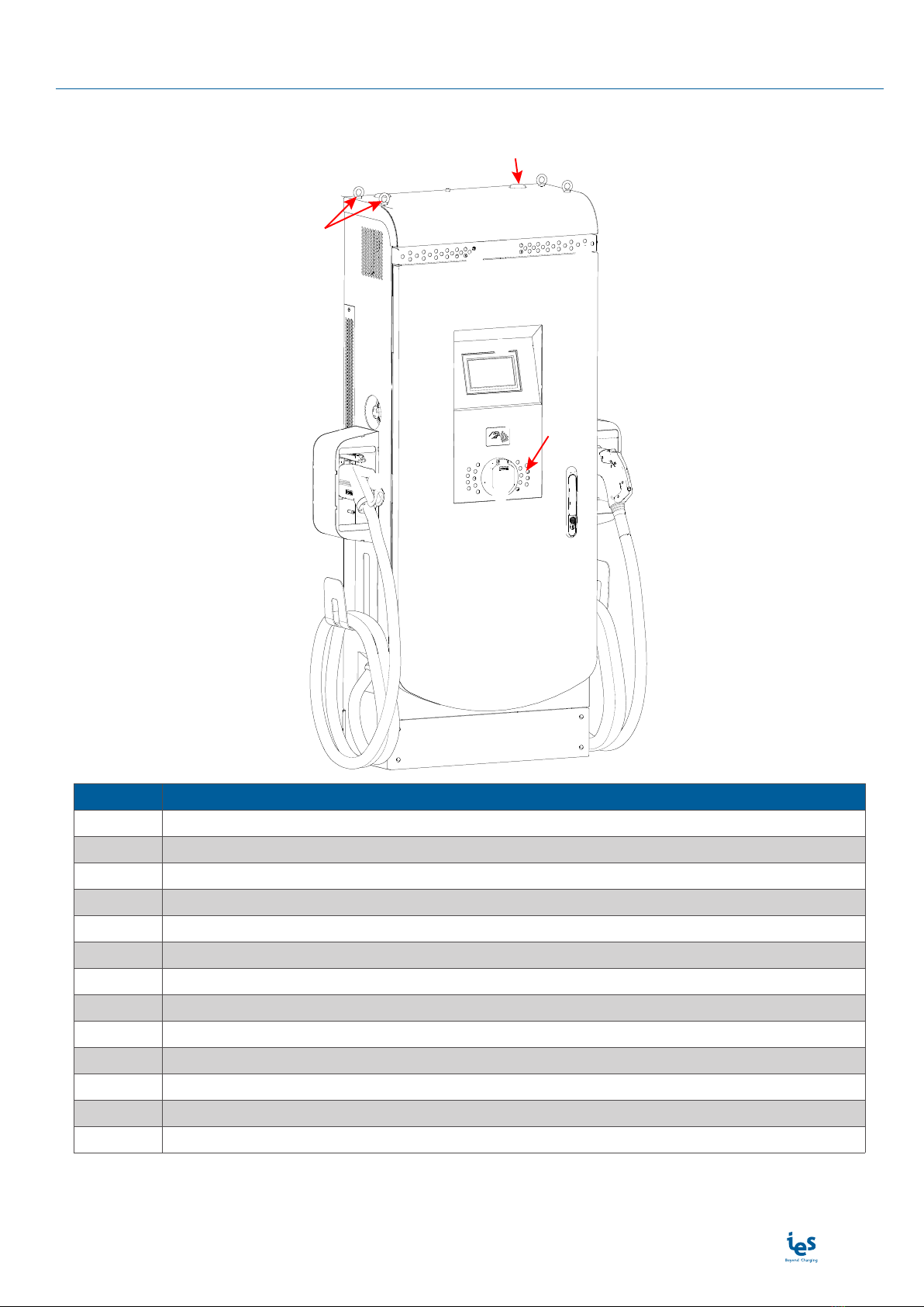
4. Overview
External view
❶
❷
❹
❽
❾
❸
❺⓫⓬
⓭
❿
❻❼
Position Description
1 Antenna (x2)
2Liing rings (x4)
3 Emergency Stop button
4 Connector support (x2)
5 CCS Type 2 DC connector
6 COMBO 2 LED
7 CHAdeMO LED
8 Touchscreen display
9 RFID reader
10 Type 2S AC outlet LED
11 AC socket outlet Type 2 S
12 CHAdeMO DC connector
13 Key lock
Note: May change depending on version or technical modification

www.ies-synergy.com
User Manual DUM3017446-EN
8
5. Specification
Main supply
Mains supply 3-phase L1/L2/L3+ N + PE
DC charger input
Mains 3-phase voltage range (phase to phase) VAC 400 VAC ± 10%
Earthed electrical system TT; TN
Frequency range f 50 Hz ± 10%
Nominal input current IAC 38A Nom
Maximum input current IAC 42A Max
Power Factor PF 0,99 Nom
Efficiency ɳ95 % Max
Harmonic current @ nominal network voltage THDi < 13 % Max
AC charger input
Mains 3-phase voltage range (phase to phase) VAC 400 VAC ± 10%
Earthed electrical system TT; TN
Frequency range f 50 Hz ± 10%
Nominal input current IAC 32A Nom
Maximum input current IAC 35A Max
Technical specifications
DC charger internal AC input protection
Inrush current limitation per phase IAPPEL LIMITE < 3 x IAC Max
Rated Current Fuse (per module) ICOUPURE Nominal 80A typ
Breaking capacity of fuses ICOUPURE Capacité 80 000A Max
Max earth leakage current IFUITE < 5 mA Max
Overvoltage category (IEC60664-1) III
Charger short-circuit current resistance ICC 6 kA Max
Internal DC Output
COMBO 2 output voltage VDC_max 530 VDC Max
VDC_min 200 VDC Min
CHAdeMO output voltage VDC_max 500 VDC Max
VDC_min 150 VDC Min
Output current IDC_max 65A (1)(2) Max
IDC_min 1,5A Min
Max Output Power POUT 24kW Max
Output connector (charging station side) Permanent mounting
Car Plug connector Plug #1 COMBO 2
Plug #2 CHAdeMO
Output cable length - 5 Meters
Internal DC output protection
Hardware and software short circuit protection Oui
Software and Hardware over voltage protection adjustable +10% max

www.ies-synergy.com
User Manual DUM3017446-EN
9
Internal DC output protection
Over temperature protection - 70 °C
Reverse polarity protection Yes
DC output Contactor Yes (2 pôles)
Rated Current Fuse (output) IFUSE 125 A
Max time for DC line discharge < 60V T<60V 1 s
AC output
AC Output voltage VAC_nom 400 VAC ± 10%
AC Output current IAC_max 32 A Nom
Max Output Power POUT 22 kVA Max
Car Plug socket Plug #3 AC type 2 S
Type of connection Detachable cable
Internal AC output protection
Inrush current 230A during 100 µs
Short circuit Socket I²t A²s 75 000
Circuit breaker for AC circuit 50A curve C
Embedded Insulation device of charger module
Response time (tan) < 3sec. for asymmetrical fault
< 62sec. for symmetrical fault
Self test time At power on and every 60s during charge
Measurement method Continuous and switching measurement resistor method
Fault trigger threshold (CCS, CHAdeMO and
GB before the charge only) 100 Ω/V ± 10%
Warning detection threshold (CCS only) 500 Ω/V ± 10%
System leakage capacity Ce ≤ 1µF : response value (Ran) and time (tan) are not guar-
anteed for capacity above 1µF
Radio Frequency characteristics
The equipment module is designed to provide customers with global network coverage on the connec-
tivity of UMTS/HSPA+, and it is also fully backward compatible with the existing EDGE and GSM/GPRS
networks.
Output power (dBm)
Class 4 (33dBm±2dB) for GSM850 and EGSM900
Class 1 (30dBm±2dB) for DCS1800 and PCS1900
Class E2 (27dBm±3dB) for GSM850 and EGSM900 8-PSK
Class E2 (26dBm+3/-4dB) for DCS1800 and PCS1900 8-PSK
Class 3 (24dBm+1/-3dB) for UMTS800/850/900/1900/2100
General & dimensions
External dimensions (without support) (mm) H x W x D 1750 x 700 x 356 mm
External dimensions (with support) (mm) H x W x D 1758 x 1000 x 396 mm
Weight (without cable and connector) kg 200 kg Max
Type of installation Fastening to concrete slab with suitable fas-
tening points
Fixation points 4 goujons M14 (non fournis)
Mechanical impact resistance (not the screen) IK IK10
Protection type (EN60529) IP IP55

www.ies-synergy.com
User Manual DUM3017446-EN
10
General & dimensions
Cooling systems Heatsink with forced air flow by fans IP55
without air filter
Noise (1m) dB(A) 56dBA (1m)
Noise (5m) dB(A) 41dBA (5m)
Climatic & Environment constraints
Operating temperature (with derating) -25°C to +55°C(2)
Storage temperature -25°C to +70°C
Relative humidity RH 10% to 95%
Installation altitude Alt 2 000m Max
Norms & standards
Radio Equipment Directive (RED) 2014/53/EU
Efficient use of Radio Spectrum (RED)
ETSI EN 301 511 V12.5.1
ETSI EN 301 908-1 & -2 V11.1.1
ETSI EN 300 330 v2.1.1
Electric vehicle conductive charging system –
Part 1: General requirement IEC 61851-1
Electric vehicle conductive charging system –
Part 23: DC Electric vehicle charging station IEC 61851-23
Information technology equipment –Safety –
Part 1: General requirements EN 60950-1:2006 (A1, A2, A11, A12)
Information technology equipment –Safety –
Part 22: Equipment to be installed outdoors EN 60950-22:2006
Electric vehicle conductive charging system –
Part 22: AC electric vehicle charging station EN 61851-22:2002
Electric vehicle conductive charging system –
Part 24: Digital communication between a DC EV charging station
and an electric vehicle for control of DC charging
EN 61851-24
Electric vehicle conductive charging system –
Part 21-2: Electric vehicle requirements for conductive connection
to an AC/DC supply - EMC requirements for off board electric vehi-
cle charging systems
IEC 61851-21-2
Insulation Monitor Device (IMD) IEC 61557-1 & IEC 61557-8
RoHS 2015/863/EU
Declaration of conformity CE(3) Yes
(1) Max output current will be adapted versus maximum carrying current of the vehicle plug.
(2) The output current is reduced as a function of the temperature above 40°C..
(3) CE marking affixed on the product attest the conformity of the product with applicable requirements of relevent Community har-
monization legislation.
www.ies-synergy.com
User Manual DUM3017446-EN
11
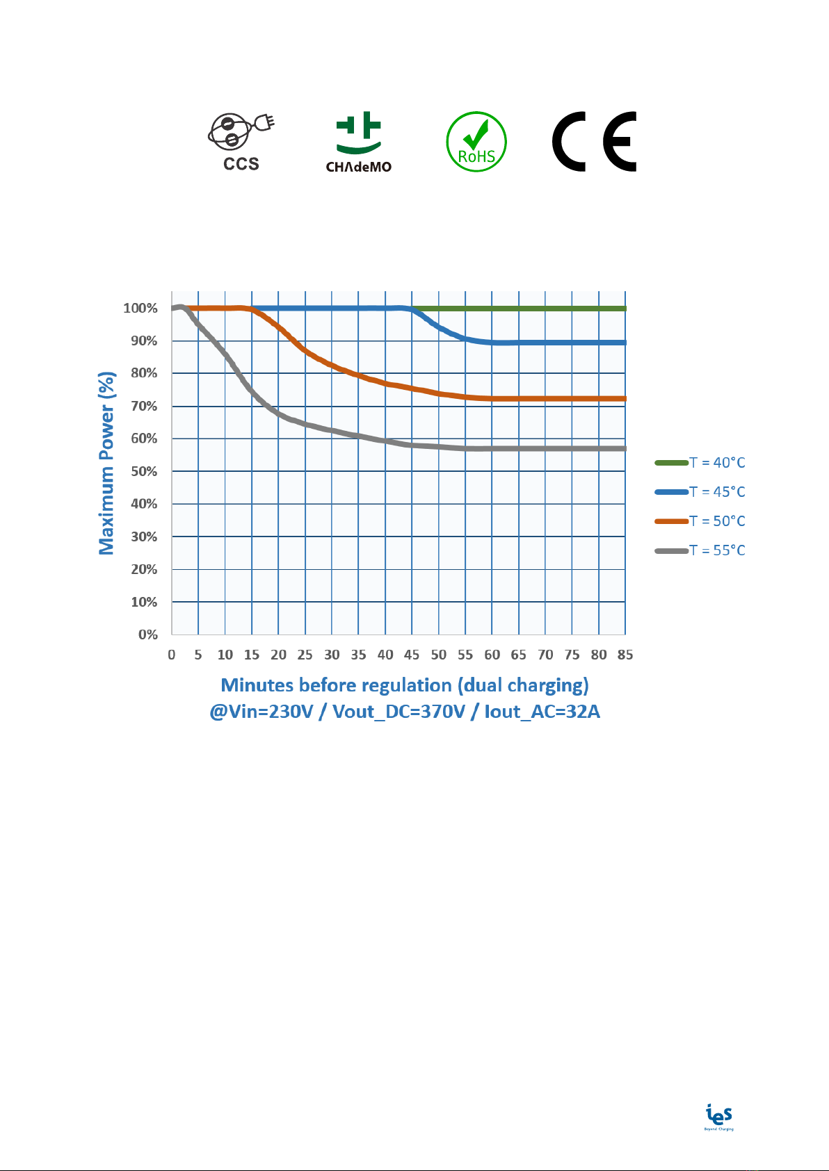
Compliance
Derating
There is a direct correlation between the current delivered and the ambient temperature. The output power is
determined by the power vs. temperature derating curve below :

www.ies-synergy.com
User Manual DUM3017446-EN
12
6. Utilization
Human/Machine interface (HMI) and LEDs
CCS, AC and CHAdeMO
available
CCS and AC plugged
CHAdeMO unavailable
Communicating with
the EV
CCS and AC
simultaneously charging
CHAdeMO unavailable
End of CCS and AC charge
Cables connected
AC error detected
Dual charging disabled
OFF OFF OFF OFFOFF
Note: Applicable in COMBO, CHAdeMO and AC.
www.ies-synergy.com
User Manual DUM3017446-EN
13
Prerequisite
Before starting a charge:
Make sure that the unit is mounted according to the installation instructions before using it.
You must have an RFID card activated on the supervision server (backend) or be connected to the supervision
tool.
Note: The MIFARE 1k RFID card is recommended.
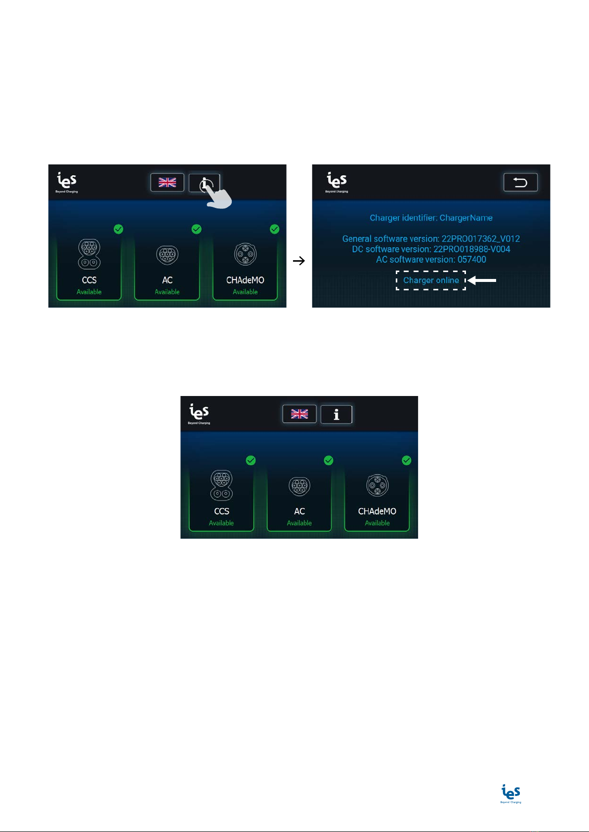
To check that the charging station is connected to the supervision tool:
BIP
If the charging station is not connected to the supervision server, please refer to the maintenance manual.
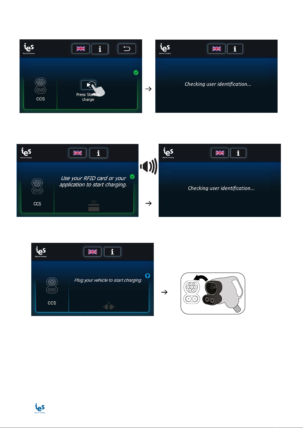
Start an EV charge session
1) Select the type of charge
www.ies-synergy.com
User Manual DUM3017446-EN
14
2) User identification
Press “Start” (free-use mode) or swipe an activated RFID card or start the charge remotely via a supervision
application
BIP
Note: Applicable in COMBO, CHAdeMO and AC
or
BIP
Note: Applicable in COMBO, CHAdeMO and AC
3) EV connection
BIP
Note: Applicable in COMBO, CHAdeMO and AC
www.ies-synergy.com
User Manual DUM3017446-EN
15
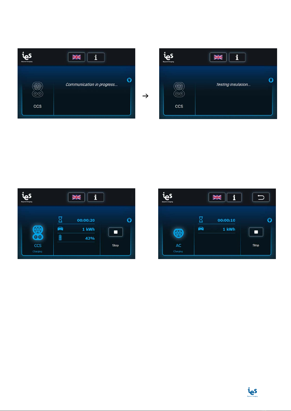
4) EV communication
This step is necessary to adapt the charger parameters to the EV.
Observe the display; charging will begin once communication has been established between the charger and
the EV.
BIP
Note: Applicable in COMBO, CHAdeMO and AC Note: Applicable in COMBO and CHAdeMO
EV charge
Only one DC connector and one AC connector can be used under simultaneous charge.
The charging station displays the:
• time since the start of charging
• charged energy
• percentage of charge (not in AC)
Note: Applicable in COMBO and CHAdeMO Note: Applicable in AC
The charger will automatically stop once charging is completed. Fast charging will occur up to 80% of the
vehicle battery state of charge. The charger will adjust its output according to the demands of the vehicle,
ambient temperature and other factors.
After completing the charge of the EV, the charging station performs multiple control steps before disconnect-
ing the vehicle.
www.ies-synergy.com
User Manual DUM3017446-EN
16
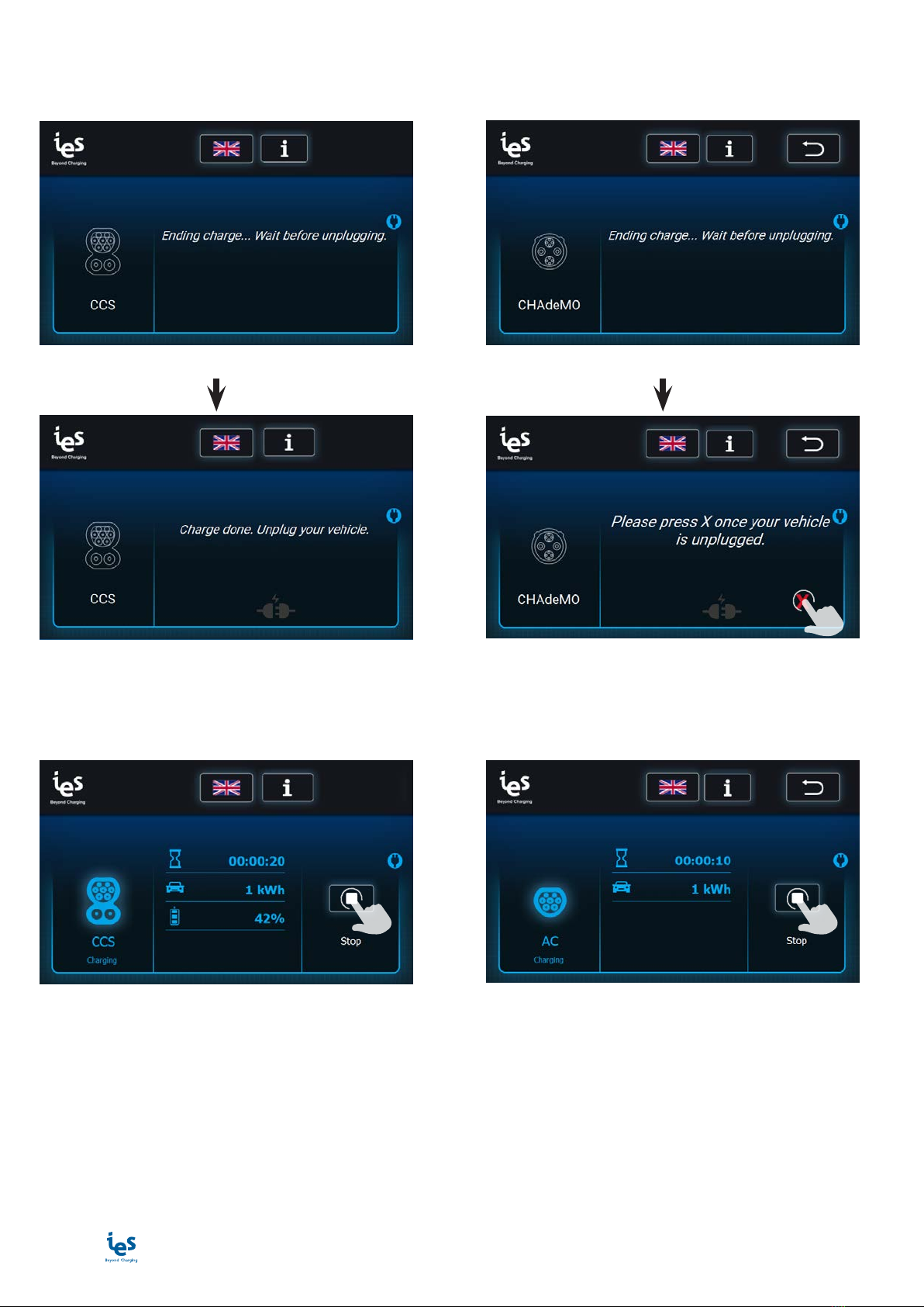
COMBO and AC CHAdeMO
Unplug the EV once the charge is done . Press Xonce the EV is unplugged.
Note: Applicable in COMBO and AC Note: Applicable in CHAdeMO
Note: Applicable in COMBO and AC Note: Applicable in CHAdeMO
Stop an EV charge session
To stop the charge before the end of the EV charge:
Note: Applicable in COMBO and CHAdeMO Note: Applicable in AC

www.ies-synergy.com
User Manual DUM3017446-EN
17
A) Swipe the RFID card used to launch the charge in front of the RFID reader
or
B) Stop the charge remotely via a supervision application or directly on the screen
Note: Applicable in COMBO, CHAdeMO and AC
The screen displays that the session is ending:
COMBO and AC CHAdeMO
Unplug the EV once the charge is done . Press Xonce the EV is unplugged.
Note: Applicable in COMBO and AC Note: Applicable in CHAdeMO
Note: Applicable in COMBO and AC Note: Applicable in CHAdeMO

www.ies-synergy.com
User Manual DUM3017446-EN
18
Emergency Stop
In the event of an emergency the Emergency Stop button may be pressed to instantly stop charging.
To emergency stop follow these steps:
❷
❶
BIP
❸
To reset after an emergency stop, rotate the button clockwise until it pops outward. After a self-test, the display
will remove the emergency stop message and will be ready for a new session.
www.ies-synergy.com
User Manual DUM3017446-EN
19
Other messages
Message Description
Error connecting server.
Booting interrupted !
Please call support.
Message displayed during the startup of the
charging station if the backend server reject the
connection.
Error connecting to RFID reader.
Booting interrupted !
Please call support.
Message displayed during the startup of the
charging station if the RFID module does not work.
Please contact support.
Error connecting to Communication Control Unit.
Booting interrupted !
Please call support.
Message displayed during the startup of the
charging station if the CCU board does not work.
Please contact support.
Error connecting to AC Unit.
Booting interrupted !
Please call support.
Message displayed during the startup of the
charging station if the AC powershare board does
not work. Please contact support.
AC contactor failed.
Please unplug any connected vehicle and call sup-
port.
Message displayed during the startup of the
charging station if the AC powershare board does
not work. Please contact support.
Charger inoperative. Cannot charge here. Charger inoperative. Backend server request char-
ger does not accept charge
Charger inoperative. Please unplug your vehicle. Charger inoperative. Backend server request char-
ger does not accept charge. Unplug the vehicle.
Authorization failed!
Please retry identifying.
User rejected by the backend server.
Charger offline. Set up to refuse offline charging. Charger offline.
Error timeout. Please unplug your vehicle then
identify.
Time out, user identified, unplug the vehicle before
retrying to identify.
Link established. Waiting for car’s start command... This screen can be displayed when the user is us-
ing AC charging. The vehicle decides when to start
charging.
Plug your vehicle to start charging.
Vehicle not detected. Retrying...
X
CHAdeMO only: User identified, waiting for electri-
cal vehicle connection.
Error: Authorization failed.
You cannot stop the charge session.
The charge cannot be interrupted by this user who
is not recognized by the backend server.
To stop charging, use your RFID card or your appli-
cation.
User wants to stop the charge. He should identify
himself to be able to switch off the charge and dis-
connect his vehicle.
Charge done. Wrong RFID pass. Unplug your vehi-
cle.
Not in CHAdeMO: User not recognized by the back-
end server... Charging terminated. Unplug the ve-
hicle.
Charge done. Wrong RFID pass. Please press X once
your vehicle is unplugged.
CHAdeMO only: User not recognized by the back-
end server... Charging terminated. Unplug the ve-
hicle.
Station shut down. Please reboot. Charging station shut down. Please contact support
to restart the charging station.
Updating station... Charging not available. Charging station is being updated. Please wait.
Error updating. DO NOT CHARGE HERE. Wait for
correct update.
Error updating. Please contact support for updating
the charging station.

www.ies-synergy.com
User Manual DUM3017446-EN
20
Message Description
Remote reset started... Station will reboot now. Station is being rebooted.
Station rebooted. Please unplug your vehicle. CCS only: Station rebooted during a charge. Please
unplug and retry to launch the charge.
Warning: insulation failure. Cable insulation failed. Please contact support.
Errors
The error messages are displayed with a characteristic screen. They are thus easily identifiable by the user. A
warning pictogram is displayed along with the error message as shown below.
The table below list errors messages who appears on the screen.
Error Error resolution
Error occurred: 0x02 - 0X03 - 0X81
Emergency stop. Please unplug your vehicle and re-
lease the emergency button.
Not in CHAdeMO: Emergency stop was initiated.
Please unplug your vehicle and release the emergen-
cy button.
Error occurred: 0x02 - 0X03 - 0X81
Emergency stop. Please unplug your vehicle and re-
lease the emergency button.
CHAdeMO only: Emergency stop was initiated. Please
unplug your vehicle, press X and release the emer-
gency button.
Error occurred: 0x0A - 0x86
The charging station is overheating. Please unplug
your vehicle and check that no air vent is clogged.
Not in CHAdeMO: The charging station is overheat-
ing. Please unplug your vehicle and check that no air
vent is clogged.
Error occurred: 0x0A - 0x86
The charging station is overheating. Check that no air
vent is clogged. Please press X once your vehicle is
unplugged.
CHAdeMO only: The charging station is overheating.
Please unplug your vehicle, press X and check that no
air vent is clogged.
Error occurred: 0x51
The connection with the vehicle was lost. Please un-
plug your vehicle.
Not in CHAdeMO: The connection with the vehicle
was lost. Please unplug your vehicle.
Error occurred: 0x07 - 0x29 - 0x51
The connection with the vehicle was lost. Please press
X once your vehicle is unplugged.
CHAdeMO only: The connection with the vehicle was
lost. Please unplug then press X.
Error occurred: 0x22 - 0x33
Connector error. Please keep the connector closely
leant against your vehicle when plugging, until the
charge has started.
Not in CHAdeMO: Connector error. Please keep the
connector closely leant against your vehicle when
plugging, until the charge has started.
Table of contents
Other IES Batteries Charger manuals


