10 cdvi.com
cdvigroup.com
Ventouses électromagnétiques lumineuses appliques
MANUEL D’INSTALLATION
5] INSTRUCTION D’INSTALLATION :
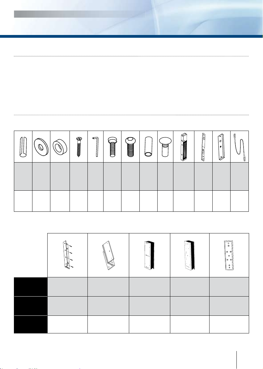
- Identi er le type de porte
(tirante ou poussante) et choisir
un accessoire en option si nécessaire.
- Percer un trou dans le montant
de la porte pour le passage
du câble jusqu’à la ventouse.
- Fixer solidement la plaque
de montage sur le dormant.
- Positionner sur l’ouvrant la contre-
plaque et l’ éventuel accessoire
et s’assurer qu’elle est montée
sans être bridée. La ventouse
peut être montée verticalement
ou horizontalement sur le dormant.
- Aligner la contre-plaque en vis
à vis de la ventouse.
- S’assurer que la ventouse est réglée
sur la tension correcte et appliquer
le courant. A la fermeture de la
porte, la contre-plaque doit
adhérer solidement à la ventouse.
4] RACCORDEMENT
Note importante :
Véri er la position du cavalier avant
de brancher la ventouse au courant
d’entrée de 24 V CC. Une position
incorrecte peut endommager la
ventouse. Ce type de dommage n’est
pas couvert par la garantie. 12 V DC 24 V DC
Tension
220/230 V AC
Alimentation
12/24 V DC
A l’intérieur
Bouton poussoir
Demande de sortie
Contrôle d’accès
extérieur
Exemples:
1. Lecteur proximité
2. Digicode®
3. lecteur Mifare®
Ventouse
Ventouse 300, 400
et 500 Kg, avec
relais + Buzzer
Réf. CDVI et DIGIT:
V3SRB - V4SRB - V5SRB
Ventouse 300, 400
et 500 Kg, avec relais.
Réf. CDVI:
V3SR - V4SR - V5SR
Réf. Digit:
P300ALR - P400ALR
- P500ALR
Ventouse 300, 400
et 500 Kg standard
Réf. CDVI:
V3S - V4S - V5S
Réf. Digit:
P300A - P400A - P500A
Le signal NO/NC ne commute que
lorsque la porte fermée et sous tension.
Cavaliers de sélection de tension
bornier Correspondance
+12 ou 24 V dc
--0 V
N.C
Normalement fermé
COM COM
N.O
Normalement ouvert
Signal