CE Electronics SK-75 User manual

Monitored Power Supply
INSTRUCTION MANUAL
CE Electronics Inc.
2107 Industrial Drive
Bryan, OH 43506
(419) 636-6705
www.ceelectronics.com

i
2
TABLE OF CONTENTS
Quick Start Guide............................................................................1
Introduction .....................................................................................3
Warnings .........................................................................................4
Unit Overview ................................................................................5
Monitor Mode .................................................................................7
Programming ..................................................................................8
AutoCalTM
Minimum Run Timer
Maximum Run Timer
Bump Timer
Start Current
Shut-Off Current
Maximum Current
Batch Count
Globilize
Relay & Beep
Count Direction
New Password
Digital Inputs
Current Draw
View Run Time
LCD Contrast
Unit Outline & Dimensions ..........................................................25
Power Supply Specifications.........................................................26
I/O Schematic ...............................................................................27
Parameter Selection ......................................................................28

1
Step 1:
Power up the unit. During
power-up the device will identify
the tool type for which the unit is
configured (either Brush or
Brushless). Be sure that the tool
to be used with this device
matches the tool type.
Step2:
Plug the tool into the tool con-
nector. Select the desired tool
speed (HI or LO). Turn the Soft
Start either ON or OFF.
Step 4:
Use the arrow keys to navigate
to the AutoCal option on the
program menu. Once at the
AutoCal option, press the enter
(ENT) button to select it.
Step 5:
The display will ask for a fasten-
er to be run. Run the tool on the
target fastener allowing the
clutch to turn the tool off. After
the clutch fires, the display
should read AUTOCAL COM-
PLETE Press Any Key.
Pressing a key will return the
unit to the program menu.
Quick Start Guide SK75-XX
2
Quick Start Guide (continued)
ENTER PASSWORD
****
Tool Type
BRUSH
Step3:
Press the enter (ENT) button
and enter the programming
mode. Either enter the pass-
word (0104 default) or bypass
the password by using the key.
PROGRAM MENU
AutoCal
ACAL BRUSH TOOL
Run Fastener
Step 6:
Use the arrow keys to navigate
to the Batch Count option on the
program menu. Once at the
Batch Count option press the
enter (ENT) button.
Step 8:
Pressing the escape (ESC) key
several times will return the unit
to the main run screens.
Use the arrow keys to select a
run screen that works best for
the application. The unit can
display status/count/batch,
total/count/batch, or status/total.
PROGRAM MENU
Batch Count A: STATUS CNT/BAT
BATCH OK 0/3
Step 7:
Use the up and down arrows to
modify the batch count by one.
The left and right arrows modify
this value by 10 in either direc-
tion (up or down).
When the desired batch count is
reached, pressing the enter
(ENT) button will store this
value.
BATCH COUNT P:A
Batch = 3

Warnings (continued):
Insert all fittings fully into their mating recepta-
cles. Failure to do so could result in injury.
Do not fold, bend or apply excessive force to
any cable or fitting.
Cautions:
Please use caution when handling this or any other electrical
appliance.
This unit accepts an AC input voltage from 100VAC to
240VAC. Trying to operate this unit with a voltage
outside that range may cause damage to the unit.
Avoid placing or storing this unit in a location where it
may become wet or dust covered.
Do not place or mount this unit in an unstable area.
Dropping this unit may result in personal injury or damage
to the unit.
Before performing any maintenance on the unit, make sure
to turn it off and remove the power plugs.
There are no user serviceable parts inside the main
enclosure of the unit.
4
Introduction:
Thank-you for your purchase of the SK75 monitored power sup-
ply! We are proud to be included as part of your assembly
process.
This document is an operations guide for the SK75. The SK75
can be outfitted to supply power for either brush or brushless
electric tools. The SK75 is also configured to monitor the tool
while it’s running. This feature can aid in the manufacturing
process by determining if a fastener has been installed properly
and also by counting the number of fasteners that have been
installed.
Before using the SK75, it is recommended that the user read this
manual thoroughly. If this unit is mishandled a fatal accident,
bodily injury, or damage to the SK75 may occur.
This manual is intended to be a general guide to the operations of
the SK75. If any additional questions or concerns arise, please
contact a CE Electronics representative.
Warnings:
Do not disassemble the unit for repair or modifi-
cations. There is a high electrical voltage inside
the unit that could cause electric shock.
Do not allow any type of liquid to come into
contact with any part of the unit.
Immediately discontinue use of the unit if
smoke, an abnormal odor, or an unusual sound
is detected coming from the unit.
3

Unit Overview (continued):
A five pin circular connector is located on the face
of the unit. This connector is used to supply
power to a tool and also to read signals back from
the tool.
Two selector switches are located above the tool
connector. The soft start switch turns the soft
start feature on and off. If the soft start feature
is enabled, the tool will spin slowly for a revo-
lution or two before jumping up to full speed.
Tool speed is governed by the speed switch.
When this switch is in the high setting, the
VDC out will be 30VDC. On the low setting, the power supply
provides 20VDC. The tool’s speed is directly proportional to out-
put voltage.
The rear panel on the unit
contains several items. The
main power switch for the
unit and the power entry
module are found on the
back panel. This unit is
capable of running on an
AC input voltage of 100VAC to 240VAC.
A keyswitch is provided on the unit’s back panel. The key switch
will allow a user to reach the programmable functions without
entering a password.
The unit’s beeper provides audible feedback when rejects occur
and can provide a double-beep when a batch accept occurs.
The RS-232 port can be used as a secondary means of program-
ming the unit or getting information from the unit.
6
Unit Overview
The user interface on the
SK75 is equipped with four
arrow buttons (up, down,
left and right) an enter but-
ton and an escape button.
These buttons are used dur-
ing programming.
The arrow keys are used to
navigate through menus,
raise and lower values dur-
ing programs, and move the
cursor to select items that
need to be edited.
The enter (ENT) button is typically used to select an item or save
a value once it has been edited. The escape (ESC) button is used
to abort an editing process without saving a new value
A two line by sixteen character
back-lit LCD display is part of the
user interface. This display will
provide the user with feedback dur-
ing the run mode and guide the user
through programming functions.
Above the LCD display, there are three status indicators. The
cycle status indicator will light up each time a fastening process is
completed successfully. The batch status indiction will be lit
when the final fastener is completed in a group. If a fastening
process is not completed properly, the reject status indicator will
illuminate.
The user interface on the SK75 can be mounted either in the face
of the unit or on the lid.
5
2x16 LED BACK-LIT
LCD DISPLAY
Tool Connector:
1. +VDC (out)
2. Limit (in)
3. DC GND
4. Drive (in)
5. Earth Ground
AC input and
power switch
Keyswitch Beeper
RS-232 I/O Connector

Monitor Mode (continued): The second monitor screen
shows current parameter, total
batches completed, current
count, and number of fasteners
in a batch.
The third monitor screen shows
current parameter, status of the
last fastening, and total number
of fasteners in the batch.
Programming Mode:
Pressing the enter (ENT) button while in the monitor mode will
send the unit into program mode.
If the keyswitch is in the
locked position, the user will
be prompted to enter a pass-
word before continuing.
To enter the password, use the
left and right arrow keys to
highlight a digit, only one number will be revealed at a time the
rest of the numbers will be obscured by asterisks. The up and
down arrows will allow the user to change the number that is
highlighted. Once all of the digits are entered properly, pressing
the enter button will allow the unit to proceed to the program
menu. Pressing escape will return the unit to the monitor mode.
8
Unit Overview (continued) :
The 12 pin connector on the back of the
unit contains several input and output
functions.
A remote start feature can be accessed by
shorting together pins 1 and 2. The
remote start feature needs to be enabled
by turning on dip-switch 2 on the
CE3068X board inside the unit.
All of the inputs are optically isolated. In
order to use an input, an external power
supply ground must be placed on pin 3 (Opto-Common). Then
that supply’s same regulated 24VDC can be used to reset the unit
on pin 4 or select one of eight parameters on pins 5,6 and 7.
Several relay outputs are provided to notify external systems
when events occur. In order to use a relay, a regulated voltage
needs to be placed on pin 12, relay common. When an even
occurs, that voltage will be returned on the relay pin that is asso-
ciated with the event. For example, when the tool is running, the
voltage that is placed on pin 12 will be returned on pin 11.
Monitor Mode:
There are three screens associated with the monitor mode.
Pressing any of the arrow keys allows the user to change the view
on the LCD screen.
The first of these screens will
show the current parameter,
status of the last fastening, cur-
rent count and the number of
fasteners in the batch.
7
PIN 1 PIN 12
I/O Connector:
1. Remote Start
2. Remote Start
3. Opto Common
4. Reset In
5. Param 2 In
6. Param 1 In
7. Param 0 In
8. Reject Relay Out
9. Batch Relay Out
10. Cycle Relay Out
11. Run Relay Out
12. Relay Common
A: STATUS CNT/BAT
CYCLE OK 2/3
Monitor Mode Screen #1
A: TOTAL CNT/BAT
30212 2/3
Monitor Mode Screen #2
A: STATUS TOTAL
BATCH OK 30212
Monitor Mode Screen #3
ENTER PASSWORD
****

Programming Mode (AutoCalTM):
The first item on the program
menu is AutoCalTM. AutoCalTM
is a calibration routine that is
meant to get the unit up and
running very quickly. In order
to use the AutoCalTM feature
press the enter button.
The display will read ACAL BRUSH TOOL
or ACAL B-LESS TOOL and Run Fastener.
Be sure that the right type of tool is being
used with the unit before proceeding.
At this point choose a typical fastener and
run it to completion allowing the clutch to
shut the tool off. Once the unit witnesses the
clutch stopping the process, all of the timers
and threshold will automatically be calculat-
ed and stored to non-volatile memory for the parameter set that
the unit was in at the beginning of the process.
While this data is stored, the display will read AUTOCAL COM-
PLETE, Writing..... Once the variables are stored, the display will
read AUTOCAL COMPLETE, Press Any Key. Pressing a key at
this point will return the unit to the programming menu.
The escape key can be pressed at any time during this process to
abort the calibration and return to the program menu without
changing the parameter data.
Programming Mode (Minimum Run Timer):
The minimum run timer defines
the minimum amount of time a
tool has to run during a fasten-
ing process in order to be con-
sidered a good fastening. If a
fastening process is shorter
than timer min, a Tmin reject
will be issued.
In order to edit this value enter the program
mode and press an arrow key until the dis-
play reads PROGRAM MENU, Timer Min.
Press the enter button in order to edit the
minimum run timer’s value.
After the enter button is pressed, the display
will read PROGRAM Tmin P:Y, Timer =
XX.XXX (where Y is the current parameter
and X is the current timer’s value).
Using the left and right arrow keys select the digit in the timer
value that needs edited. Once the appropriate digit is highlighted,
press the up and down arrows to change the digit’s value.
Proceed in this manner until all of the desired digits are edited.
Once the display shows the appropriate timer value, pressing the
enter button will store the new value to non-volatile memory and
the user will be prompted to Press Any Key. At this point any
button may be pressed and the unit will return to the program
menu.
During the editing process, if the escape button is pressed, the
unit will abort programming the minimum run time and return to
the main programming menu.
10
9
PROGRAM MENU
AutoCal
PROGRAM MENU
AutoCal
ACAL BRUSH TOOL
Run Fastener
AUTOCAL COMPLETE
Writing....
Run target
fastener
AUTOCAL COMPLETE
Press Any Key
PROGRAM MENU
Timer Min
PROGRAM MENU
Timer Min
PROGRAM Tmin P:A
Timer = 00.234
TIMER MIN SAVED
Writing....
Edit Timer
Value
TIMER MIN SAVED
Press Any Key

Programming Mode (Bump Timer):
The bump timer defines an
amount of time that a tool can
run and that run will be ignored
if the clutch does not fire (i.e.
torque is not achieved). This
timer may be used to eliminate
nuisance rejects.
In order to edit this value enter the program
mode and press an arrow key until the dis-
play reads PROGRAM MENU, Timer
Bump.
Press the enter button in order to edit the
bump timer’s value.
After the enter button is pressed, the display
will read PROGRAM Tbmp P:Y, Timer =
XX.XXX (where Y is the current parameter
and X is the current timer’s value).
Using the left and right arrow keys select the digit in the timer
value that needs edited. Once the appropriate digit is highlighted,
press the up and down arrows to change the digit’s value.
Proceed in this manner until all of the desired digits are edited.
Once the display shows the appropriate timer value, pressing the
enter button will store the new value to non-volatile memory and
the user will be prompted to Press Any Key. At this point any
button may be pressed and the unit will return to the program
menu.
During the editing process, if the escape button is pressed, the
unit will abort programming the bump timer and return to the
main programming menu.
12
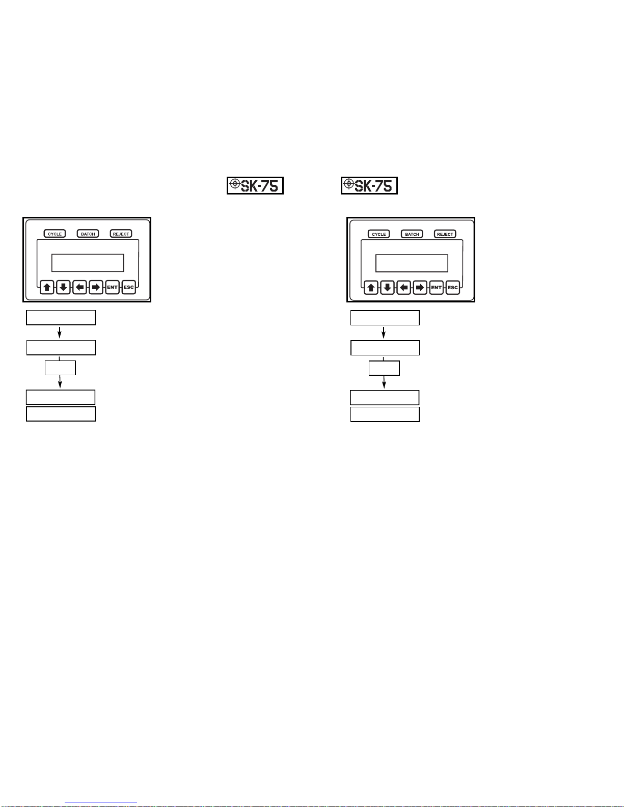
Programming Mode (Maximum Run Timer):
The maximum run timer
defines the maximum amount
of time a tool can run during a
fastening process and still be
considered a good fastening. If
a fastening takes longer than
timer max, a Tmax reject will
be issued.
In order to edit this value enter the program
mode and press an arrow key until the dis-
play reads PROGRAM MENU, Timer Max.
Press the enter button in order to edit the
maximum run timer’s value.
After the enter button is pressed, the display
will read PROGRAM Tmax P:Y, Timer =
XX.XXX (where Y is the current parameter
and X is the current timer’s value).
Using the left and right arrow keys select the digit in the timer
value that needs edited. Once the appropriate digit is highlighted,
press the up and down arrows to change the digit’s value.
Proceed in this manner until all of the desired digits are edited.
Once the display shows the appropriate timer value, pressing the
enter button will store the new value to non-volatile memory and
the user will be prompted to Press Any Key. At this point any
button may be pressed and the unit will return to the program
menu.
During the editing process, if the escape button is pressed, the
unit will abort programming the maximum run time and return to
the main programming menu.
11
PROGRAM MENU
Timer Max
PROGRAM MENU
Timer Max
PROGRAM Tmax P:A
Timer = 03.456
TIMER MAX SAVED
Writing....
Edit Timer
Value
TIMER MAX SAVED
Press Any Key
PROGRAM MENU
Timer Bump
PROGRAM MENU
Timer Bump
PROGRAM Tbmp P:A
Timer = 00.000
TIMER BUMP SAVED
Writing....
Edit Timer
Value
TIMER BUMP SAVED
Press Any Key

Programming Mode (Shut-Off Current):
The shut-off current defines the
minimum amount of current
that needs to be drawn by a
brushless tool when the tool
clutches out. This threshold
can be used as a secondary
check for the tool’s clutch set-
ting. The shut-off current
value is only used with brushless tools.
In order to edit this value enter the program
mode and press an arrow key until the dis-
play reads PROGRAM MENU, Shut-Off
Current.
Press the enter button in order to edit the
shut-off current’s value.
After the enter button is pressed, the display
will read SHUTOFF CRNT P:Y, TRIP = X.XX A (where Y is the
current parameter and X is the amperage value in amps).
Use the left or down arrow key to lower this value. The right or
up arrow key will raise the value. Proceed in this manner until
the appropriate current is displayed.
Once the display shows the appropriate amperage value, pressing
the enter button will store the new value to non-volatile memory
and the user will be prompted to Press Any Key. At this point any
button may be pressed and the unit will return to the program
menu.
During the editing process, if the escape button is pressed, the
unit will abort programming the shut-off current and return to the
main programming menu.
14
Programming Mode (Start Current):
The start current defines the
amount of current that needs to
be drawn by a brushless tool
before the unit is considered to
be in cycle. Once the tool
starts drawing this amount of
current, the run-timers will
start. The start current value
is only used with brushless tools.
In order to edit this value enter the program
mode and press an arrow key until the dis-
play reads PROGRAM MENU, Start
Current.
Press the enter button in order to edit the
start current’s value.
After the enter button is pressed, the display
will read STRT CURRENT P:Y, TRIP = X.XX A (where Y is the
current parameter and X is the amperage value in amps).
Use the left or down arrow key to lower this value. The right or
up arrow key will raise the value. Proceed in this manner until
the appropriate current is displayed.
Once the display shows the appropriate amperage value, pressing
the enter button will store the new value to non-volatile memory
and the user will be prompted to Press Any Key. At this point any
button may be pressed and the unit will return to the program
menu.
During the editing process, if the escape button is pressed, the
unit will abort programming the start current and return to the
main programming menu.
13
PROGRAM MENU
Start Current
PROGRAM MENU
Start Current
STRT CURRENT P:A
TRIP = 0.20 A
THRESHOLD SAVED
Writing....
Edit Current
Value
THRESHOLD SAVED
Press Any Key
PROGRAM MENU
Shut-Off Current
PROGRAM MENU
Shut-Off Current
SHUTOFF CRNT P:A
TRIP = 0.00 A
THRESHOLD SAVED
Writing....
Edit Current
Value
THRESHOLD SAVED
Press Any Key

Programming Mode (Batch Count):
The Batch Count is typically
programmed to be the number
of fasteners in a given assem-
bly. A Cycle Accept signal will
be generated each time a prop-
er fastening occurs. A Batch
Accept however, will occur
when the count reaches the
batch value.
In order to edit this value enter the program
mode and press an arrow key until the dis-
play reads PROGRAM MENU, Batch Count.
Press the enter button in order to edit the
batch count’s value.
After the enter button is pressed, the display
will read BATCH COUNT P:Y, Batch = X
(where Y is the current parameter and X is the number of fasten-
ers in a batch).
Use the up or down arrow key to raise or lower the batch value by
1. The left and right arrow keys will raise or lower the value by
10. Proceed in this manner until the appropriate batch value is
displayed.
Once the display shows the appropriate batch, pressing the enter
button will store the new value to non-volatile memory and the
user will be prompted to Press Any Key. At this point any button
may be pressed and the unit will return to the program menu.
During the editing process, if the escape button is pressed, the
unit will abort programming the batch value and return to the
main programming menu.
16
Programming Mode (Max Current):
The maximum current defines
the maximum amount of cur-
rent that can be drawn by a
brushless tool when the tool
clutches out. This threshold
can be used as a secondary
check for the tool’s clutch set-
ting. The max current value
is only used with brushless tools.
In order to edit this value enter the program
mode and press an arrow key until the dis-
play reads PROGRAM MENU, Max
Current.
Press the enter button in order to edit the
max current’s value.
After the enter button is pressed, the display
will read MAX CURRENT P:Y, TRIP = XX.XX A (where Y is
the current parameter and X is the amperage value in amps).
Use the left or down arrow key to lower this value. The right or
up arrow key will raise the value. Proceed in this manner until
the appropriate current is displayed.
Once the display shows the appropriate amperage value, pressing
the enter button will store the new value to non-volatile memory
and the user will be prompted to Press Any Key. At this point any
button may be pressed and the unit will return to the program
menu.
During the editing process, if the escape button is pressed, the
unit will abort programming the max current and return to the
main programming menu.
15
PROGRAM MENU
Max Current
PROGRAM MENU
Max Current
MAX CURRENT P:A
TRIP = 10.00 A
THRESHOLD SAVED
Writing....
Edit Current
Value
THRESHOLD SAVED
Press Any Key
PROGRAM MENU
Batch Count
PROGRAM MENU
Batch Count
BATCH COUNT P:A
Batch = 3
BATCH SAVED
Writing....
Edit Current
Value
BATCH SAVED
Press Any Key

Programming Mode (Relay & Beep):
The output relays in this sys-
tem can be programmed to be
either momentary or latching.
If the relays are momentary the
will close briefly (200ms)
when and event occurs. When
set to latching, the relay closes
and remains that way until the
tool starts running again.
The beeper in this system can be pro-
grammed to double-beep when a batch
accept occurs.
In order to edit these items enter the program
mode and press an arrow key until the dis-
play reads PROGRAM MENU, Relay &
Beep. Press the enter button in order to edit
relay or beeper settings.
After the enter button is pressed, the display will read PGM
RELAY/BEEPER, RLY XXX BEEP YYY (where X is either
MOM for momentary or LAT for latching and Y is either ON or
OFF).
Using the arrow keys set the desired relay and beeper setting.
Once the display shows the appropriate settings, pressing enter
will save the settings to non-volatile memory and the user will be
prompted to Press Any Key. At this point any button may be
pressed and the unit will return to the program menu.
During the editing process, if the escape button is pressed, the
unit will abort this particular programming process and return to
the main programming menu.
18
Programming Mode (Globalize):
Often, when multiple parameter
sets are used, only one or two
variables within the parameter
sets needs to vary. It’s very
common to have everything
within multiple parameter sets
be identical except for a varia-
tion in the batch count. If this
is the case, globalizing a parameter set may
help to speed the programming process.
When globilization is used one parameter set
is copied to all of the other parameters.
In order to select a parameter for globaliza-
tion enter the program mode and press an
arrow key until the display reads PROGRAM
MENU, Globalize.
Press the enter button in order to the global-
ization option.
After the enter button is pressed, the display will read GLOBAL-
IZE PARAM, Parameter = Y (where Y is the parameter that will
be copied to all other parameters if selected).
Using the arrow keys select the parameter set to be copied.
Once the display shows the appropriate parameter, pressing the
enter key will copy that parameter to all of the other parameters
and the user will be prompted to Press Any Key. At this point any
button may be pressed and the unit will return to the program
menu.
During the editing process, if the escape button is pressed, the
unit will abort the globalization and return to the main program-
ming menu.
17
PROGRAM MENU
Globalize
PROGRAM MENU
Globalize
GLOBALIZE PARAM
Parameter = A
GLOBALIZE PARAM
Writing....
Edit Current
Value
GLOBALIZE SAVED
Press Any Key
PROGRAM MENU
Relay & Beep
PROGRAM MENU
Relay & Beep
PGM RELAY/BEEPER
RLY MOM BEEP OFF
RLY/BEEPER SAVED
Writing....
Edit Current
Value
RLY/BEEPER SAVED
Press Any Key

Programming Mode (New Password):
In order to enter the program-
ming mode, either the key-
switch was used or a password
was entered. The default pass-
word of 0104 can be overwrit-
ten and set to any four digit
number.
In order to change the password, enter the
program mode and press an arrow key until
the display reads PROGRAM MENU, New
Password. Press the enter button in order to
edit the password.
After the enter button is pressed, the display
will read PROGRAM PASSWORD/0***.
The left and right arrow keys can be used to
select any of the four digits in the password.
Once the desired digit is high-lighted, the up and down arrow
keys will allow the user to change that digit. Only the digit being
edited will be visible. The other digits will be obscured and an
asterisks will appear as a place holder.
Once the desired password has been entered, pressing enter will
save the settings to non-volatile memory and the user will be
prompted to Press Any Key. At this point any button may be
pressed and the unit will return to the program menu.
During the editing process, if the escape button is pressed, the
unit will abort this particular programming process and return to
the main programming menu.
20
Programming Mode (Count Direction):
This unit can be programmed
to count up from zero until the
batch is reached or count down
from the batch to zero.
In order to edit this function,
enter the program mode and
press an arrow key until the
display reads PROGRAM MENU, Count
Direction. Press the enter button in order to
edit the Count Direction.
After the enter button is pressed, the display
will read COUNT DIRECTION/Count XXX
(where X is either UP or DOWN).
Using the arrow keys set the desired count
direction (either up or down) .
Once the display shows the appropriate setting, pressing enter
will save the settings to non-volatile memory and the user will be
prompted to Press Any Key. At this point any button may be
pressed and the unit will return to the program menu.
During the editing process, if the escape button is pressed, the
unit will abort this particular programming process and return to
the main programming menu.
19
PROGRAM MENU
Count Direction
PROGRAM MENU
Count Direction
COUNT DIRECTION
Count UP
COUNT DIRECTION
Writing....
Edit Current
Value
DIRECTION SAVED
Press Any Key
PROGRAM MENU
New Password
PROGRAM MENU
New Password
PROGRAM PASSWORD
0 * * *
PROGRAM PASSWORD
Writing....
Edit Current
Value
PROGRAM PASSWORD
Press Any Key

Programming Mode (Current Draw):
The Current Draw menu option
is a trouble shooting mode.
This mode can be particularly
handy when deciding how to
program the Start Current,
Shut-Off Current, and Max
Current for a brushless tool.
If this item is selected, the SK-75 will act
like a current meter showing the user how
much current is being drawn by the tool
(either brush or brushless).
In order to view this value, enter the program mode and press an
arrow key until the display reads PROGRAM MENU, Current
Draw. Press the enter button in order to monitor the tool’s current
use.
Once in this mode, the bottom line of the LCD will display the
current draw in amps. This value will be constantly updated
while in this mode.
The unit will exit this mode if any key is pressed.
22
Programming Mode (Digital Inputs):
The Digital Inputs menu option
is a trouble shooting mode. If
this item is selected, the signals
that the tool is sending the SK-
75 can be monitored.
In order to view these signals,
enter the program mode and
press an arrow key until the display reads
PROGRAM MENU, Digital Inputs. Press
the enter button in order to monitor the tool’s
digital signals.
Once in this mode, the left side of the display will show the state
of the tool’s run request signal. That side of the display will
either read RUN ON or RUN OFF. In a brush tool, this signal
should be off until the run switch is activated (either though a
lever or push to start).
In a brushless tool, the left side of the display will always read
RUN ON because most brushless tools constantly issue a run
request even if the tool’s run switch is off.
The right side of the display shows the state of the tool’s clutch or
limit switch. This message will read BRK OFF most of the time.
When a tool clutches out (either brush or brushless) this message
will briefly read BRK ON.
The unit will exit this mode if any key is pressed.
21
PROGRAM MENU
Digital Inputs
PROGRAM MENU
Digital Inputs
DIGITAL INPUTS
RUN OFF / BRK OFF
PROGRAM MENU
Current Draw
PROGRAM MENU
Current Draw
CURRENT DRAW
0.00 A

Programming Mode (LCD Contrast):
The LCD display can be
adjusted so that the text is
darker or lighter by accessing
the LCD Contrast feature.
In this mode, the display will
show a value that represents a
contrast setting for the display.
As that value is altered the user can see what
effect it has on the view-ability of the dis-
play.
In order to view this value, enter the pro-
gram mode and press an arrow key until the
display reads PROGRAM MENU, LCD
Contrast. Press the enter button in order to
adjust the display’s contrast.
Once in this mode, the bottom line of the
LCD will display the Contrast = X (where X is a number that rep-
resents the current setting). Using an arrow key, the contrast
value can be adjusted.
Once the display’s contrast suits the user, that new contrast can be
saved to non-volatile memory by pressing the enter key.
The unit will exit this mode without saving a new contrast setting
if the escape key is pressed.
24
Programming Mode (View Run Time):
Another trouble shooting
mode/programming aid is the
“View Run Time” mode.
In this mode, the display will
show how long the tool ran
during the previous fastening
cycle.
In order to view this value, enter the pro-
gram mode and press an arrow key until the
display reads PROGRAM MENU, View Run
Time. Press the enter button in order to
monitor the tool’s current use.
Once in this mode, the bottom line of the LCD will display the
amount of time that elapsed during the last fastening cycle. This
value will be updated automatically each time the tool runs.
This information can be very useful in determining what values
should be used for the minimum and maximum run times.
The unit will exit this mode if any key is pressed.
23
PROGRAM MENU
View Run Time
PROGRAM MENU
View Run Time
VIEW RUN TIME
Time = 0.345s
PROGRAM MENU
LCD Contrast
PROGRAM MENU
LCD Contrast
LCD CONTRAST
Contrast = 12
CONTRAST SAVED
Writing....
Edit Current
Value
CONTRAST SAVED
Press Any Key

Power Supply Specifications:
Input Specifications:
Input Voltage Range 85-264 VAC
Input Current 2.2A/115VAC 1.1A/230VAC
Frequency 47-440Hz
Power Factor >=0.96/230V, >=0.98/115V
Output Specifications:
Output Voltage (Low) 20VDC
Output Voltage (High) 30VDC
Output Power 150 Watts
Minimum Load 0A
Output Tolerance +/- 2%
Ripple Noise 150mVp-p, typical
Overload Protection 105~150%, Constant Current Limit
Auto Recovery
Setup/Rise/Holdup(230VAC) 600ms/30ms/20ms
General Specifications:
Input/Output Isolation I/P-O/P 3000VAC
I/P-G 1500VAC
O/P 0.5KVAC
Efficiency 80% typical
Switching Frequency 135Khz (fixed, typical)
MTBF 191,800 Hrs (21.9 years)
26
Unit Outline and Dimensions:
25

Parameter Section:
28
I/O Schematic:
Input Specifications:
All Inputs Optically Isolated
Remote Start Short Pin 1 to Pin 2 to use
Reset Ground Pin 3 & Apply 24VDC to
Pin 4 (Momentary)
Parameter Inputs Ground Pin 3 & Apply 24VDC to
Pins 5 and/or 6 and/or 7
(Maintained)
Binary Parameter Selection
Output Specifications:
Relay Specification 2A Max Current
220VDC Max Switching Voltage
60W Max Switching Power
27
1
2
3
4
5
6
7
8
9
10
11
12
Remote Start
Remote Start
Opto-Input Common
Reset Input
Parameter 2 Input
Parameter 1 Input
Parameter 0 Input
Reject Relay Out
Batch Relay Out
Cycle Relay Out
Run Relay Out
Relay Common
1.5K
1.5K
1.5K
1.5K
1.5K
2A Relay
2A Relay
2A Relay
SK-75 I/O Schematic
INPUTS
OUTPUTS
2A Relay
+VDC
Parameter Parameter 2
Input Parameter 1
Input Parameter 0
Input
A0VDC 0VDC 0VDC
B0VDC 0VDC 24VDC
C0VDC 24VDC 0VDC
D0VDC 24VDC 24VDC
E24VDC 0VDC 0VDC
F24VDC 0VDC 24VDC
G24VDC 24VDC 0VDC
H24VDC 24VDC 24VDC

PN-11500032
D082404
Copyright © 2004 C.E. Electronics, Inc. All Rights Reserved
C.E. Electronics, Inc.
2107 Industrial Drive
Bryan, OH 43506
PH (419) 636-6705
FX (419) 636-2516
Table of contents
Popular Power Supply manuals by other brands

Sherlotronics
Sherlotronics 3.2AMP installation instructions

R&S
R&S NGE100B Series user manual

Horizont
Horizont FARMER AN15 operating instructions

Functional Devices
Functional Devices PSC100AB10 installation instructions

Alpha Technologies
Alpha Technologies APP60S Operator's manual

OCZ
OCZ Z SERIES 850W manual