Ceasa SET&SOFT User manual

SHOWER SOFTENER-CEASA 1

2 SHOWER SOFTENER-CEASA
Application: The product is mainly used for shower water softening, but can also be used for
floor heating, beauty salons, hairdressing salons, washing machines etc.
The softener water is not drinkable.
Please note:
1. Due to occasional updates, some of the text or designs in the manual
may differ from the actual product. Please refer to the actual product.
2. All data has been carefully checked. If there are any printing or
content errors, we reserve the right of interpretation.

SHOWER SOFTENER-CEASA 3
Table of contents
1. Product list…………………………………………………………………………………………………………………………………5
2. Product overview……………………………………………………………………………………………………………………….6
2.1 Characteristics
2.2 Technical Parameters
2.3 Technological Processing of Water
2.4 Appearance and Dimensions
2.5 Structure
3. Installation………………………………………………………………………………………………………………………………….8
3.1 Installation Instructions
3.2 Product Installation
3.2.1 Preparation of Tools
3.2.2 Installation Position
3.3 Pipeline Installation Instructions
3.3.1 Installation after Water Heater
3.3.2 Installation before Water Heater
3.3.3 Drain Pipeline Installation
3.3.4 Power Wire Installation
4. Trial Run……………………………………………………………………………………………………………………………………22
5. Regeneration Operation……………………………………………………………………………………………………………22
5.1 Water Capacity
5.2 Regeneration Salt Consumption
5.3 Regeneration Process
6. Resin Replacement……………………………………………………………………………………………………………………25
7. Parameter Setting…………………………………………………………………………………………………………………….28
7.1 Product Control Panel Overview
7.2 Main Board Socket Overview
7.3 Product Installation Mode Setting
7.4 Regeneration Reminder Day Setting
7.5 Meaning of Operation Codes
8. Troubleshooting……………………………………………………………………………………………………………………….31
9. Warranty Card………………………………………………………………………………………………………………………….32
INDEX

4 SHOWER SOFTENER-CEASA
1. If accessories are required, please purchase superior quality products.
2. Given the particular nature of the environment where the product is used, all the components of
the shower softener have a certain service life. The service life of the main components is listed
in the user manual. Please replace components in accordance with the requirements.
3. The user manual provides guidelines for the correct use of this product. Please strictly follow
the user manual instructions regarding operation, routine inspection and maintenance.
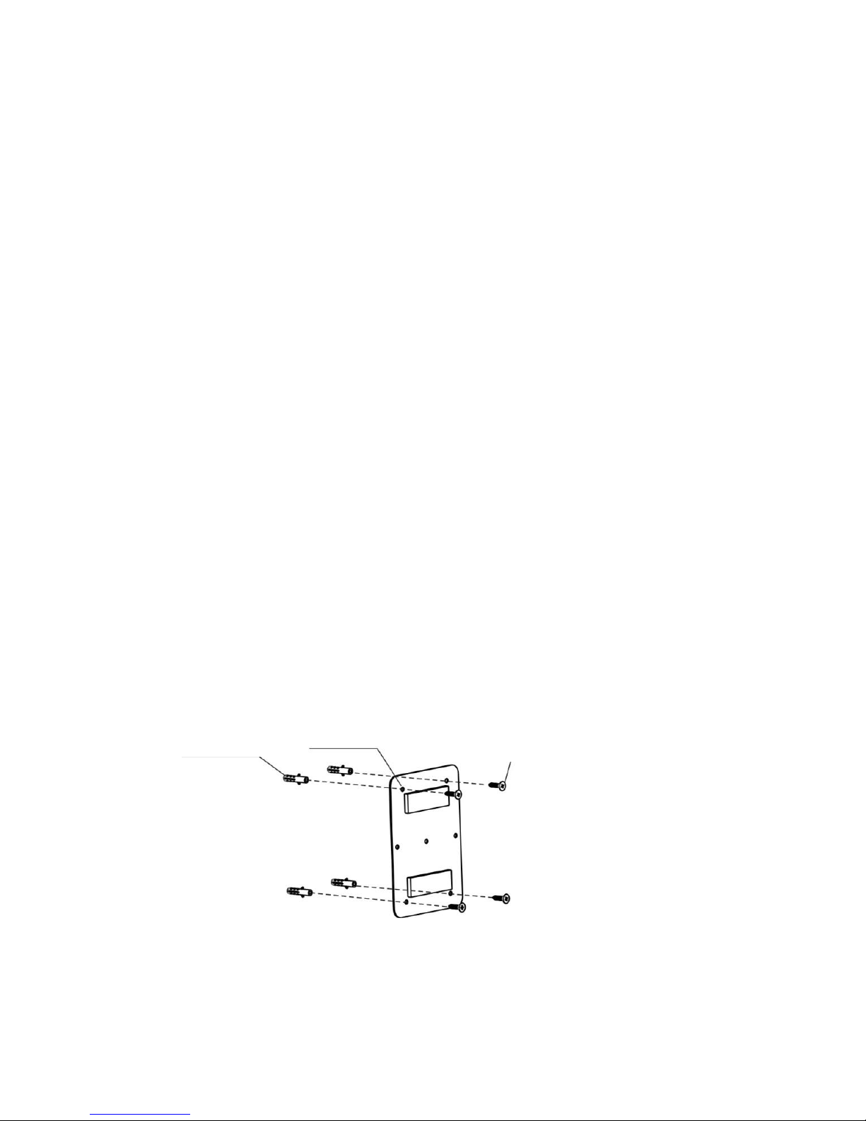
4. We recommend that this product is installed by a qualified professional appointed by the
company authorized distributor. Users must provide details about the mounting surface (such as
the installation surface material, water and electrical layout) for installation.
5. This product is suitable for municipal tap water, with a water pressure of 0.1~0.6 Mpa and a
water temperature of 5℃-70℃. Not permitted for use outside this range.
6. The product is only suitable for indoor installation and use. It must be installed in a cool and dry
place, away from direct sunlight. Avoid exposing the pipe connected to the product to light, heat,
corrosive environments and impact from sharp objects.
7. This product should be installed at around 1 meter from a reliable worldwide floor drain for
drainage.
8. Never spray water on this product.
9. In case of product failure, please cut off the water supply and contact your distributor as soon as
possible.
10. In order to ensure efficient regeneration, please use our company-approved regeneration salt
particles where possible.
11. If the transformer and wire are damaged, they must be replaced at our factory.
12. Since the product needs electricity to operate, please do not install the transformer in a location
where water splashes are possible.
13. Our company shall not be liable for any damage resulting from operation not in accordance with
the above considerations.
NOTICE

SHOWER SOFTENER-CEASA 5
Name
Quantity
Remarks
Shower softener
1
Stainless steel plate
1
Transformer
1
3 meters
Accessories
1
Expansion
tube/screw/gasket
User manual
1
Certification
1
Optional accessories
Name
Quantity
Remarks
Braided hose
1
600mm
Cut-off filter
1
¼" Drain pipe
3
Cold water connector
1
Installation before the
water heater
Hot water connector
1
Installation before the
water heater
½" Elbow
1
Installation before the
water heater
1. PRODUCT LIST
Note: Optional accessories are required to install the product before the water heater.
If needed, please purchase from your distributor.

6 SHOWER SOFTENER-CEASA
2.1. Characteristics
●Wall-mounted, no brine tank, small volume.
●Dynamic regeneration mode. Higher water capacity. Save salt and water.
●Extensive applicability: installation before or after the water heater. Installed before
the water heater, it prevents scaling in the heater.
●Automatically controlled regeneration time, one button to perform regeneration. No
need for human supervision. LED display.
●Days of use reminder, next regeneration time display.
●Automatic backwash function that reduces resin hardening and strainer blockage to
improve resin service life.
●Built-in quick connector for easier maintenance and resin replacement.
●Outlet with check valve to prevent the backflow of water from the water heater.
●Data saved after power off.
2.2. Technical Parameters
Item
Requirements
Work Pressure
0.1~0.6MPa
Water Temperature
5℃~70℃
Environment Temperature
5℃~50℃
Transformer
AC100~240V/50~60Hz
Water regeneration capacity
750L
Water inlet/outlet specification
G1/2
Regeneration salt consumption
400g
Suitable water
Tap water
2. PRODUCT OVERVIEW

SHOWER SOFTENER-CEASA 7
Water quality: Conform to the “Health safety evaluation specifications and functions
for drinking-quality water processors -- general water processors” (2001)
All operating parameters for this product have been measured under standard test
conditions (total water hardness test in CaCO3, 200 mg/-), and will change under
different operating conditions
2.3. Technological Processing of Water
Tap Water Na cationic resin Soft water
2.4. Appearance and Dimensions
Product Diagram
Drain pipe
Outlet
Inlet

8 SHOWER SOFTENER-CEASA
2.5. Structure
3.1. Installation Instructions
This product can be installed in one of two ways:
A. Installation before the water heater
Advantage: Softens water first, then heats it, to prevent scaling in the water heater,
save energy and protect the environment, and soften the bathing water.
B. Installation after the water heater
Advantage: The installation after the water heater is convenient for pipeline
installation, softens the bathing water, and is suitable for users looking to decorate.
Salt tank cover
Soluble salt tank
Resin
Riser pipe
Resin tank
Control valve
3. INSTALLATION

SHOWER SOFTENER-CEASA 9
The installation method must be chosen between the above two according to the
user’s needs.
3.2. Product Installation
This product features a wall-mounting system. Please rely on a professional for the
installation. If you decide to install it yourself, please follow the steps below.
3.2.1. Preparation of Tools
The following tools are required for installation: adjustable wrench, pipe wrench,
screwdriver and percussion drill.
3.2.2. Installation Position
(For details on the product installation method to determine the installation position
and pipe connection, please refer to the pipe installation instructions in the user
manual).
When this product fails to use the resin, salt needs to be added for the regeneration. In
order to add salt, the user can choose at what height to hang the product based on
their own height. This product should be installed at around 1 meter from a reliable
worldwide floor drain.
Product wall-mounting steps:
2.1 Open the package and check if the softener is complete and all accessories
are included.

10 SHOWER SOFTENER-CEASA
2.2 Remove the expansion screws and stainless steel plate. Use the holes in the
plate as a reference to mark the drilling locations on the wall using the
percussion drill. Our company provides expansion screws for ST3.9 x30, so
we recommend selecting a 6 mm diameter drill bit. When selecting the height
to hang the product, please give priority to what is convenient for you in terms
of adding salt.
2.3 Normally the stainless steel plate can be installed using just four expansion
screws in a diagonal pattern in soft walls, such as wood, lime…Installation
under other special conditions may require more screws. Please refer to figure
1.
2.4 Insert the expansion screw tube into the drilled hole, then use a screwdriver
to fix the plate to the wall, as shown in figure 2, with the raised side facing
outwards.
2.5 Install the unit on the slots of the fixed plate, then complete the hanging
process. The appearance after installation is shown in figure 3.
Figure 1. Install the stainless steel plate
Expansion screw tube
Stainless steel plate
Self-tapping
screw

SHOWER SOFTENER-CEASA 11
Figure 2. The unit is fixed to the wall Figure 3. Appearance after installation
3.3. Pipeline Installation Instructions
3.3.1 Installation after Water Heater
Reminder: If there is no spare faucet in the bathroom, there will be no water flow
during regeneration. Please reserved a spare outlet for this purpose during
installation.
Installation steps:
1.1 Close the water mixing valve; use an adjustable wrench to unscrew the hand-held
shower nozzle and the nut from the water mixing valve connection as shown in
figure 4. Tighten the nut of the shower head to the outlet of the unit, as shown
in figure 5.
Fixed unit
Plate
mounted on the wall
Suggested height:
less
than 1.7 meters

12 SHOWER SOFTENER-CEASA
Figure 4. Unscrewing the shower nozzle and nut from the water mixing valve
Figure 5. The nozzle is tightened to the unit
1.2 Connect the outlet of the water mixing valve to the unit inlet connection with a
braided hose or bellows. To select the installation location for the unit,
determine the water pipe connection. This manual describes several common
installation methods as a reference for the user.
a. If the surrounding space already has a spare faucet installed, the unit can be
installed to the left or the right of the water mixing valve depending on the
space available, as shown in figure 6 and figure 7.
Unscrew the nut
with a wrench
The nut of the nozzle is
tightened to the unit

SHOWER SOFTENER-CEASA 13
Figure 7. Installation diagram of the unit on the right side of the water mixing valve
Bellows joint recommended
Figure 6. Installation diagram of the unit on the left side of the water mixing valve
Use bellows joint or tube
Suggested distance:
less than 300mm

14 SHOWER SOFTENER-CEASA
b. If the surrounding space has no spare outlet and water is needed for
regeneration, we recommend installing the unit on the reserved outlet in the
water mixing valve outlet pipe, to the left or the right of the water mixing valve
depending on the space requirements, as shown in figure 8 and figure 9.
Figure 8. Installation diagram of the unit on the right side of the water mixing valve using the reserved outlet
Reserved outlet

SHOWER SOFTENER-CEASA 15
Figure 9. Installation diagram of the unit on the left side of the water mixing valve using the reserved outlet
3.3.2. Installation before Water Heater
Note: Installation before the water heater is relatively complicated and requires
some accessories that must be purchased from a dealer.
Required accessories
No.
Name
Diagram
Remarks
1
Hot water connector
On the connector
engraved with “H”
2
Cold water connector
On the connector
engraved with “C”
3
Cut-off
filter valve
Selection
4
½" Elbow
Reserved outlet

16 SHOWER SOFTENER-CEASA
Below are the installation steps for installation before the water heater
Install the cold and hot water connectors
a. Shut off the water supply, remove the water mixing valve with a wrench,
keeping the center distance of the eccentric connection invariable, as shown in
figure 10.
b. Take out the cold and hot water connectors and ¾" flat gasket from the
accessories box. Refer to the chart to remove the cold and hot water connectors
installed on the wall from the eccentric connections, taking care not to damage
the flat gasket, as shown in figure 11.
c. Use the wrench to connect the cold water connector of the water mixing valve
to the cold water connection, and the hot water connector to the hot water
connection, taking care to maintain the integrity of the flat gasket, as shown in
figure 12.
d. Following the diagram of the installed water mixing valve and the signs on the
connection, place the cold water outlet facing down, as shown in figure 13.
e. In order to prevent large particles from entering into the softener from the
pipeline, which could affect the operation, we suggest that users install a cut-off
filter valve. Take out the cut-off filter valve and flat gasket, tighten the cold
water connection to the tap water connection, placing the flat gasket as shown
in figure 14. Appearance after installation is shown in figure 15.

SHOWER SOFTENER-CEASA 17
Figure 10. Disassembled water mixing valve Figure 11. Water mixing valve installed on the connector
Figure 12. Installation of cold and hot water connectors
Figure 13. Appearance after installation Figure 14. Installation diagram of cut-off filter valve
Eccentric connector
Water mixing
valve
Flat gasket
Water mixing
valve
¾" Flat gasket
Hot water port connector
Cold water port connector
½" flat
gasket
Cut-off filter valve

18 SHOWER SOFTENER-CEASA
Figure 15. Appearance after installation of cut-off filter valve
3.3.3 Drain Pipeline Installation
a. Connect the ½" articulated elbow to the outlet behind the unit. Remove the
end cap from the outlet behind the unit as shown in figure 16. Take out the ½"
articulated elbow from the accessories box and tighten it to the outlet as shown
in figure 17, with the flat gasket. Appearance after installation is shown in
figure 18.
b. Choose the appropriate position to hang the unit on the wall (with reference to
the previous product installation instructions).
Figure 16 Figure 17 Figure 18
Back outlet
End cap
½" Flat
gasket
½" Articulated
elbow
½" Flat
gasket

SHOWER SOFTENER-CEASA 19
c. Use a braided hose or corrugated pipe to connect the water inlet to the unit,
connect one outlet to the inlet of the water heater and another outlet to the cold
water port of the water mixing valve.
Please keep in mind that the product will have no water flow during
regeneration. If the users need water during regeneration, then we suggest
reserving a spare outlet when installing the domestic water supply pipe. For
customer reference, figure 19 and figure 20 show a common installation
diagram. Figure 21 shows a closeup of the cold water connection.
Figure 19. Diagram of installation before the water heater
Embedded pipe installed
Water heater
Outlet connected to cold water
connection
Outlet connected to water heater
Cut-off filter valve
Water heater

20 SHOWER SOFTENER-CEASA
Figure 20. Diagram of installation before the water heater reserved outlet
Figure 21. Cold water connection diagram
3.3.3. Drain Pipeline Installation
This product is factory-equipped with a drain pipe. If the drain pipe needs to be
extended because the water pipe is farther or for other reasons, please use the
1/4" quick connector. Pay attention to the flow control connector. The drain hose
is correctly installed when connected as shown in figure 22. Please contact your
distributor if you lose it.
Back pipe
Reserved outlet
Cut-off filter valve
Connection to cold
water
Connection to water heater
Cold water connection to mixing water
valve
Water outlet to unit
Water inlet to unit
Main water inlet
Table of contents
Other Ceasa Water Dispenser manuals
Popular Water Dispenser manuals by other brands

Bunn
Bunn H5E OPERATING & SERVICE MANUAL

EcoWater
EcoWater Atlas 9 owner's manual

Platinum
Platinum 6960436 instruction manual

Halsey Taylor
Halsey Taylor HydroBoost HTHBHVR8 owner's manual

DS Services of America
DS Services of America pure water dispenser 200k Series How to Clean

Elkay
Elkay VRC8TLWS Series Installation and use manual

aQuatell
aQuatell Fleck 5600SXT instructions

Pentair
Pentair SOLEO SB-PF-SOL-003C Installation and user guide

Follett
Follett Symphony Plus 12 Series installation guide

WaterGroup
WaterGroup Econoflo ECS20 Installation and maintenance instruction manual

BestWater
BestWater Jungbrunnen 25-00 instruction manual

ClearStream
ClearStream 500DAST manual