Operation guide
page 6
5. Operation guide
This dispenser is intended for water dispensing only. Do NOT use other liquids. Do NOT use
for other purposes. Warranty is void if used for any other liquids including coffee, tea, juices,
beer or wine.
This dispenser has been designed to use water bottles with a 3, 5 or 5.2 gallon capacity. Do
NOT use alternative bottles.
Initial Set Up
Do NOT plug in until steps 1-3 are completed.
1. Allow unit to sit upright for 4 hours.
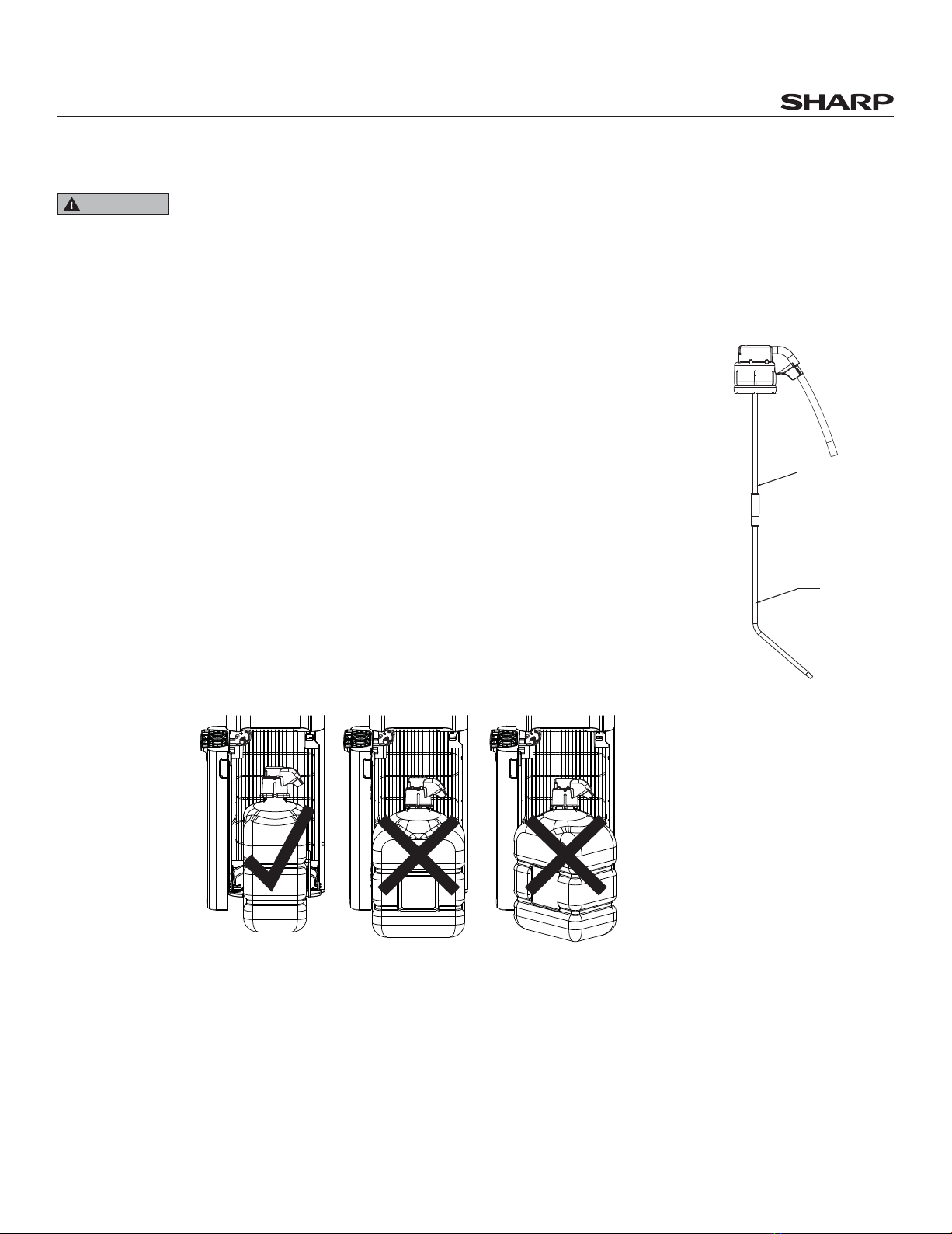
2. Set probe length.
• Adjust the length of the probe by pulling the B portion of the tube to its
proper length. Insert the probe into the bottle and push it down.
(See illustration on right)
3. Install bottle.
• Open door and place fresh bottle in front of tray.
• Clean fresh bottle with a soft cloth and warm soapy water then inse.
• Remove entire plastic cap from top of bottle.
• Insert probe into bottle.
• Push down on probe until it is seated.
NOTICE: When using a 5 gallon rectangular bottle, slide into place as shown in llustration below.
4. Plug cord into a properly grounded wall outlet.
• Water will be pumped into hot and cold water reservoirs from the bottle.
5. Turn energy saving switches on back of dispenser to ON.
• The red switch controls the heating of water. If you do not want hot water, leave this switch OFF
• The blue switch controls the cooling of water. If you do not want cold water, leave this switch OFF.
Notice:
• It will take up to 3 minutes for the reservoirs to load.
• Diring the use pump will come on to refill the tanks ,This is normal.
WARNING
Initial Rinsing of Water Lines
This unit has been tested and sanitized prior to packing and shipping. During transit
dust and odors can accumulate in the tank and lines. fill with water.wait for 30 minutes,Dispense
classes of hot water and 6 glasses of cold water.
Dispense Cold Water
Note: After setup, it will take 2 hour to get water to maximum cold temperature. During this
time the compressor may run continuously. This is normal.
1. Position bottle, glass, pitcher or cooking pot securely below cold water tap.
• The right triangle below the cold water control indicates the location of the cold water tap.
• The circular shapes in the drip plate help align the flow of water. This unit dispenses
water at a fast rate. To avoid splashes, hold cup as close to the tap as possible.
2. Depress right control downward to start flow.
3. Release control once desired fill level is achieved.
Dispense Hot Water
This unit dispenses water at temperatures that can cause severe burns. Avoid direct contact
with hot water. Keep children and pets away from unit while dispensing. Never allow children
to dispense hot water without proper and direct supervision.
Note: After setup, hot water will be available in 15-20 minutes.
1. Position bottle, glass, pitcher or cooking pot securely below hot water tap.
• The left triangle below the hot water control indicates the location of the hot water tap.
• The circular shapes in the drip plate help align the flow of water. This unit dispenses water at a
fast rate. To avoid splashes, hold cup as close to the tap as possible.
2. Push hot water release button (red) inward and depress control downward to start flow.
3. Release control once desired fill level is achieved.
Replace an Empty Bottle
Notice: When your bottle is empty the dispenser will beep intermittently and the LED nightlights will
blink until a fresh bottle is connected.
You may also hear a sucking sound when the bottle empties. This is normal and is another way to be
alerted that your bottle is empty.
Replace empty bottle as soon as you notice it is empty. If unavailable, leave door ajar or unplug cooler
to stop beeping noise and flashing lights.
There may be a small amount of water left in the bottle. This is normal, if you need assistance please
contact customer service.
1. Open door and slide bottle out.
2. Remove probe from bottle:
• Pull probe straight up until completely out of bottle.
•hang probe on the door.
3. Install fresh bottle:
• Place fresh bottle in front of tray.
• Clean fresh bottle with a soft cloth and warm soapy water then wepe with clean wet colth.
• Remove entire plastic cap from top of bottle.
• Insert probe into bottle.
• Push down on probe until it is seated.
• Slide bottle onto tray and close door completely.
6. Precautions
To reduce risk of injury and property damage, user must read this entire manual before assembling,
installing & operating dispenser.
Failure to execute the instructions in this manual can cause personal injury or property damage.
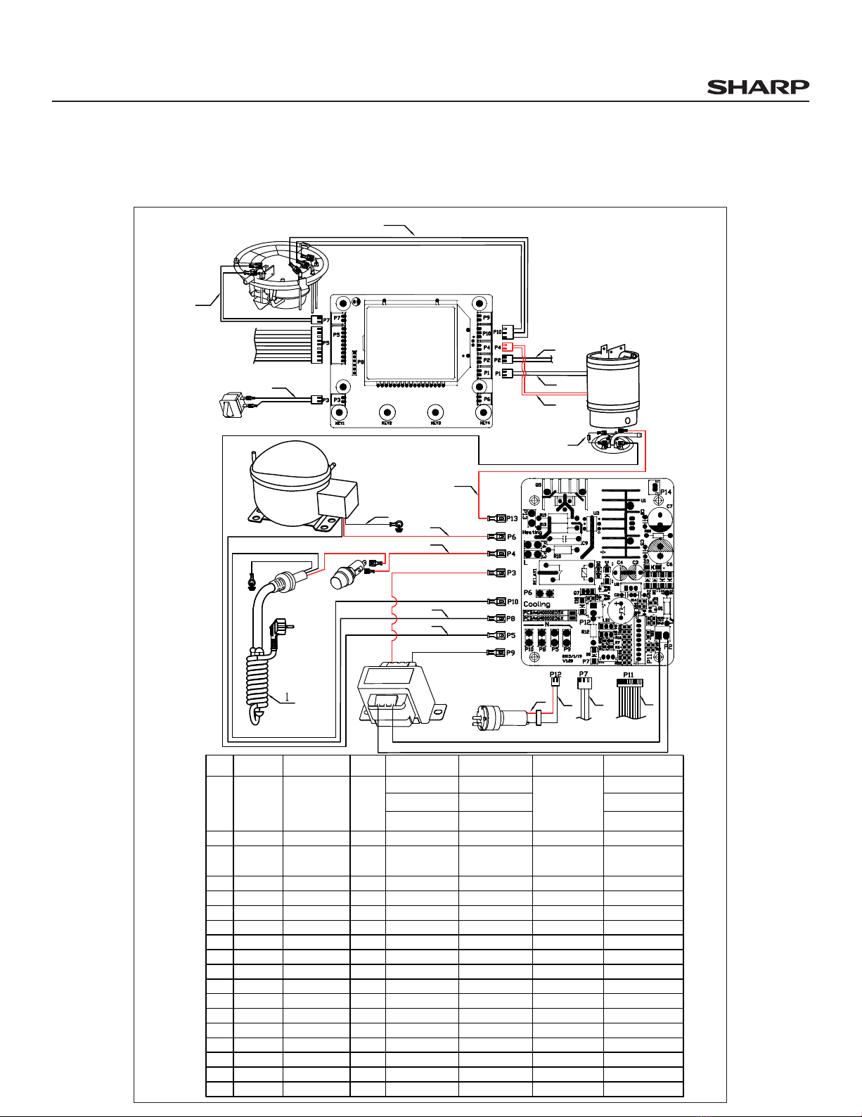
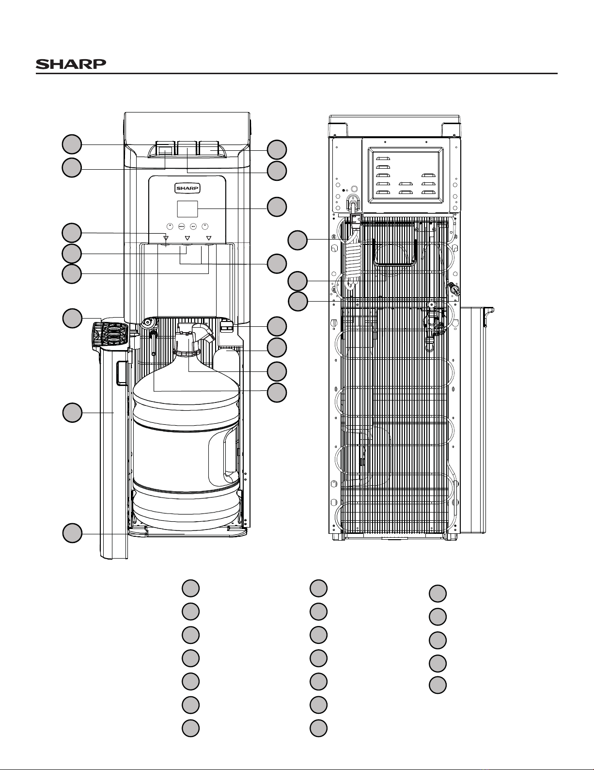
7. Assembly drawing and part list
This product dispenses water at very high temperatures. Failure to use properly can cause
personal injury.
When operating this dispenser, always exercise basic safety precautions, including the
following:
• Prior to use, this dispenser must be properly assembled and installed in accordance with this manual.
• This dispenser is intended for water dispensing only. Do NOT use other liquids. Do NOT use for other
purposes. Never use any other liquid in the dispenser other than known and microbiologically safe
bottled water. Warranty is void if used for any other liquids including coffee, tea, juices, beer or wine.
• For indoor use only. Keep water dispenser in a dry place away from direct sunlight. Do NOT use
outdoors.
• Install and use only on a hard, flat and level surface.
• Do NOT place dispenser into an enclosed space or cabinet.
• Do NOT operate dispenser in the presence of explosive fumes.
• Position back of dispenser no closer than 4 inches from wall and permit free airflow between wall and
dispenser. There must be at least 4 inches clearance on the sides of the dispenser to permit airflow.
• Use only properly grounded outlets.
• Do not use an extension cord with your water dispenser.
• Always grasp plug and pull straight out from outlet. Never unplug by pulling on power cord.
• Do NOT use dispenser if cord becomes frayed or otherwise damaged.
• To protect against electric shock, do NOT immerse cord, plug, or any other part of cooler in water or
other liquids.
• Ensure dispenser is unplugged prior to cleaning.
• Never allow children to dispense hot water without proper and direct supervision. Unplug unit to
prevent unsupervised use by children.