3
any liability for improper installation, maintenance and repair of any Cedarshed product.
Customers agree to hold Cedarshed Industries (1992) Inc. and any Authorized Dealers free of
your experience may differ from those presented in this manual, in our catalogue or on our website.
construction abilities and other factors may affect the construction of any Cedarshed product, so it is possible that
Our customers love telling us their Cedarshed stories and we are proud to hear them. Local conditions, personal
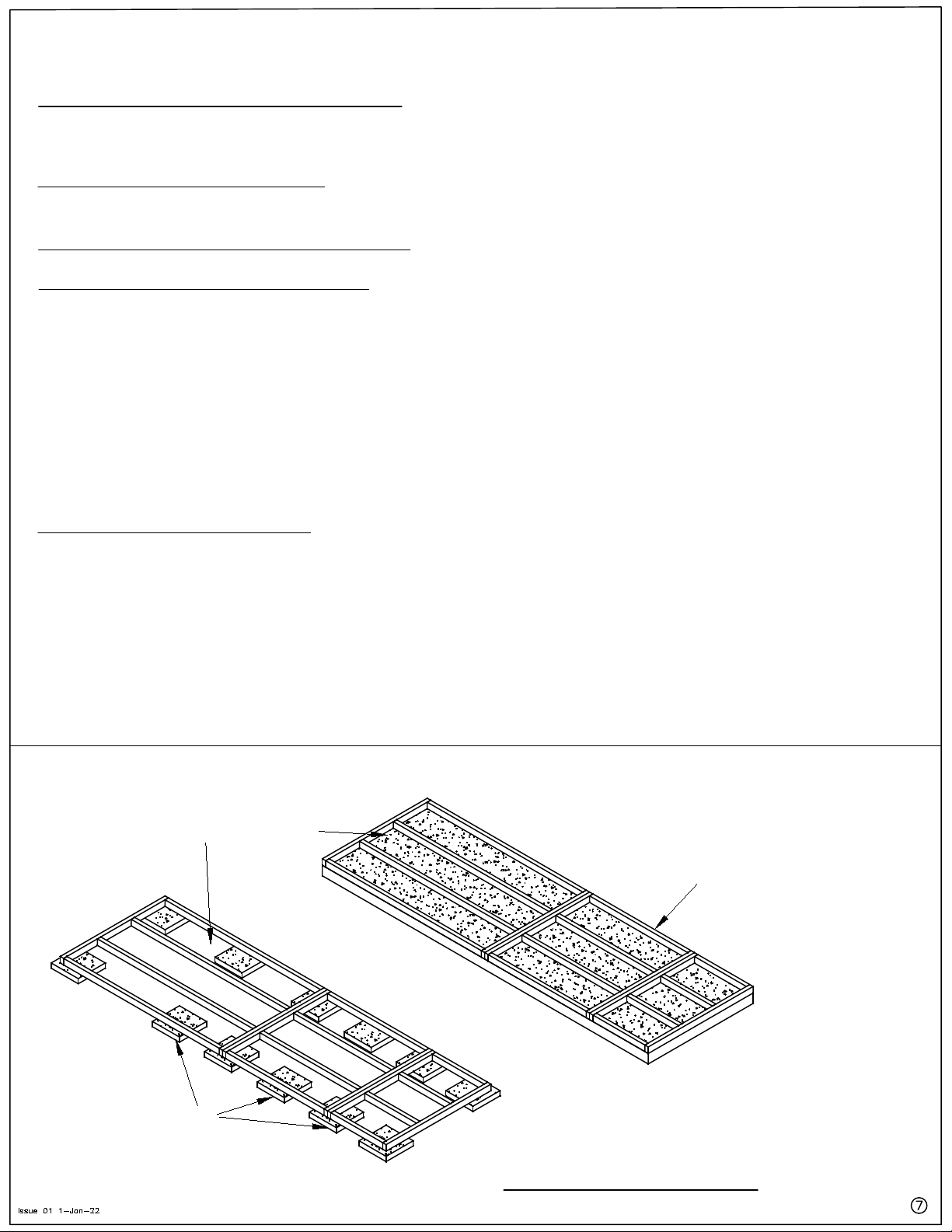
with knowledge on properly preparing a foundation.
Please review the information in this Assembly Manual or our web site or alternatively, consult with a professional
It is important to properly prepare the foundation to ensure the proper construction of Cedarshed products.
if this is the intended use.
In some geographical regions, our products are not rated for human occupancy. Please check with local authorities
ready for adverse weather conditions.
Have a regular maintenance plan to ensure floors, walls, doors, windows, roofing members etc. are secure and
structure securely grounded
In high or gusty wind conditions it is advisable not to use the structure, and it may be advisable to keep the
should be abided by.
If the structure is elevated above ground, local Building Code requirements are solely the owners responsibility, and
snow off the roof.
Roof Snow Load Ratings vary by geographical location. If a heavy or wet snowfall occurs, it is advisable to clear the
Some Safety Tips to Consider Include:
reference for future maintenance.
residential use. Please follow the Assembly Manual when building the structure, and keep this manual as a
many years to come. Our products are built for use based on proper installation on level ground and normal
As a proud owner of a Cedarshed gazebo, garden shed or outdoor furnishing(s), we want you to safely enjoy it for
Safety Points and Other Considerations
2" x 3" size. Wall and corner posts consist of 2" x 3"s. Floor framing 2" x 4".
All Cedarshed products are constructed of Western Red Cedar. All framing components are a nominal
recommended by the manufacturer. Always use appropriate safety equipment, including eye protection.
When using power tools, ladders or any other tool, observe all safety precautions
Obtaining necessary permits is the sole responsibility of the purchaser.
do not require building permits. If a permit is required, your local permit office will have an application form.
Check with your local permit office for the regulations for your area. Generally, structures under 100 square feet
6.
5.
4.
3.
2.
1.
Do I Need A Building Permit?
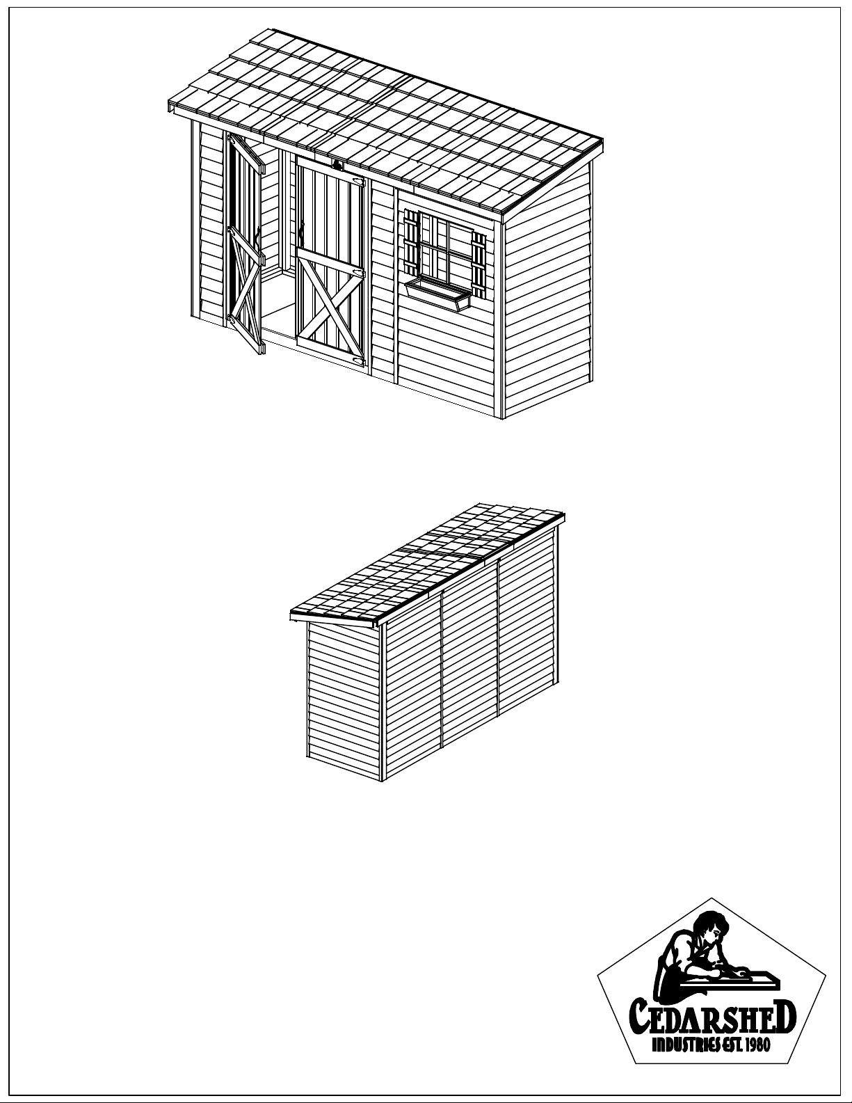
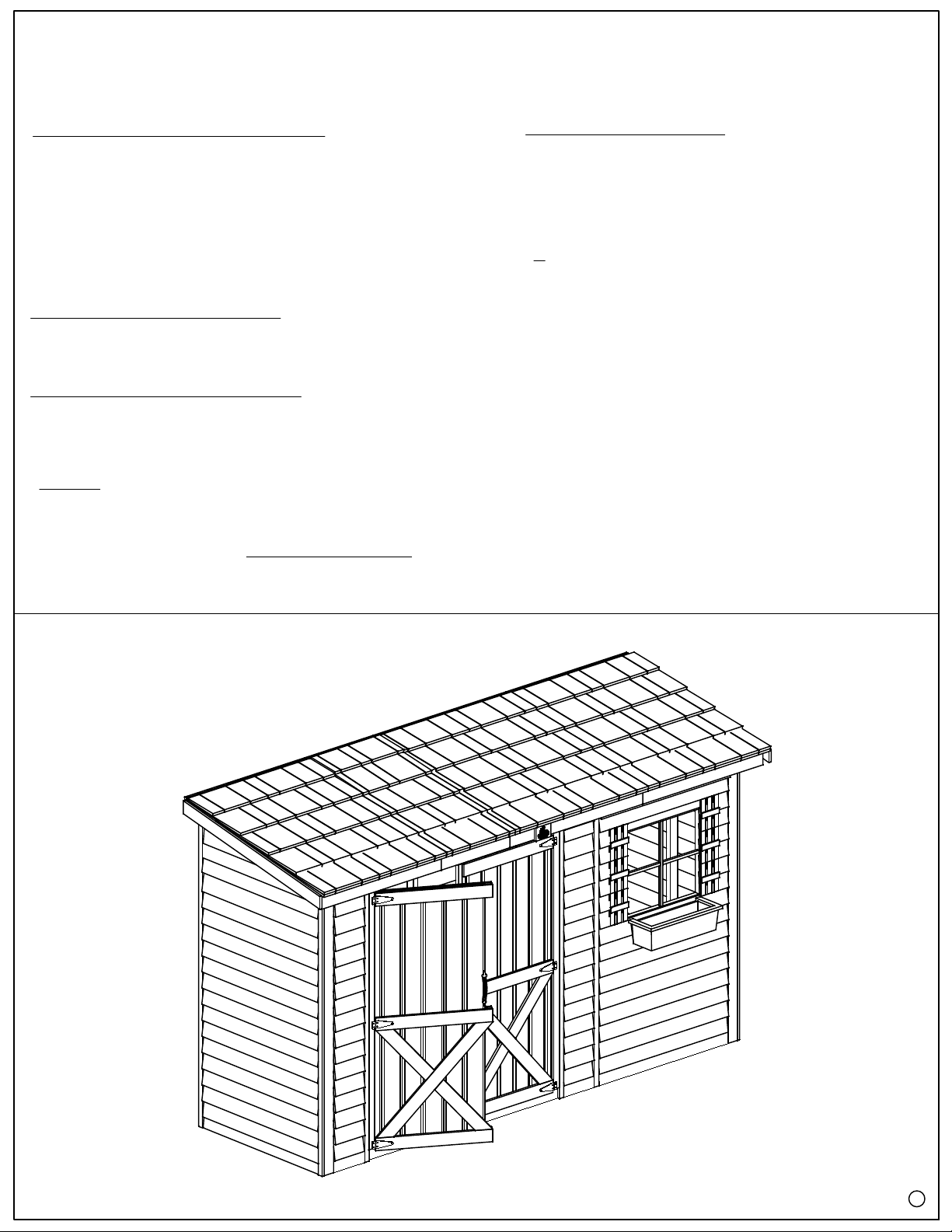
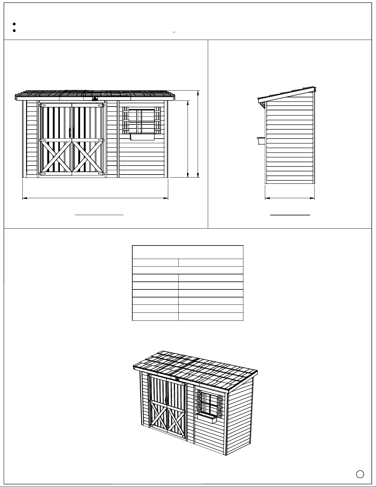
'The 12 x 4 Bayside'
B124DD
Issue 01 1-Jan-22