CEFLA RX DC User manual

X-ray unit
RX DC
Stabilimento / Plant
Via Bicocca 14/c - 40026 Imola (Bo) Italy
Tel. (+39) 0542 653441 - Fax (+39) 0542 653555
www.ceadentale.it - ceadentale@cea.it
Technical manual
Cod. 97071107 rev. 5
After Sales Service - Plant Via Bicocca 14/c 40026 Imola (BO)
Italy - Tel. +39 0542 653742 - Fax +39 0542 653596

1
GB INSTALLATION
RX DC X-RAY UNIT
Contents
1. General safety precautions.......................................................................................................................................3
2. Packaging.................................................................................................................................................................3
2.1. Dimensions and contents................................................................................................................................3
2.2. Handling and storage......................................................................................................................................3
3. Before installation....................................................................................................................................................4
3.1. Mechanical specications required .................................................................................................................4
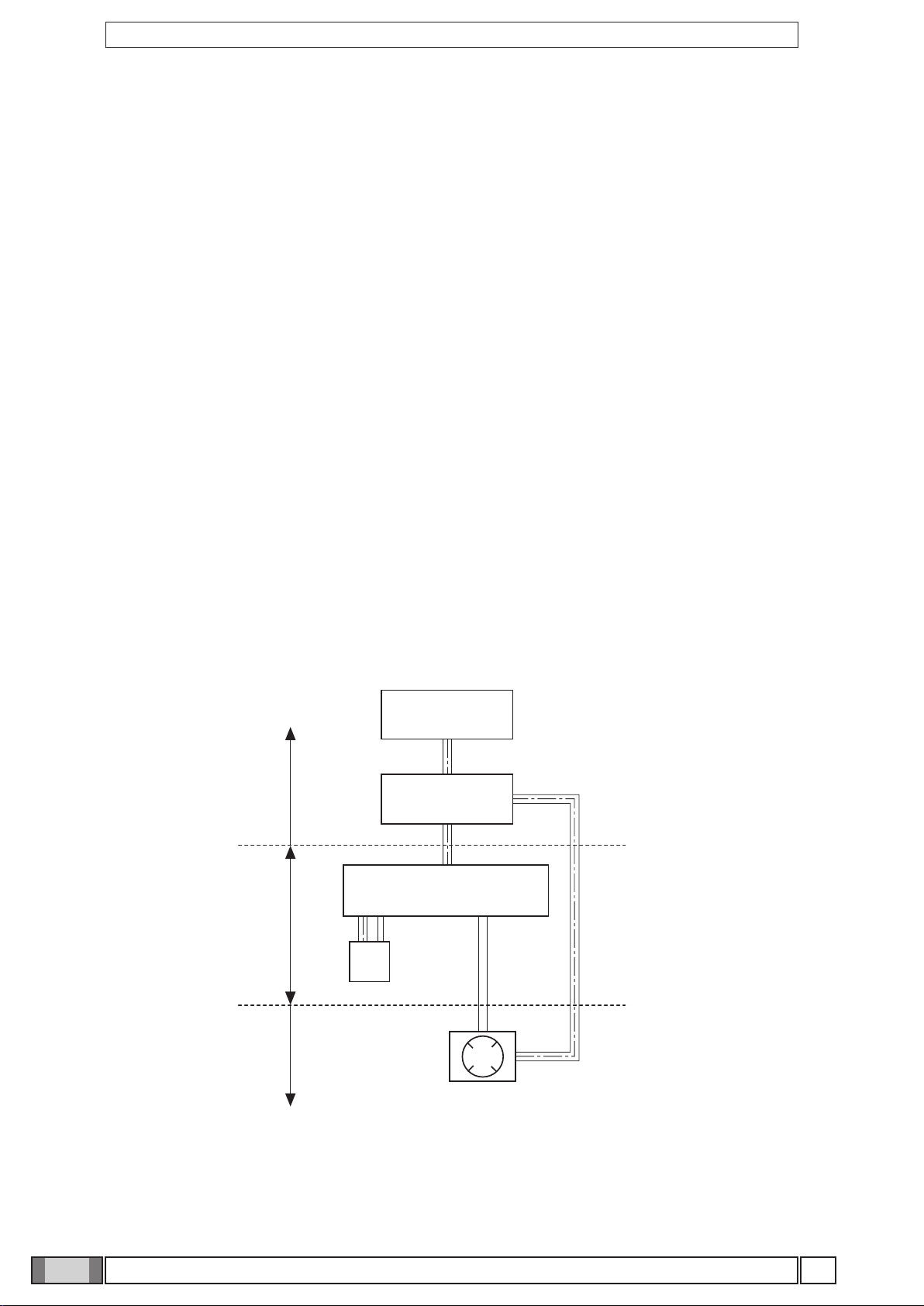
3.2. Central control unit power supply ...................................................................................................................4
3.3. Wiring connection between central control unit and generator light ..............................................................4
4. Installation ................................................................................................................................................................5
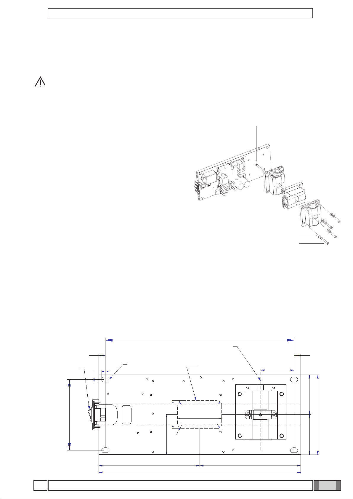
4.1. Positioning the x-ray unit’s structure ...............................................................................................................5
4.2. Wall-mounted plate for supporting the x-ray unit ............................................................................................5
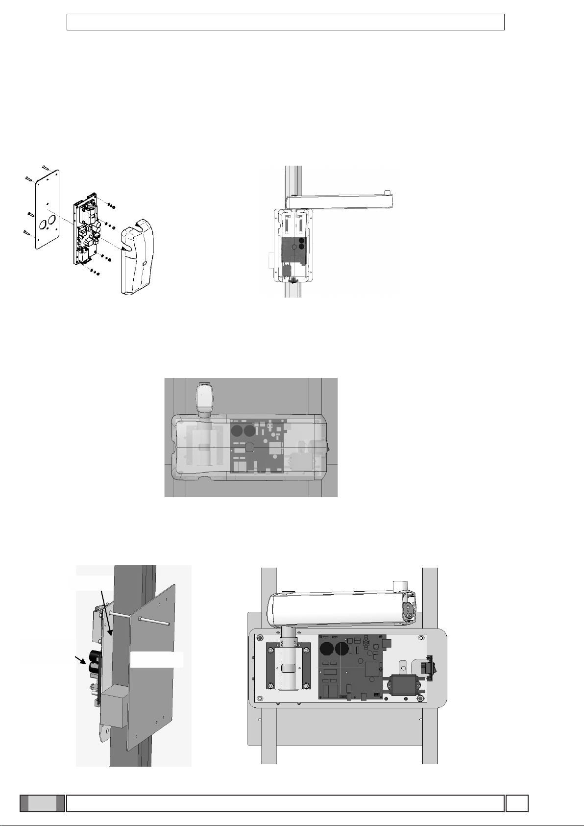
4.2.1. Vertical SINGLE STUD installation with wooden post ......................................................................6
4.2.2. Horizontal SINGLE STUD installation with wooden post...................................................................6
4.2.3. Vertical SINGLE STUD installation with iron post .............................................................................6
4.3. Extension arm .................................................................................................................................................7
4.3.1. PASS THROUGH installation extension arm......................................................................................8
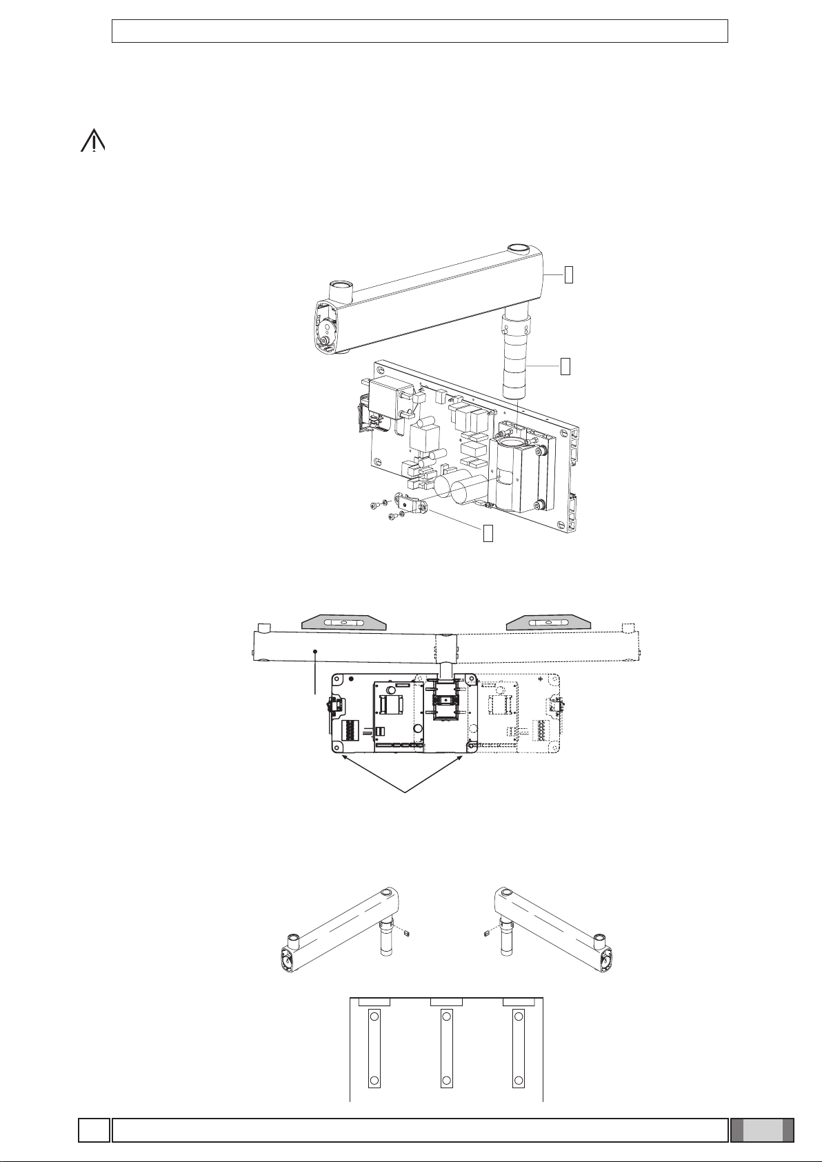
4.4. Installing the double pantograph arm .............................................................................................................9
4.5. Installing the RX DC with "ball end socket joint" generator........................................................................... 11
4.6. Installing the RX DC with standard joint generator ....................................................................................... 11
4.7. Installing the collimator .................................................................................................................................14
4.8. Balancing the double pantograph arm ..........................................................................................................15
4.9. Adjusting the double pantograph arm end-stops ..........................................................................................15
4.10. Wall-mounted plate wiring connections.......................................................................................................16
4.11. Completion of wall-mounting plate and holder for hand-held. ....................................................................17
5. Factory settings ......................................................................................................................................................18
6. Turning on...............................................................................................................................................................18
6.1. Turning The X-ray equipment on and off.......................................................................................................18
6.1.1. Turning on the basic X-ray unit........................................................................................................18
6.1.2. Turning on the handheld...................................................................................................................19
6.1.3. Control panel ....................................................................................................................................19
6.1.4. Automatic handheld shut off .............................................................................................................20
6.1.5. Hand-held stand-by time ..................................................................................................................20
6.1.6. Checking the set parameters ..........................................................................................................21
6.1.7. Factory settings ................................................................................................................................22
7. Batteries and charge level indication .....................................................................................................................22
8. X-ray generator indicator light ................................................................................................................................22
9. Position of the patient............................................................................................................................................23
10. Putting the x-ray unit cone into the required position .........................................................................................23
11. Position of the X-ray plate or sensor....................................................................................................................24
12. Checking the exposure time on the display.........................................................................................................25
12.1. Setting the exposure mode and time .........................................................................................................25
12.2. Setting the mode and exposure time in USER mode .................................................................................26
13 Procedure to be followed when taking the x-ray...................................................................................................27
14. Technician and user setup menu .........................................................................................................................28
14.1. Setting the safety unlock mode ..................................................................................................................29
14.2. Setting the operating mode ........................................................................................................................29
14.3. Setting the type of movable collimator .......................................................................................................29
14.4. Restoring factory settings ..........................................................................................................................29
14.5. Calibrating the X-ray head .........................................................................................................................30
15. Actuator unit (only RX DC with "ball end socket joint").........................................................................................31
16. Control unit card Code 97660515.........................................................................................................................32

2GB
INSTALLATION
RX DC X-RAY UNIT
17. Basic head control card Code 97660514 .............................................................................................................33
18. Actuator control card Code 97660591..................................................................................................................37
19. X-ray head............................................................................................................................................................38
19.1. Replacing the SLIP RING assembly (only RX DC with "ball end socket joint") ..........................................40
19.2. Check occupation of radiofrequencies for RXDC PDA ..............................................................................42
19.3 How to disable the channels that are excessively noisy. .............................................................................43
20. RX DC with "ball end socket joint" / With standard joint - INSTALLATION CHECK LIST FOR USA ONLY .....47
with "ball end socket joint" generator..........................................................................................................47

3
GB INSTALLATION
RX DC X-RAY UNIT
1. General safety precautions
Cea Sc - Cea Dental Group guarantees the safety, reliability and performance of the equipment under the following
conditions:
- Installation and technical service is performed by authorized technicians using Cea Sc - Cea Dental Group original
spare parts.
- The electrical system in the dental surgery corresponds to standards I.E.C. 60364-7-710;V2 (Standards regarding
electrical systems in a medical environment) or equivalent standards currently in force in the country where the equi-
pment is installed.
- The place where the x-ray unit is installed must comply with ofcial directives regulating radiation in the country where
the equipment is used.
- The equipment is operated as directed in the instructions manual..
This device complies with part 15 of the FCC Rules. Operation is subject to the following two conditions: (1) This device
may not cause harmful interference, and (2) this device must accept any interference received, including interference
that may cause undesired operation.
This equipment has been tested and found to comply with the limits for a Class B digital device, pursuant to part 15 of
the FCC rules. These limits are designed to provide reasonable protection against harmful interference in a residential
installation. This equipment generates, uses and can radiate radio frequency energy and, if not installed and used in
accordance with the instructions, may cause harmful interference to radio communications
Changes or modications not expressly approved by the party responsible for compliance could void the user’s autho-
rity to operate the equipment.
2. Packaging
2.1. Dimensions and contents
•DIMENSIONS:103X53X36CM
•WEIGHT:38KG
•CONTENTS:
- Documentation and guarantee
- Disposable jig for installation
- Kit
- Wall back-plate (if requested)
- Wall-mounted plate
- Generator
- Tube
- Extension
- Collimator
- Double pantograph arm
2.2.Handlingandstorage
Indications regarding storage, handling and unpacking are given on the outside of the
cardboard packaging.
These indications must be strictly observed.
1) The package must be kept upright in the direction indicated by the arrows at all times
during handling and storage.
2) Avoid banging the package.
3) Keep the package free from damp.
4) Do not use hooks to handle the package.
5) A nameplate indicates the required ambient conditions for storage.
a) temperature from -15° to 50° C.
b) relative humidity from 10 to 90%
c) atmospheric pressure from 500 to 1060 hPa.

4
a
b
c
d
e
f
GB
INSTALLATION
RX DC X-RAY UNIT
3.Beforeinstallation
3.1.Mechanicalspecicationsrequired
If the wall is thin (hollow bricks or similar), use the backplate (part no. 9660048) to be mounted on the wall or placed on
the side of the wall opposite the wall where the unit is to be installed.
Decide on a suitable system for xing the plate according to the characteristics of the wall and its ability to resist a pull
force of 220 Kg applied at each anchorage point.
If the wall is made of cement or solid bricks, use the wall plugs supplied.
Alternativelywerecommendusingthe“FISHER”chemicalwallplugswhichinclude:
•Braidtypeinjectioninsert(itemFIP16X85).
•Threadedbarwithbarandwasher(itemFIP16M,8X110).
•Chemicalxer(itemFIPC150).
3.2.Centralcontrolunitpowersupply
The supply line running to the central control unit must be 3x2.5 mm and protected by a bipolar circuit breaker which
conforms to the relevant electrical codes (10 A, 250 V, breaking power at least 6000 A, distance between contacts at
least 3 mm).
The colour of the three conductors (LINE, NEUTRAL and GROUND) must correspond to that established by regula-
tions.
3.3.Wiringconnectionbetweencentralcontrolunitandgeneratorlight
This connection enables the generator light (optional) located outside the surgery to be turned on.
To connect the LP generator light to the central control unit, use 2 conductors having a cross-section of 0.5 mm (see
paragraph 4.8.).
LP light supply: 230V - 3x2.5 mm line.
Legenda:
a) SUPPLY LINE
b) CIRCUIT BREAKER 10 A
c) CENTRAL CONTROL UNIT
d) OPTIONAL
e) SUPPLIED
f) NOT SUPPLIED

5
SCATOLA ALLACCIAMENTI
A
MURO
ASSE BRACCIO
RADIOGRAFIC
O
POSIZIONE FISSAGGI
A
MURO
INTERRUTTOR
E
GENERAL
E
152.5
406.4
71.7
435
217.5 217.5
172
85.5
86.5
16
11
14.3
14.3
60
95
R10
R 10
R 10
R 10
86
GB INSTALLATION
RX DC X-RAY UNIT
4. Installation
The x-ray unit must be installed by a qualied technician in compliance with the installation instructions given below as
regards both the mechanical and electrical parts.
WARNING!
Alwayscheckthatthevoltageindicatedonthegenerator’snameplatecorrespondstothatfortheelectrical
system.
Figure A
Figure POSITIONING
4.2.Wall-mountedplateforsupportingthex-rayunit
FigureA
• Determine the position of the x-ray unit by using the INSTALLATION JIG.(code 97042058).
• First check that the plate is at the correct height and perfectly horizontal and then mark out the four points where it is to be
xed on the wall. Drill the holes and install the most suitable type of fastening system according to the characteristics of the
wall (see paragraph 3.1).
• Pass the supply cable through one of the holes in the wall-mount plate and x this to the wall by partially tightening the
top and bottom screws.
MAIN
SWITCH
LOCATION
WALL
FIXING
AXLE
RADIOLOGIC
ARM
WALL BOX
CONNECTIONS
4.1.Positioningthex-rayunit’sstructure
FigurePOSITIONING
• Block the middle clamp in the opening provided (d) according
to which of the three positions available the structure needs
to be placed in:
A–PRESETCONFIGURATIONWITHWALL-MOUNTED
STRUCTURESETHORIZONTALLYTOTHERIGHT.
B-WALL-MOUNTEDSTRUCTURESETVERTICALLY
DOWNWARD.
C-WALL-MOUNTEDSTRUCTURESETHORIZONTALLYTO
THELEFT.
• Secure the pin to the plate using the srews (f) and washers (e)
provided.

6GB
INSTALLATION
RX DC X-RAY UNIT
4.2.1.VerticalSINGLESTUDinstallationwithwoodenpost
• Insert the 4 TPSEI M8x35 screws with heads that allow them to be driven with a screw driver provided in the interface plate
• Run the power cord through one of the holes in the interface plate
• Attach the interface plate to the wooden post with no. 3 dia. 3/8'' x L 3'' wood screws (not supplied)
• Attach the x-ray unit’s wall-mounting plate to the interface plate by tightening the washers and nuts provided on the
TPSEI M8x35 screws with heads that allow them to be driven with a screw driver
4.2.2.HorizontalSINGLESTUDinstallationwithwoodenpost
The interface plate is not needed for 1.5'' wooden posts with 16'' spacing. Simply attach the RX-DC plate with no. 4 dia.
3/8'' x L 3'' wood screws (not supplied)
4.2.3.VerticalSINGLESTUDinstallationwithironpost
• Attach the wall-mount counter-plate to the iron posts (not completely seen) with the threaded bars and screws provided
• Attach the interface plate to the counter-plate. Secure the x-ray unit’s wall-mounting plate to the latter
Contropiastr
a
murale
Piastra di
interfaccia
Piastra
murale RX
Interface
plate
RX
wall-mounting
plate Counter-plate

7
GB INSTALLATION
RX DC X-RAY UNIT
4.3.Extensionarm
WARNING!
Donotlubricatethepinoftheextensionarm:thewall-mountedplateisprovidedwithself-lubricatingbushings.
FigureB
• Insert the pin (b) of the extension arm (c) in the hole provided in the wall-mounted plate.
• Take the clutch (a) from the kit, install it on the plate using the corresponding screws and adjust the arm (c) as requi-
red.
FigureC
• Use a spirit level to check that the arm (c) is slightly tilted upwards (approx. 1°). If necessary add a shim to the plate
near the bottom wall plugs (d).
• Fully secure the plate.
FigureD
• If the x-ray unit is installed in one of the corners of the dental surgery, make sure the extension arm cannot rotate too
far (90°) by installing the two end-stop pins (included in the kit) on the x-ray unit itself.
• Find the right position for installing the pair of pins (a,b) and insert them in the holes provided using a hammer.
Figure B
Figure C
Figure D

8GB
INSTALLATION
RX DC X-RAY UNIT
4.3.1.PASSTHROUGHinstallationextensionarm
Install inside cabinet model PXTG92 42.5'' x 49''
Switch at top h=191cm
Check the direction of the pin support: it should be set as shown in gure (A) for this type of installation.
Insert the extension arm pin in the hole in the wall-mounting plate from below. Place the washer supplied on top of
the pin and forcefully tighten the ring nut with the pin spanner provided, as shown in the gure (B).
Install the clutch (a) as directed in paragraph 4.3 gure (B) .
Fig. A Fig. B

9
GB INSTALLATION
RX DC X-RAY UNIT
4.4.Installingthedoublepantographarm
WARNING!
Thearmsaresuppliedsecuredtogetherbyabelt.
Thisbeltshouldnotberemoveduntilthetwofreeendsofthearmshavebeenconnectedtotheircorresponding
attachments:theextensionarm(alreadysecuredtothewall)andx-rayhead.
Ifthebeltisloosenedbeforexingthearmsinplace,releasingthemabruptlycoulddamagethemandthe
operatorrisksbeinginjured.
FigureE
• Take the washer (f) from the kit and position it at point (i) corresponding to the extension arm (c).
• Pass the cable (m) of the pantograph arm (e) through the extension arm (c) so that it comes out of the hole below.
• Install the pantograph arm (e) on the extension arm (c)
NOTE:
Theextensionarm’sbushingisself-lubricating.
Donotlubricatethepinofthedouble-pantographarm.
• Pass the cable (m) through the inside of the extension arm (c) so that it comes out of the wall-mounted plate.
• Install the plugs (g) in the corresponding holes in the extension arm (c).
Figure E

10
GB
INSTALLATION
RX DC X-RAY UNIT
FigureF
• Take the grubscrew used to stop rotation (o) from the x-ray unit kit and tighten it at point H (tighten it fully and then
loosen by ½ turn).
NOTE:Turnthepantographarmtocheckthattheadjustmenthasbeenmadeproperly.
• Take the clutch assembly (friction element, screw and 4 curved washers) from the x-ray unit kit and install it at point
L.
NOTE: Insertthecurvedwashers(j)andthefrictionelement(k)asindicatedingureF.
NOTE: Thefrictionelement(k)canbeplacedinthecorrectposition(verticalcut)byinsertingascrewdri-
verintheholeprovidedforthescrew(n).
FigureG
• Adjust the clutch which has just been installed.
NOTE:Turnthepantographarmduringtheadjustmenttocheckthattheclutchisprovidingthecorrect
amount of friction.
• Install the plugs (p) on the extension arm (c).
• Attach the adhesive bumper (q) (supplied in the kit) in the centre of the plug at the point indicated in the diagram.
FigureH
• There are 2 end-stop screws in the wall-mounted plate to which Loctite has been applied to provide friction. These
have been adjusted according to the length of the extension arm supplied.
NOTE:Workonthescrewitself(a)inordertomaketheextensionarmstopbeforeorafter.
Figure F
Figure G
Figure H

11
GB INSTALLATION
RX DC X-RAY UNIT
4.5.InstallingtheRXDCwith"ballendsocketjoint"generator
FigureI
• Take the generator out of the packaging.
• Insert the pin (a) in the sleeve making sure the respective openings match and secure with the screws (b) provided.
• Insert the power cable in the generator’s pin and run it out of the opening (c) provided.
• Lastly, put on the two side covers montare (d).
4.6.InstallingtheRXDCwithstandardjointgenerator
- Take the generator out of its packaging.
- Lubricate the bush of the pantograph arm and the generator pivot point with grease designed for bearings. (FIAT MR3).
Figure J
Figure I

12 GB
INSTALLATION
RX DC X-RAY UNIT
- Take the washer (a) from the kit supplied and t it in the pin (b) with the protruding tooth (c) pointed towards the right-
hand head. (see g.K)
Positiontheprotrudingtooth(c)ofthewasher(a)inzone1ofthepin(b).(seeg.L)
WARNING!DONOTpositiontheprotrudingtooth(c)ofthewasher(a)inzone2ofthepin(b).
- Insert the power supply cable of the pantograph arm in the generator pin until it comes out of the hole below (see
point c – g. M).
- Raise the cover (a).
- Insert the pin in the sleeve so that it corresponds to the openings provided and then Fit the mounting yoke (d) sup-
plied.
- Lower the cover (a) so that the hole (f) in the cover (a) is aligned with the hole in the internal washer (e).
- Fit the M4x6 self-locking grub screw (g) into the hole (f) and tighten it to 1 mm below the outer surface of the cover
(a).
Figure K
Figure L

13
GB INSTALLATION
RX DC X-RAY UNIT
Figure M
Figure N
- Fit the connector of the pantograph arm cable to that of the generator cable.
- Place them inside the hole provided (c).
- Fit the plug (e) supplied into the hole then tighten the screw that is already in place. (see g. N)

14
GB
INSTALLATION
RX DC X-RAY UNIT
Figure O
Figure P
4.7.Installingthecollimator
- Take the collimator out of the packaging:
round in case of RX DC with standard joint
round or rectangular in the case of RX DC with "ball end socket joint"
- Insert it in the generator and block it in place by turning clockwise.

15
GB INSTALLATION
RX DC X-RAY UNIT
4.8.Balancingthedoublepantographarm
FigureQ
If the double pantograph arm does not stay in a stable position, adjust the spring tension by using an 8mm Allen wrench
about 20cm long.
• To adjust the arm (a) connected to the extension: position it as shown in the gure and place the wrench at point A.
NOTE:
TIGHTEN(clockwise)ifthearmtendstomovedown.
LOOSEN(anti-clockwise)ifthearmtendstomoveup.
• To adjust the arm (b) connected to the generator: put the 2 covers (c) and (d) on the front pivot point, move the arm
(b) into a horizontal position and insert the key in point B.
NOTE:
TIGHTEN(clockwise)ifthearmtendstomovedown.
LOOSEN(anti-clockwise)ifthearmtendstomoveup.
4.9.Adjustingthedoublepantographarmend-stops
FigureR
If the end-stops of the double pantograph arm need to be adjusted, work on the screws (i -l - m - n)shown in the
diagram.
NOTE:
To adjust the screw (n) on the articulated joint of the extension side place the relevant arm (a) in a horizontal position.
Figure Q
Figure R

16
K5
K2
K3
230V
115V
GB
INSTALLATION
RX DC X-RAY UNIT
4.10.Wall-mountedplatewiringconnections
FigureS
• Connect the power cable (LINE) to terminal K2, observing the following positions:
L - SUPPLY (BROWNWIRE)
- GROUND (YELLOW/GREENwire)
N - NEUTRAL (BLUEwire)
• Connect the generator’s power cable to the respective connectors, observing the following positions:
K6 - brown wire and blue wire.
K5 - whitewire–blackwire–redwire–greenwire–purplewire.
Eyelet connectors - Both found near the card (see gure).
NOTE:Placetheexcesscableunderthecard.
• Connect the 2 control wires (0.5 mm cross-section) for the “generator on” indicator light (LP) to connector K3.
Figure S

17
GB INSTALLATION
RX DC X-RAY UNIT
4.11. Completionofwall-mountingplateandholderforhand-held.
FigureTandFigureU
• Pick up the cover (a) and place it over the wall-mounting plate fully tightening the grub screws (b) provided and pre-
screwed on the plate.
• Place the cover (c) in the area shown in the gure. The door (d) will automatically close when the controller is clo-
sed.
• Put the controller label in the required area (e) on the cover directed according to the position in which he wall-moun-
ting plate is installed.
• To install the handheld’s mount (f), refer to the INSTALLATION TEMPLATES.
Figure T
Figure U

18
B
GB
INSTALLATION
RX DC X-RAY UNIT
5.Factorysettings
The x-ray unit is supplied with the following factory settings:
• Anode current: 6/7 mA (NORM mode).
• Sensitivty: level 19.
• Handheld stand by: 5 minutes
• Patient’s built: adult (ADULT symbol selected).
• Collimator presence signaled on the display (collimator symbol off if the rectangular collimator is turned on in the
head).
• Exposure times according to standard R20: 0,010-0,011-0,012-0,014-0,016-0,018-0,020-0,022-0,025-0,028-0,032-
0,036-0,040-0,045-0,050-0,056-0,063-0,071-0,080-0,090-0,100-0,110-0,125-0,140-0,160-0,180-0,200-0,220-0,250-
0,280-0,320-0,360-0,400-0,500-0,560-0,630-0,710-0,800-0,900-1,000.
NOTE:
ThesetimescomplywithcurrentstandardsI.E.C.60601-2-7(1999)andtheISO497seriesR’20recommendations
andCANNOTBEMODIFIED.
6.Turningon
6.1.TurningTheX-rayequipmentonandoff
6.1.1.TurningonthebasicX-rayunit
The control unit is turned on and off with the main switch (A), as illustrated in the gure below. The switch lights up
when the control unit is energized.
NOTE:Whenever turned on, the equipment performs an operational test that takes a few seconds. Once the
test has been completed, a buzzer rings and the indicator light (B) on the X-ray generator lights up at the same time.
NOTE:The exposure time and the parameters displayed when the unit is turned on are the last ones set before
the central control unit was turned off. If the central control unit is left untouched for a few minutes it will go into stand-by
mode. Simply press any key on the control panel to reactivate it.

19
GB INSTALLATION
RX DC X-RAY UNIT
6.1.2.Turningonthehandheld
The handheld is turned on by pressing any key, except for the one for x-ray emission. A buzzer rings to conrm the
apparatus has been turned on. The unit will be in the standard conguration described in detail in paragraph 5 and then
search for the base it works with.
If the base is off, the handheld will not indicate the eld nor status “ready”. If the base is latter turned on, the handheld
will detect it within thirty seconds or by pressing any function key on the pushbutton panel.
NOTE: To maximize the scope of the handheld during its use, you should keep it away from walls and metal
tools and above all do not cover the internal aerial at the top of the display in addition also too rapid movement of the
handheld during exposure may reduce the performance. If ow could appear on the display error is 31.
6.1.3.Controlpanel
As illustrated in the gure below, the handheld has four function keys and the exposure key.
Pause for
cooling
Field present for
dialoging with “base”
Tooth
selection
Exposure time
and dose display
Battery
charge level
Body build selection
Graduated bar for
thermal load
USER mode on
8” round collimator on (12”
rectangular collimator not
attached)
Time/dose unit of
measure
Handheld identica-
tion number
Possible to save
“Dentition area selection”
key
“Decrease” key
“X-ray emission” key
“Body build selection”
key
X-ray emission light
“Increase” key
Other manuals for RX DC
1
Table of contents
Other CEFLA Dental Equipment manuals