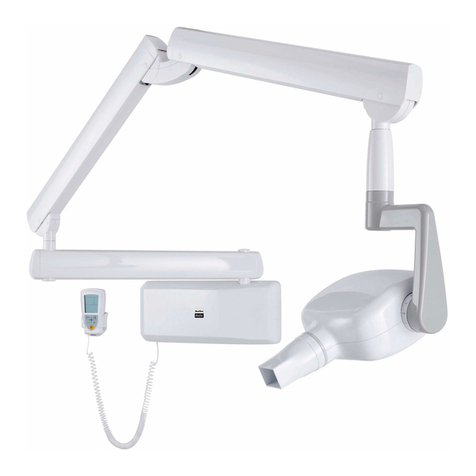
CEFLA RX DC User manual

cod. 97071214
rev. 05_18.12.2018
Stabilimento / Plant
Via Bicocca, 14/C - 40026 Imola (BO) - ITALY
Sede Legale ed Amministrativa / Headquarters
Cefla s.c. Via Selice Provinciale 23/A - 40026 Imola (BO) - ITALY
Supporto Tecnico / Technical Support
Tel.: (+39) 0542 653742 / 0542 653842
Fax: (+39) 0542 653596
RX DC Technical Manual


1
GB INSTALLATION
RX DC X-RAY UNIT
CONTENTS
1. GENERAL WARNINGS ......................................................................................................... 5
1.1 Foreword ........................................................................................................................................ 5
1.2 Safety instructions .......................................................................................................................... 5
2. PACKAGING........................................................................................................................... 6
2.1 Dimensions and contents ............................................................................................................... 6
2.2 Handling and storage ..................................................................................................................... 6
3. BEFORE INSTALLATION ..................................................................................................... 7
3.1 Environmental conditions ............................................................................................................... 7
3.2 Mechanical specications required................................................................................................. 7
3.3 Central control unit power supply .................................................................................................. 7
3.4 Wiring connection between central control unit and generator light ............................................. 8
4. INSTALLATION ...................................................................................................................... 9
4.1 Positioning the x-ray unit’s structure............................................................................................... 9
4.2 Wall-mounted plate for supporting the x-ray unit ............................................................................ 9
4.2.1 Vertical SINGLE STUD installation with wooden post ..................................................... 10
4.2.2 Horizontal SINGLE STUD installation with wooden post .................................................. 10
4.2.3 Vertical SINGLE STUD installation with iron post ............................................................ 10
4.3 Extension arm................................................................................................................................11
4.3.1 PASS THROUGH installation extension arm.................................................................... 12
4.4 Installing the trolley....................................................................................................................... 13
4.5 Installing the double pantograph arm .......................................................................................... 16
4.6 Installing the RX DC with "ball end socket joint" generator .......................................................... 18
4.7 Installing the RX DC with standard joint generator....................................................................... 18
4.8 Installing the collimator ................................................................................................................. 21
4.9 Balancing the double pantograph arm.......................................................................................... 22
4.10Adjusting the double pantograph arm end-stops.......................................................................... 22
4.11 Wall-mounted plate wiring connections ........................................................................................ 23

2GB
INSTALLATION
RX DC X-RAY UNIT
4.12Completion of wall-mounting plate and holder for handheld. ...................................................... 23
5. FACTORY SETTINGS.......................................................................................................... 26
6. TURNING ON AND FUNCTIONING OF THE DEVICE ..................................................... 26
6.1 Turning on the basic X-ray unit.................................................................................................... 26
6.2 Handheld Functions ..................................................................................................................... 27
6.3 Handheld display functions ......................................................................................................... 28
6.4 Use of handheld .......................................................................................................................... 29
6.5 X-RAY unit stand-by time.............................................................................................................. 30
6.6 Checking the parameters ............................................................................................................. 30
6.7 Factory settings ............................................................................................................................ 31
6.8 Positioning the X-ray head .......................................................................................................... 31
6.9 Position of the x-ray plate or sensor ............................................................................................. 32
6.10Procedure to be followed when taking the x-ray........................................................................... 33
7. TECHNICIAN AND USER SETUP MENU ......................................................................... 33
7.1 Setting the safety unlock mode .................................................................................................... 35
7.2 Setting the operating mode .......................................................................................................... 35
7.3 Setting the type of movable collimator ......................................................................................... 36
7.4 Calibrating the X-ray head ........................................................................................................... 36
8. ADJUSTING THE ACTUATOR UNIT (ONLY RX DC WITH "BALL END SOCKET
JOINT") ................................................................................................................................. 37
9. ELECTRONIC BOARDS...................................................................................................... 40
9.1 Power Board (Code 97661585).................................................................................................... 40
9.2 Basic X-ray head control card (Code 97661586) ........................................................................ 42
9.2.1 Replacing the basic X-ray head control card ................................................................... 44
10. X-RAY HEAD........................................................................................................................ 46
10.1Handheld unit-X-ray head association.......................................................................................... 46
10.2Setting the X-ray head in combination mode................................................................................ 47
10.3Send the recognition signal from the handheld unit to the X-ray head......................................... 47

3
GB INSTALLATION
RX DC X-RAY UNIT
10.4Inspections and modications of Wi-Fi parameters on RX unit .................................................... 47
10.4.1 Change Wi-Fi settings..................................................................................................... 48
10.4.2 Forcing the Wi-Fi channel through DIP switches ............................................................ 49
10.5 Replacing the SLIP RING assembly (only RX DC with "ball end socket joint")........................... 49
11. ERROR CODES GIVEN ON THE HANDHELD ................................................................ 51
12. FIRMWARE UPDATE PROCEDURE.................................................................................. 54
13. ELECTRIC WIRING DIAGRAMS........................................................................................ 58
13.1REF. **P*****S ............................................................................................................................. 58
13.2REF. **X*****S REF. **E*****S...................................................................................................... 59
13.3REF. **P*****I................................................................................................................................ 60
13.4REF. **P*****I................................................................................................................................ 61
13.5REF. **P*****M.............................................................................................................................. 62
13.6REF. **X*****M - REF. **E*****M .................................................................................................. 63
14. PERIODICAL MAINTENANCE ........................................................................................... 64
15. RX DC WITH "BALL END SOCKET JOINT" / WITH STANDARD JOINT -
INSTALLATION CHECK LIST (FOR USA ONLY)............................................................. 65

4GB
INSTALLATION
RX DC X-RAY UNIT

5
GB INSTALLATION
RX DC X-RAY UNIT
1. GENERAL WARNINGS
1.1 Foreword
The device described in this manual is manufactured by CEFLA s.c. - via Selice Prov.le 23/A - 40026 Imola (BO) Italy,
a manufacturer complying with the European Directive on medical devices 93/42/EC (Class 2, B).
These instructions are intended for all the personnel who service and/or repair the Cea s.c. equipments. All the spe-
cic information required is provided.
IMPORTANT READ CAREFULLY BEFORE USE
KEEP FOR FUTURE REFERENCE
1.2 Safety instructions
All the safety instructions that help prevent any hazardous situations and operate the equipment in a trouble-free man-
ner are given in the user’s manual as explained below:
WARNING: This alert symbol indicates that the users and/or the patients run high risks and can be seriously inju-
red if the equipment or certain devices are used incorrectly or improperly, or the recommended safety precautions
are not taken to avoid hazardous situations.
CAUTION: Indicates that the operator is to take all the required precautions in order for all devices and/or
equipment to be used safely and eciently.
When the equipment is received, check the packing container for any damage suered. If evident damage is found,
immediately call the shipping agents and le a claim for damage. Carefully inspect the equipment for any missing or
damaged parts. For any complaints, immediately contact Cea s.c..
Cea s.c. shall be responsible for the reliability and eciency of the equipment as well as the safety of the operating
personnel provided that:
• the installation, modications, settings or repairs are made by authorised persons using Cea s.c. original spare parts;
• the electrical wiring in the surgery complies with IEC 60364-7-710:2002 engineering regulations ( (Standards
regarding electrical systems in a medical environment) or equivalent standards currently in force in the country where
the equipment is installed).;
• the equipment is used as outlined in User’s Manual.
• the place where the x-ray unit is installed must comply with ocial directives regulating radiation in the country where
the equipment is used.

6
GB
INSTALLATION
RX DC X-RAY UNIT
2.2 Handling and storage
Indications regarding storage, handling and unpacking are given on the outside of the cardboard packaging.
These indications must be strictly observed.
1) The package must be kept upright in the direction indicated by the arrows at all times
during handling and storage.
2) Avoid banging the package.
3) Keep the package free from damp.
4) Do not use hooks to handle the package.
5) A nameplate indicates the required ambient conditions for storage.
a) temperature from -15° to 50° C.
b) relative humidity from 10 to 90%
c) atmospheric pressure from 500 to 1060 hPa.
MOBILE STAND INSTALLATION
• N° 2 PACKAGES Dimensions: 103x53x36 cm
• 1ST PACKAGE Weight: 38 kg
• Contents 1ST PACKAGE:
- Documentation and guarantee
- Disposable jig for installation
- Kit
- Wall back-plate (if requested)
- Wall-mounted plate
- Generator
- Tube
- Extension
- Collimator
- Double pantograph arm
• 2ND PACKAGE WEIGHT: 30KG
• CONTENTS 2ND PACKAGE:
- Trolley mechanical parts
- general kit bag
2. PACKAGING
2.1 Dimensions and contents
WALL MOUNTED VERSION
• 1 PACKAGE Dimensions: 103x53x36 cm
• Weight: 38 kg
• Contents:
- Documentation and guarantee
- Disposable jig for installation
- Kit
- Wall back-plate (if requested)
- Wall-mounted plate
- Generator
- Tube
- Extension
- Collimator:
xRound collimator if eXTend version
xRound + rectangular collimator if HyperSphere
version
- Double pantograph arm

7
GB INSTALLATION
RX DC X-RAY UNIT
3. BEFORE INSTALLATION
3.1 Environmental conditions
The equipment is to be installed in rooms that satisfy the following requirements:
• Temperature from +10 to +40° C.
• Relative humidity from 25 to 75% without condensate.
• Atmospheric pressure from 700 to 1060 hPa.
• The electrical wiring in the room in which the equipment is installed must conform to I.E.C. 60364-7-710;V2 specication
(i.e. the regulations concerning the electrical wiring to be used in surgeries) or equivalent standards in force in the
country where the equipment is installed.
3.2 Mechanical specications required
The wall-mount plate that supports the x-ray unit shall be securely xed to the wall.
If the wall is thin (hollow bricks or similar), use the backplate (part no. 9660048) to be mounted on the wall or placed on
the side of the wall opposite the wall where the unit is to be installed.
Decide on a suitable system for xing the plate according to the characteristics of the wall and its ability to resist a pull
force of 220 Kg applied at each anchorage point.
If the wall is made of cement or solid bricks, use the wall plugs supplied.
Alternatively we recommend using the “FISHER” chemical wall plugs which include:
• Braid type injection insert (item FIP 16X85).
• Threaded bar with bar and washer (item FIP 16M, 8X110).
• Chemical xer (item FIP C 150).
NOTE: Connection for remote handheld unit (For RXDC******C* models only)
If the 5m coiled cable of the handheld unit is not sucient to exit the room, it is necessary to provide a buried
wiring by preparing 3 0.5/1 sq.mm2wires with independent and separated canalisation (L<10m).
3.3 Central control unit power supply
- POWER SUPPLY:
230-240Vac 50-60Hz ATTENTION: RESPECT THE CORRECT CONNECTION POLARITY.
115-120Vac 50-60Hz
NOTE (1): verify that the voltage indicated on the name plate is suitable before attempting the connection.
NOTE (2): check that the fuse tted to protect the unit is correct for the power supply voltage, see installation manual.
- MINIMUM REQUIREMENT:
Power cord 3x2,5mm - The power cord must run at least 1 meter out of point (K).
The electrical wiring must be eectively grounded in compliance with I.E.C. - us national electrical code - and C.E.I
standards (or in any case all current local standards).
In Italy the electrical wiring must be done in compliance with electrical code C.E.I. 64-8 sez.710, that require a dierential
switch with the following specications is installed before the system:
WITH POWER SUPPLY 230-240Vac, 50-60Hz WITH POWER SUPPLY 115-120Vac, 50-60Hz
NOMINAL CURRENT: 10A (BEND D)
DIFFERENTIAL SENSITIVITY: 0,03A
A CLEARANCE OF AT LEAST 3mm
NOMINAL CURRENT: 16A (BEND D)
DIFFERENTIAL SENSITIVITY: 0,03A
A CLEARANCE OF AT LEAST 3mm
The color of the 3 wires must be as set forth by the standards. If the dierential switch is found in a hard-to-reach area,
install another switch in a place that the operator can easily access.
- SIGNAL LAMP CONNECTION: Provide an independent power supply with 2 1.5mm wires. Use 2 0.5/1mm wires for
lamp control.

8GB
INSTALLATION
RX DC X-RAY UNIT
3.4 Wiring connection between central control unit and generator light
This connection enables the generator ready located outside the surgery to be turned on.
To connect the LP generator light (e) to the central control unit (c), use 2 conductors having a cross-section of 0.5 mm
(see section "Wall-mounted plate wiring connections").
LP light supply: 230V - 3x2.5 mm line.
Legenda:
a) SUPPLY LINE
b) CIRCUIT BREAKER 10 A
c) CENTRAL CONTROL UNIT
d) INTERLOCK
e) SIGNALLING LAMP

9
SCATOLA ALLACCIAMENTI
A
MURO
ASSE BRACCIO
RADIOGRAFIC
O
POSIZIONE FISSAGGI
A
MURO
INTERRUTT
OR
E
GENERAL
E
152.5
406.4
71.7
435
217.5 217.5
172
85.5
86.5
16
11
14.3
14.3
60
95
R10
R 10
R 10
R 10
86
GB INSTALLATION
RX DC X-RAY UNIT
4. INSTALLATION
The x-ray unit must be installed by a qualied technician in compliance with the installation instructions given below as
regards both the mechanical and electrical parts.
WARNING!
Always check that the voltage indicated on the generator’s nameplate corresponds to that for the electrical
system.
Figure A
Figure POSITIONING
4.2 Wall-mounted plate for supporting the x-ray unit
Figure A
• Determine the position of the x-ray unit by using the INSTALLATION JIG.(accompanying documentation).
• First check that the plate is at the correct height and perfectly horizontal and then mark out the four points where it is to be
xed on the wall. Drill the holes and install the most suitable type of fastening system according to the characteristics of the
wall (see section "Mechanical specications required").
• Pass the supply cable through one of the holes in the wall-mount plate and x this to the wall by partially tightening the
top and bottom screws.
MAIN
SWITCH
LOCATION
WALL
FIXING
AXLE
RADIOLOGIC
ARM
WALL BOX
CONNECTIONS
4.1 Positioning the x-ray unit’s structure
Figure POSITIONING
• Block the middle clamp in the opening provided (d) according
to which of the three positions available the structure needs
to be placed in:
1) PRESET CONFIGURATION WITH WALL-MOUNTED
STRUCTURE SET HORIZONTALLY TO THE RIGHT.
2) WALL-MOUNTED STRUCTURE SET VERTICALLY
DOWNWARD.
3) WALL-MOUNTED STRUCTURE SET HORIZONTAL-
LY TO THE LEFT.
• Secure the pin to the plate using the srews (f) and washers (e)
provided.
For detailed instructions on all installation
congurations watch the video on:
extranetmedical.cea.it

10 GB
INSTALLATION
RX DC X-RAY UNIT
4.2.1 Vertical SINGLE STUD installation with wooden post
• Insert the 4 TPSEI M8x35 screws with heads that allow them to be driven with a screw driver provided in the interface plate
• Run the power cord through one of the holes in the interface plate
• Attach the interface plate to the wooden post with no. 3 dia. 3/8'' x L 3'' wood screws (not supplied)
• Attach the x-ray unit’s wall-mounting plate to the interface plate by tightening the washers and nuts provided on the
TPSEI M8x35 screws with heads that allow them to be driven with a screw driver
Contropiastr
a
murale
Piastra di
interfaccia
Piastra
murale RX
Interface
plate
RX
wall-mounting
plate Counter-plate
4.2.2 Horizontal SINGLE STUD installation with wooden post
The interface plate is not needed for 1.5'' wooden posts with 16'' spacing. Simply attach the RX-DC plate with no. 4 dia.
3/8'' x L 3'' wood screws (not supplied)
4.2.3 Vertical SINGLE STUD installation with iron post
• Attach the wall-mount counter-plate to the iron posts (not completely seen) with the threaded bars and screws provided
• Attach the interface plate to the counter-plate. Secure the x-ray unit’s wall-mounting plate to the latter

11
GB INSTALLATION
RX DC X-RAY UNIT
4.3 Extension arm
WARNING!
Do not lubricate the pin of the extension arm: the wall-mounted plate is provided with self-
lubricating bushings.
Figure B
• Insert the pin (b) of the extension arm (c) in the hole provided in the wall-mounted plate.
• Take the clutch (a) from the kit, install it on the plate using the corresponding screws and adjust the arm (c) as required.
Figure C
• If the x-ray unit is installed in one of the corners of the dental surgery, make sure the extension arm cannot rotate too
far (90°) by installing the two end-stop pins (included in the kit) on the x-ray unit itself.
• Find the right position for installing the pair of pins (a, b) and insert them in the holes provided using a hammer.
Figure B
Figure C
Figure D
• Use a spirit level to check that the arm (c) is slightly tilted upwards (approx. 1°). If necessary add a shim to the plate
near the bottom wall plugs (d).
• Fully secure the plate.
Figure D

12
GB
INSTALLATION
RX DC X-RAY UNIT
Figure A Figure B
4.3.1 PASS THROUGH installation extension arm
Install inside cabinet model PXTG92 42.5'' x 49''
WARNING!
After installation of the PASS THROUGH arm, ensure that there is no clearance and that horizontal arm has no
end oat.
Install the clutch (a) as directed in section "Extension arm" gure (B) .
Switch at top h=191cm
Check the direction of the pin support: it should be set as shown in gure (A) for this type of installation.
Insert the extension arm pin in the hole in the wall-mounting plate from below. Place the washer supplied on top of
the pin and forcefully tighten the ring nut with the pin spanner provided, as shown in the gure (B).

13
M10x45 TPSEI
N°6 PZ
M10x45 TPSEI
N°2 PZ
M4x8 EI T/BOMB
M4x8 EI T/BOMB
M6x16 EI T/BOMB INOX
N°2 PZ
GB INSTALLATION
RX DC X-RAY UNIT
4.4 Installing the trolley

14
M6x12 EI T/BOMB
N°4 PZ
threaded nut M4
T/BOMB M4x8 INOX
N°2 PZ
EI M6 PCI
N° 2 PZ
EI M6 PCI
N° 2 PZ
EI M6 PCI
N° 2 PZ
GB
INSTALLATION
RX DC X-RAY UNIT

15
ETICHETTE / LABELS / ÉTIQUETTES / ETIKETTEN / ETIQUETAS
TRADE MARK
LABEL
GB INSTALLATION
RX DC X-RAY UNIT

16 GB
INSTALLATION
RX DC X-RAY UNIT
Figure E
4.5 Installing the double pantograph arm
WARNING!
The arms are supplied secured together by a belt.
This belt should not be removed until the two free ends of the arms have been connected to their corresponding
attachments: the extension arm (already secured to the wall) and X-ray head.
If the belt is loosened before xing the arms in place, releasing them abruptly could damage them and the
operator risks being injured.
Figure E
• Take the washer (f) from the kit and position it at point (i) corresponding to the extension arm (c).
• Pass the cable (m) of the pantograph arm (e) through the extension arm (c) so that it comes out of the hole below.
• Install the pantograph arm (e) on the extension arm (c)
NOTE: The extension arm’s bushing is self-lubricating.
Do not lubricate the pin of the double-pantograph arm.
• Pass the cable (m) through the inside of the extension arm (c) so that it comes out of the wall-mounted plate.
• Install the plugs (g) in the corresponding holes in the extension arm (c).

17
GB INSTALLATION
RX DC X-RAY UNIT
Figure F
Figure G
Figure F
• Take the grubscrew used to stop rotation (o) from the x-ray unit kit and tighten it at point H (tighten it fully and then
loosen by ½ turn).
NOTE:Turn the pantograph arm to check that the adjustment has been made properly.
Take the clutch assembly (friction element, screw and 4 curved washers) from the x-ray unit kit and install it
at point L.
NOTE: Insert the curved washers (j) and the friction element (k) as indicated in gure F.
NOTE: The friction element (k) can be placed in the correct position (vertical cut) by inserting a screwdriver
in the hole provided for the screw (n).
Figure G
• Adjust the clutch which has just been installed.
NOTE:Turn the pantograph arm during the adjustment to check that the clutch is providing the correct
amount of friction.
• Install the plugs (p) on the extension arm (c).
• Attach the adhesive bumper (q) (supplied in the kit) in the centre of the plug at the point indicated in the diagram.

18
GB
INSTALLATION
RX DC X-RAY UNIT
4.6 Installing the RX DC with "ball end socket joint" generator
Figure I
• Take the generator out of the packaging.
• Insert the pin (a) in the sleeve making sure the respective openings match and secure with the screws (b) provided.
• Insert the power cable in the generator’s pin and run it out of the opening (c) provided.
• Lastly, put on the two side covers montare (d).
Figure I
4.7 Installing the RX DC with standard joint generator
• Take the generator out of its packaging.
• Lubricate the bush of the pantograph arm and the generator pivot point with grease designed for bearings. (FIAT
MR3).
Figure H
• There are 2 end-stop screws in the wall-mounted plate to which Loctite has been applied to provide friction. These
have been adjusted according to the length of the extension arm supplied.
NOTE: Work on the screw itself (a) in order to make the extension arm stop before or after.
Figure H
Other manuals for RX DC
1
Table of contents
Other CEFLA Dental Equipment manuals
Popular Dental Equipment manuals by other brands

Instrumentarium
Instrumentarium Orthopantomograph OP100 D Installation & Adjustment Manual

NSK
NSK Surgic Pro2 Quick operation guide

Palisades Dental
Palisades Dental Impact Air 45 9 Care and use

DENTAURUM
DENTAURUM Assistent 3000 Instructions for use

EKOM
EKOM DO 2.1 user manual

Cavitron
Cavitron JET Plus Directions for use

Vaniman
Vaniman VANGUARD GOLD MOBILE instructions

Velopex
Velopex AQUACUT Q4UATTRO quick start guide

Aseptico
Aseptico AEU-7000L-70V Operation and maintenance instruction manual

Carestream DENTAL
Carestream DENTAL CS 8100 3D Series installation guide

Renfert
Renfert SYMPRO 65000450 Important operating instructions

Shining 3D
Shining 3D Aoralscan 2 user manual