Ceiec Electric PMC-1220E User manual

PMC-1220E
Industrial RS485 Hub
User Manual
Version: V1.0A
01/10/2013
Ceiec Electric Technology

Ceiec Electric Technology
2
This manual may not be reproduced in whole or in part by any means without the express
written permission from Ceiec Electric Technology (CET).
The information contained in this manual is believed to be accurate at the time of
publication; however, CET assumes no responsibility for any errors which may appear here
and reserves the right to make changes without notice. Please consult CET or your local
representative for the latest product specifications.

Ceiec Electric Technology
3
Limited warranty
Ceiec Electric Technology (CET) offers the customer a minimum of
12-month functional warranty on the device for faulty parts or
workmanship from the date of dispatch from the distributor. This
warranty is on a return to factory for repair basis.
CET does not accept liability for any damage caused by device
malfunctions. CET accepts no responsibility for the suitability of the
device to the application for which it was purchased.
Failure to install, set up or operate the device according to the
instructions herein will void the warranty.
The unit should only be opened in a fully anti-static environment.
Failure to do so may damage the electronic components and will void the
warranty.

Ceiec Electric Technology
4
Table of Contents
Chapter 1 Introduction...................................................................................................................... 5
1.1 Overview ....................................................................................................................................5
1.2 Features......................................................................................................................................5
1.3 Typical Applications ................................................................................................................ 5
1.4 Getting more information.....................................................................................................5
Chapter 2 Installation ........................................................................................................................6
2.1 Appearance ............................................................................................................................... 6
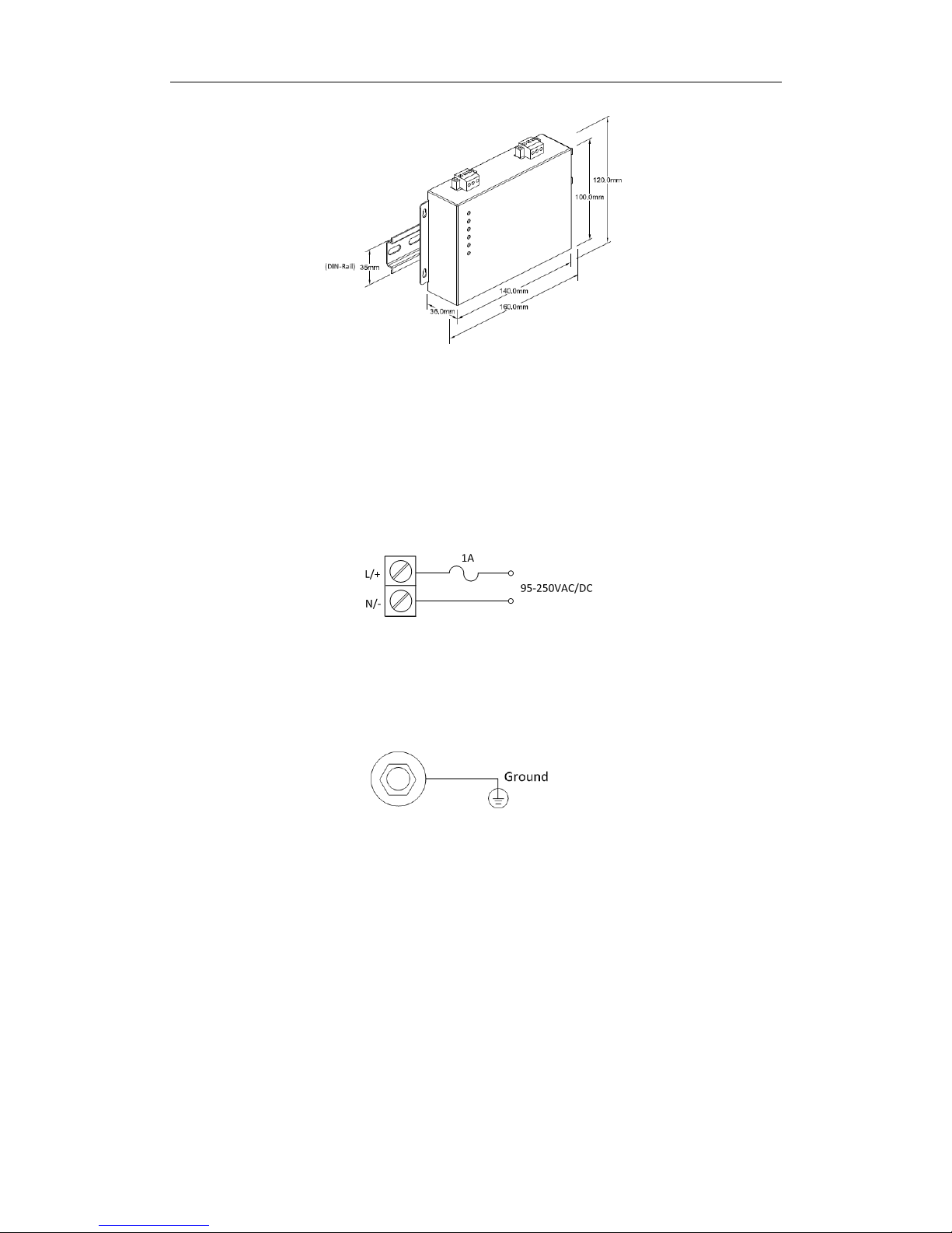
2.2 Unit Dimensions....................................................................................................................... 6
2.3 Mounting ................................................................................................................................... 6
2.4 Power Supply Wiring..............................................................................................................8
2.5 Chassis Ground Wiring........................................................................................................... 8
Chapter 3 Application........................................................................................................................ 9
3.1 LED Indicators ........................................................................................................................... 9
3.2 Typical Application .................................................................................................................. 9
Chapter 4 Communication Settings............................................................................................. 10
4.1 Baud Rate Settings (J1 and J2) ........................................................................................... 10
4.2 Communication Format Settings (J3) ..............................................................................11
4.3 Termination Resistor Settings (J4 to J8) .......................................................................... 11
Appendix A Technical Specifications ........................................................................................... 11
Appendix B Standards of Compliance......................................................................................... 13
Appendix C Ordering Guide ........................................................................................................... 14
Contact us ........................................................................................................................................... 14

Ceiec Electric Technology
5
Chapter 1 Introduction
This manual explains how to use the PMC-1220E RS485 hub. This chapter provides an overview of
the PMC-1220E and summarizes many of its key features.
1.1 Overview
The PMC-1220E is an Industrial RS485 hub with one upstream port and four downstream ports. Not
only can the PMC-1220E be used to increase the number of RS458 nodes beyond the 32 limit, it can
also be used to simplify the wiring for a RS-485 network by splitting a long segment into four
individual shorter segments, thus reducing labor and material costs while expanding the coverage area.
Each RS485 port is optically isolated to protect the connected devices from electrical surges as a result
of lightning or other electrical faults.
1.2 Features
One upstream RS485 port and four downstream RS485 ports
15kV ESD protection
3kV isolation protection on all RS485 signals
Dip-switch selectable baud rates from 1,200 to 38,400bps
< 1µs transmission delay between upstream and downstream ports
Built-in termination resistor for each port
Short circuit protection on the RS485 bus
Metal enclosure
DIN-Rail and Wall Mounting
Extended operating temperature
1.3 Typical Applications
Energy Management System, Building, Factory and Substation Automation
Simplify RS485 wiring and support segmentation
Increase the number of RS485 nodes from the standard 31 nodes to a maximum of 4x31 nodes
Contact CET Technical Support should you require further assistance with your application.
1.4 Getting more information
Additional information is available from CET via the following sources:
Visit www.ceiec-electric.com
Contact your local representative
Contact CET directly via email or telephone

Ceiec Electric Technology
6
Chapter 2 Installation
2.1 Appearance
Figure 2-1 Appearance
2.2 Unit Dimensions
Figure 2-2 Dimensions
2.3 Mounting
The PMC-1220E should be installed in a dry environment with no dust and kept away from heat,
radiation and electrical noise source. Installation steps:
Wall Mounting

Ceiec Electric Technology
7
Pre-drill the mounting holes based on the mounting diagrams below
Mount the device by affixing the supplied screws to the wall through the circular part of the key
holes on the mounting flange and then sliding the device downwards into position
Figure 2-3-1 Wall Mounting
DIN-Rail Mounting
Before installation, make sure that the 35mm DIN-Rail is already in place
Align the top of the mounting clip at the back of the PMC-1220E at an angle against the top of the
DIN rail as shown in the figure below
Rotate the bottom of the PMC-1220E towards the back while applying a slight downward pressure
at the top to make sure that the device is completely and securely fixed on to the DIN rail

Ceiec Electric Technology
8
Figure 2-3-2 DIN-Rail Mounting
2.4 Power Supply Wiring
The PMC-1220E comes standard with a 95-250VAC/DC universal power supply.
For AC supply, connect the live wire to the L/+ terminal and the neutral wire to the N/- terminal.
For DC supply, connect the positive wire to the L/+ terminal and the negative wire to the N/- terminal.
Figure 2-4 Power Supply Connections
2.5 Chassis Ground Wiring
The following figure illustrates the Chassis Ground connection.
Figure 2-5 Chassis Ground Connection

Ceiec Electric Technology
9
Chapter 3 Application
3.1 LED Indicators
PMC-1220E’s front panel is equipped with six LED indicators –P0, P1, P2, P3, P4 and PWR. When
power is applied, the PWR indicator will lit up. When the serial ports (P0, P1, P2, P3 and P4) are
connected and have activities, the Px (P0, P1, P2, P3, P4) indicator will blink.
LED
Color
Function
PWR
Red
Supply power indicator
P0
Green
Upstream RS485 activities on Port 0
P1
Green
Downstream RS485 activities on Port 1
P2
Green
Downstream RS485 activities on Port 2
P3
Green
Downstream RS485 activities on Port 3
P4
Green
Downstream RS485 activities on Port 4
Table 3-1 LED Indicators
3.2 Typical Application
The following figure illustrates the typical application of the PMC-1220E:
Figure 3-1 Typical Application

Ceiec Electric Technology
10
Chapter 4 Communication Settings
The communication settings for the PMC-1220E are controlled by Jumpers on its PCB. To configure
the PMC-1220E, the metal enclosure must first be removed to reveal the Jumpers' locations.
Jumpers J1 to J8 are located on the PMC-1220E’s PCB as illustrated in Figure 4-1 below.
Figure 4-1 Jumper Locations
Jumper
Description
J1
Baud Rate Settings for downstream RS485 ports P1 to P4
J2
Baud Rate Settings for upstream RS485 port P0
J3
Communication Format Settings
J4
Termination Resistor Settings for P1
J5
Termination Resistor Settings for P2
J6
Termination Resistor Settings for P3
J7
Termination Resistor Settings for P4
J8
Termination Resistor Settings for P0
Table 4-1 Jumper Descriptions
4.1 Baud Rate Settings (J1 and J2)
The baud rate settings are described in Table 4-2.The default settings is 9600 for all RS485 ports.
J1 and J2 (Baud Rate Settings)
Baud Rate
pin1
pin2
pin3
pin4
pin5
1200
Not Installed
Not Installed
Not Installed
Not Installed
Not Installed

Ceiec Electric Technology
11
2400
Not Installed
Not Installed
Not Installed
Not Installed
Installed
4800
Not Installed
Not Installed
Not Installed
Installed
Installed
9600*
Not Installed
Not Installed
Installed
Installed
Installed
19200
Not Installed
Not Installed
Installed
Installed
Installed
38400
Installed
Installed
Installed
Installed
Installed
* Default setting
Table 4-2 Baud Rate’s setting
4.2 Communication Format Settings (J3)
The communication format settings are described in Table 4-3.The default setting is 11 Bits for all
RS485 ports.
J3
Communication Formats
Not Installed*
11 Bits (1 Start Bit + 8 Data Bit + 1 Parity Bit +1 Stop Bit)
11 Bits (1 Start Bit + 8 Data Bit + No Parity Bit + 2 Stop Bits)
Installed
10 Bits (1 Start Bit + 8 Data Bit + No Parity Bit + 1 Stop Bit)
* Default setting
Table 4-3 Communication Format Settings
4.3 Termination Resistor Settings (J4 to J8)
In certain situation, a termination resistor may be required to prevent signal reflection that would
cause serial data corruption. The PMC-1220E comes equipped with a built-in 120 Ωtermination
resistor for each RS485 port that can be enabled by changing the jumper settings on the PCB board.
The termination resistor settings are described in Table 4-4. The default setting for the termination
resistor is Disabled for all RS485 ports.
Jumper
Termination Resistor Settings
Not Installed
Installed
J4
Built-in 120 Ω termination resistor between D+ and D- for P1
Disabled*
Enabled
J5
Built-in 120 Ω termination resistor between D+ and D- for P2
Disabled*
Enabled
J6
Built-in 120 Ω termination resistor between D+ and D- for P3
Disabled*
Enabled
J7
Built-in 120 Ω termination resistor between D+ and D- for P4
Disabled*
Enabled
J8
Built-in 120 Ω termination resistor between D+ and D- for P0
Disabled*
Enabled
* Default setting
Table 4-4 Termination Resistor Settings

Ceiec Electric Technology
12
Appendix A Technical Specifications
Serial Ports (P0, P1, P2, P3, P4)
Standard
Baud rate
RS485 Port
1200 to 38,400bps
LED Indicators
Power (Red)
Supply power indicator
P0 (Green)
Upstream RS485 activities on Port 0
P1 (Green)
Downstream RS485 activities on Port 1
P2 (Green)
Downstream RS485 activities on Port 2
P3 (Green)
Downstream RS485 activities on Port 3
P4 (Green)
Downstream RS485 activities on Port 4
Power Supply (L/+, N/-)
Standard
Burden
95-250VAC/DC, 47-440Hz
<3W
Protection
ESD Protection
15kV for all signals
Isolation Protection
3kV for all signals
Environmental Conditions
Operating Temp.
Storage Temp.
Humidity
Atmospheric pressure
-25°C to +70°C
-40°C to +85°C
5% to 95% non-condensing
70 kPa to 108kPa
Mechanical Characteristics
Casing
Unit Dimensions
Shipping Weight
Shipping Dimensions
Mounting
IP Rating
Galvanized Iron
36x120x140mm
0.752kg
70x185x145mm
DIN-Rail and Wall Mounting
30

Ceiec Electric Technology
13
Appendix B Standards of Compliance
Safety Requirements
Insulation
Dielectric Test
Insulation Resistance
Impulse Voltage
IEC 60255-5-2000
2kV @ 1 minute
>100MΩ
5kV
Electromagnetic Compatibility
Electrostatic Discharge
IEC 61000-4-2:2008 Level III
Radiated Fields
IEC 61000-4-3:2008 Level III
Fast Transients
IEC 61000-4-4:2004 Level III
Surges
IEC 61000-4-5:2005 Level III
Conducted Disturbances
IEC 61000-4-6:2008 Level IV
Magnetic Fields
IEC 61000-4-8:2009 Level IV
Oscillatory Waves
IEC61000-4-12:2006 Level III
Mechanical Tests
Vibration Test
Response
IEC 255-21-1:1988 Level I
Endurance
IEC 255-21-1:1988 Level I
Shock Test
Response
IEC 255-21-2:1988 Level I
Endurance
IEC 255-21-2:1988 Level I
Bump Test
IEC 255-21-2:1988 Level I

Ceiec Electric Technology
14
Appendix C Ordering Guide
Contact us
Ceiec Electric Technology Inc. Headquarters
8/F, Westside, Building 201, Terra Industrial & Tradepark, Che Gong Miao, Shenzhen, Guangdong, P. R.
China 518040
Tel: +86.755.8341.5187
Fax: +86.755.8341.0291
Email: support.international@ceiec-electric.com
Web: www.ceiec-electric.com
Table of contents
Popular Switch manuals by other brands

Moxa Technologies
Moxa Technologies EDS-505A Series Hardware installation guide

CHINT
CHINT YBLX-WL Mounting instructions

Waters Network Systems
Waters Network Systems GSM2109 operating manual

NETGEAR
NETGEAR ProSAFE GS108PEv3 installation guide

Marley
Marley 440 Series user manual

ANTAIRA
ANTAIRA LNX-1604G-SFP Series user manual