CEL-MAR ADA-4040 User manual

User manual
ADA-4040
Separator-repeater RS-485 / RS-422
1
io_ada-4040_v3.30_en
ADA-4040
Copyright © 2001-2020 CEL-MAR sp.j.

Contents
1. ENERAL INFORMATION.....................................................................................................................................................................3
1.1. WARRANTED INFORMATION...................................................................................................................................................... 3
1.2. ENERAL CONDITIONS FOR SAFE USE...................................................................................................................................3
1.3. CE LABEL...................................................................................................................................................................................... 3
1.4. ENVIRONMENTAL PRESERVATION...........................................................................................................................................3
1.5. SERVICE AND MAINTENANCE.................................................................................................................................................... 3
1.6. PACK CONTENTS......................................................................................................................................................................... 3
2. PRODUCT INFORMATION.................................................................................................................................................................... 3
2.1. PROPERTIES................................................................................................................................................................................ 3
2.2. DESCRIPTION............................................................................................................................................................................... 4
2.3. ISOLATION.................................................................................................................................................................................... 4
3. INSTALLATION...................................................................................................................................................................................... 5
3.1. ASSEMBLIN ................................................................................................................................................................................ 5
3.2. CONNECTION TO RS485/RS422 NETWORK..............................................................................................................................5
3.2.1. EXTENSION AND SEPARATION OF RS-485 / RS-422 BUS..............................................................................................5
3.2.1.1. SEPARATION OF RS485 INTERFACE OF DEVICE FROM THE RS485 4-WIRE BUS.............................................5
3.2.1.2. SEPARATION OF RS485 (2-WIRE) INTERFACE OF DEVICE FROM THE RS485 (4-WIRE) BUS..........................5
3.2.1.3. SEPARATION OF RS485 (4-WIRE)/ RS422 INTERFACE OF DEVICE FROM THE RS485 (2-WIRE) BUS.............6
3.2.1.4. SEPARATION OF RS485 (2-WIRE) INTERFACE OF DEVICE FROM THE RS485 (2-WIRE) BUS..........................6
3.2.1.5. RS422 INTERFACE DEVICE CONNECTION TO RS485(2W) BUS............................................................................6
3.2.1.6. EXTENSION AND SEPARATION OF RS485(4W) BUS SE MENTS.........................................................................7
3.2.1.7. EXTENSION AND SEPARATION OF RS485(2W) BUS SE MENTS.........................................................................8
Fig 9. Extension about 1200m and separation of RS485(2W) bus segments...........................................................................8
3.2.1.8. EXTENSION AND SEPARATION OF RS485(2W) & RS485(4W) BUS SE MENTS..................................................9
3.2.2. ND TERMINAL CONNECTION........................................................................................................................................10
3.2.3. LINE TERMINATION........................................................................................................................................................... 10
3.3. POWER SUPPLY........................................................................................................................................................................ 10
4. CONFI URATION................................................................................................................................................................................ 10
4.1. OPERATIN MODE SETTIN .................................................................................................................................................... 10
4.2. FACTORY DEFAULT................................................................................................................................................................... 10
5. ACTIVATION........................................................................................................................................................................................ 10
5.1. SI NALLIN LEDS..................................................................................................................................................................... 10
5.2. TROUBLESHOOTIN ................................................................................................................................................................. 10
6. VERSIONS........................................................................................................................................................................................... 11
7. SPECIFICATION.................................................................................................................................................................................. 11
2
ADA-4040

1. GENERAL NFORMAT ON
Thank you for your purchase of CEL-MAR Company product. This product has been completely tested and is covered by a two year
warranty on parts and operation from date of sale.
If any questions or problems arise during installation or use of this product, please do not hesitate to contact Technical Support at +48
41 362-12-46 or e-mail support@cel-mar.pl.
1.1. WARRANTED NFORMAT ON
The ADA-4040 separator-repeater is covered by a two year warranty from date of sale. The warranty does not cover damage caused
from improper use, materials consumption or any unauthorized changes. If the product does not function (is damaged), or not operate
in accordance with the instructions will be repaired.
All warranty and no warranty repairs must be returned with paid transport and insuring to the CEL-MAR Company.
CEL-MAR Company under no circumstances won't be responsible for ensuing damage from improper using the product or as a result
of random causes: the lightning discharge, the flood, the fire and the like.
CEL-MAR Company is not be held responsible for damages and loss including: loss of profits, loss of data, pecuniary losses ensuing
from using or the impossibility of using this product.
In specific cases CEL-MAR Company discontinue all warranties and in particular do not follow the user manual and do not accept
terms of warranty by the user.
1.2. GENERAL COND T ONS FOR SAFE USE
The device should be installed in a safe and stable places (eg, electroinstallation cabinet), the powering cable should be arranged so
as not to be exposed to trampling, attaching, or pulling out of the circuit.
Do not put device on the wet surface.
Do not connect devices for nondescript powering sources,
Do not damage or crush powering wires.
Do not make connection with wet hands.
Do not adapt, open or make holes in casings of the device!
Do not immerse device in water or no other liquid.
Do not put the fire opened on device sources: candles, an oil lamps and the like.
Complete disable from the supply network is only after disconnecting the power supply circuit voltage.
Do not carry out the assembly or dis-assembly of the device if it is enabled. This may result to short circuit and damage the device.
The device can not be used for applications that determine human life and health (eg. Medical).
1.3. CE LABEL
The CE symbol on the device CEL-MAR means compatibility with electromagnetic compatibility Electromagnetic
Compatibility Directive EMC 2014/30/WE.
Declaration of Conformity is delivered with purchased device.
1.4. ENV RONMENTAL PRESERVAT ON
This sign on the device inform about putting expended device with other waste materials. Device should send to the
recycling. (In accordance with the act about the Electronic Appliance Expended from day 29 of July 2005)
1.5. SERV CE AND MA NTENANCE
ADA-4040 separator-repeater does not require the servicing and maintenance.
Technical support is available at number +48 41 362-12-46 in 8.00-16.00, from Monday to Friday or e-mail support@cel-mar.pl.
1.6. PACK CONTENTS
ADA-4040 separator-repeater; user manual; CE declaration; resistors: Rt 120W (ohms), 5%, 0,25W(4pcs.).
2. PRODUCT NFORMAT ON
2.1. PROPERT ES
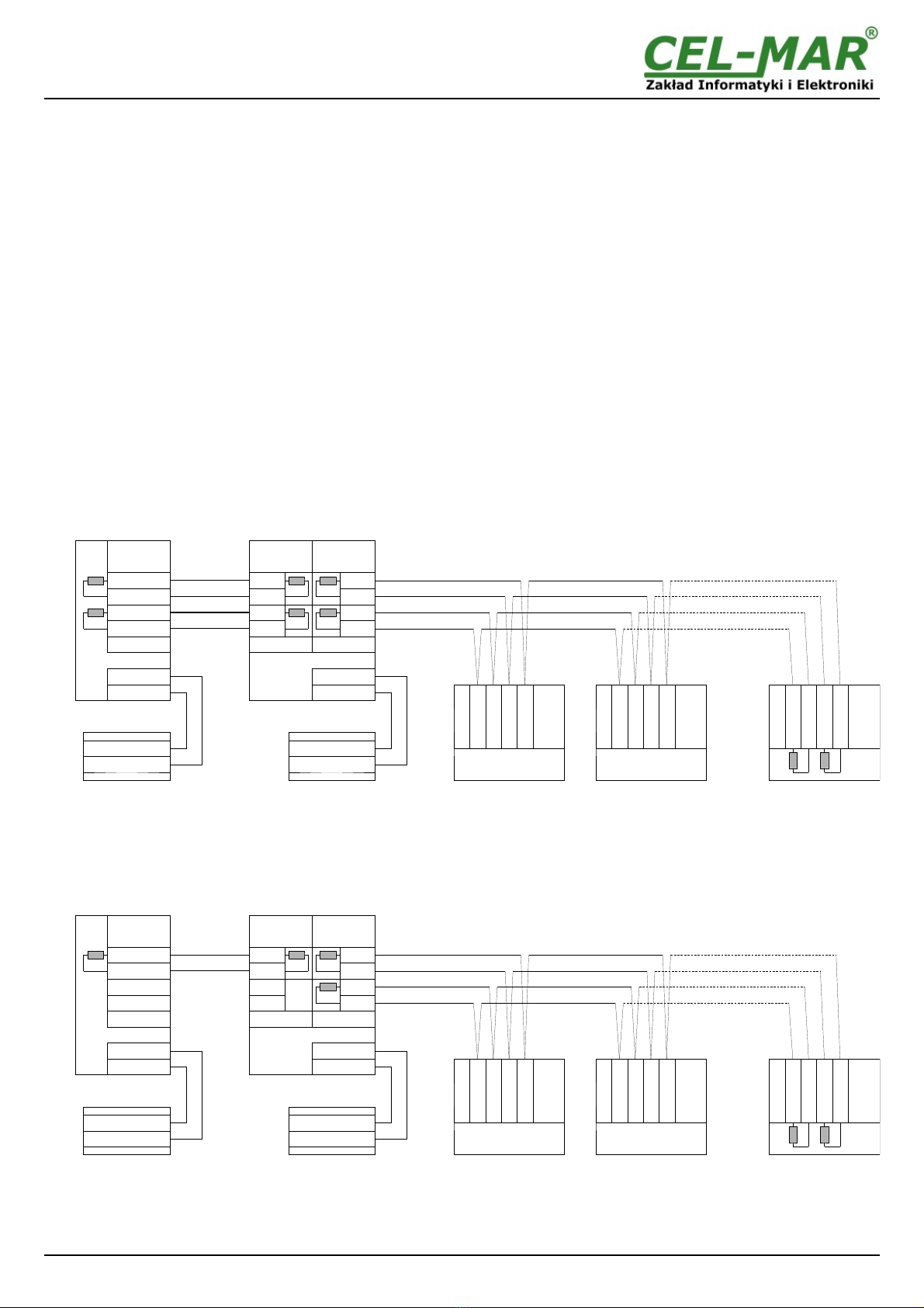
●Operating on 2-wire or 4-wire bus in RS485/RS422 standard,
●Baud rate up to 230,4 kbps,
●Transparent for all protocols: MODBUS, DNP, PROFIBUS and other,
●Any a data format, specified EIA-485, CCITT V.24 specifications,
●Power supply 10 - 30 VDC stable,
● ~3kV= optoisolation in signal channel between RS485/RS422 (RS1) and RS485/RS422 (RS2)
●1kV= or 3kV= galvanic isolation between RS485/RS422 (RS1, RS2) interface and power supply,
●Connection RS485/RS422 networks and power supply via screw terminal block,
●Implemented short circuit protection and over-voltage protection on RS485 / RS422 lines,
●Protection against power supply reverse connection,
●Implemented protection reverse polarity power supply,
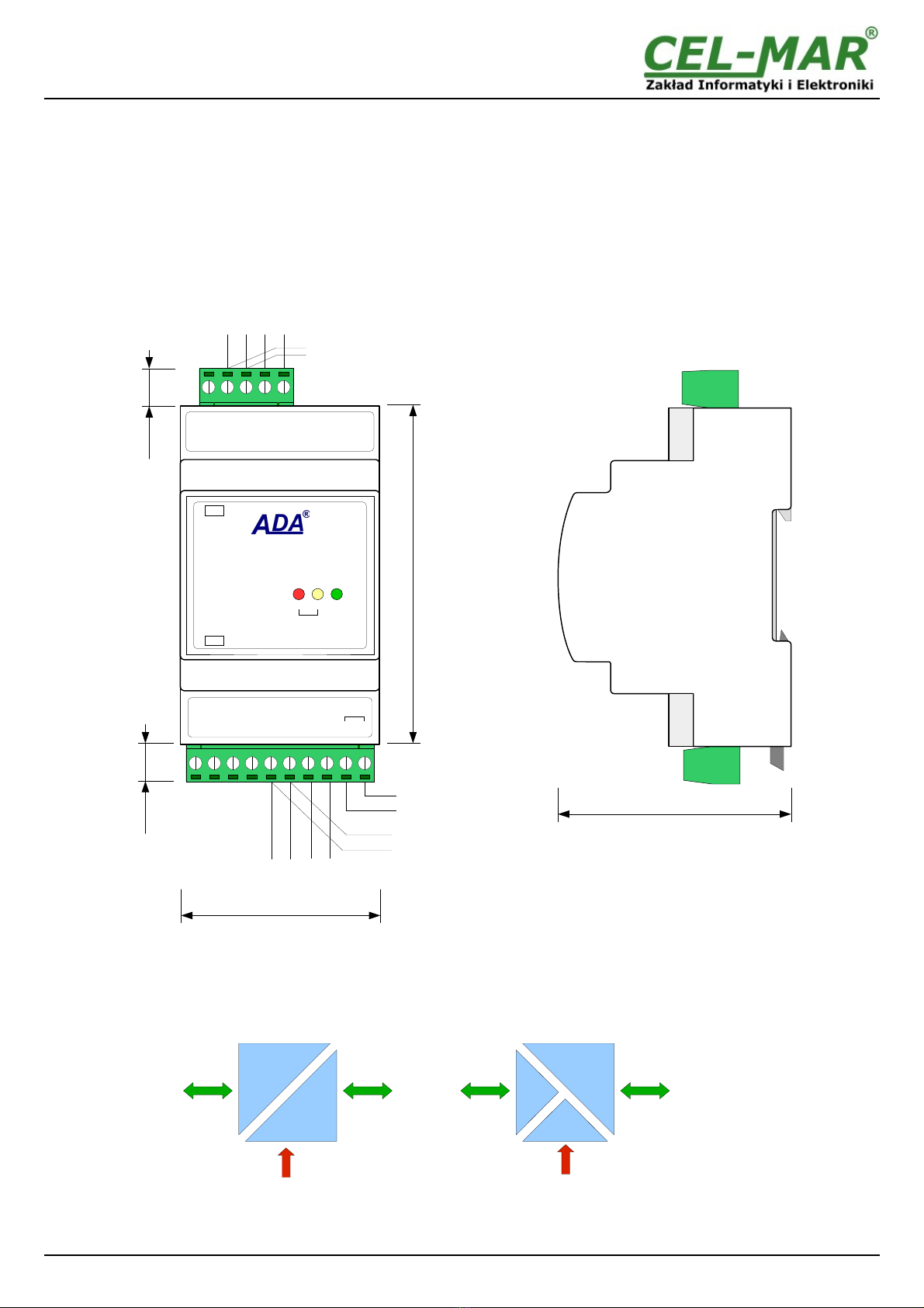
●DIN 43880 standard - mounting in typical electro-installation unit,
●Rail mounting according to DIN35 / TS35 standard,
●Dimensions (W x D x H) 53mm x 62mm x 90mm.
3
ADA-4040

2.2. DESCR PT ON
ADA-4040 separator-repeater is a device used for separation and extension of RS485/422 bus, about next segment 1200m (without
interference with data format). The distance is being reduced in case of large baud rate (over 115,2 Kb). The separator-repeater can
be used for communication with other, remote devices with RS485/422 interface eg controllers or scales; using the lines
RX+,RX-,TX+/A,TX-/B.
The ADA-4040 transmits data at baud rate up to 230,4 kbps, through four or two twisted-pair connected to a terminal block. To
RS485/422 bus created by the use ADA-4040, it is possible to connect 32 devices, operating in half duplex or full duplex mode. The
1kVDC or 3kVDC galvanic isolation and ~3kVDC optoisolation in signals line separate RS1/OUT (RS485/RS422) interface from
RS2/IN (RS485/RS422) interface. Protect a device connected to RS2/IN from overvoltage, which appear on RS485/422 bus,
connected to RS1/OUT and in the power-circuit.
Over-voltage protection on each RS485/422 lines, was made on the base overvoltage LED's and the fuses. The ADA-4040 should be
powered from the power supply stabilized voltage with a voltage in the range 10 - 30 VDC and minimum power 2W.
Fig 1. View and location of SW1 micro-switch (under the cover)
2.3. SOLAT ON
The separator-repeater ADA-4040 has (depend on version) 2-way or 3-way and 1kV= or 3kV= galvanic isolation. The descriptions are
in section VERSIONS.
Fig 2. solation diagram
4
ADA-4040
POWER SUPPLY
10 - 30VDC
POWER SUPPLY
10 - 30VDC
RS1
RS485/RS422
RS2
RS485/RS422
3-WAY GALVAN C SOLAT ON2-WAY GALVAN C SOLAT ON
RS1
RS485/RS422
RS2
RS485/RS422
62mm
Power Supply
10 - 30 VDC
90mm
53mm
10mm 10mm
(SW1)
GND
TX+ /A
TX- /B
RX+
RX-
(RS485/RS422)
RS-485 4-wires
or RS-422
RS-485
2-wires
NC
NC
NC
GND
TX+ /A
TX- /B
RX +
RX -
(RS485/RS422)
V -
V +
10 – 30
VDC
PWRTXRX
ADA-4040
REPEATER RS-485/RS-422
RS485-RS1
RS1
RS2
RS-485
2-wires
RS-485 4-wires
or RS-422

3. NSTALLAT ON
This chapter will show how to connect ADA-4040 to RS485/422 bus and power supply and how to use it..
To reduce disturbance from environment, it is recommended to:
–use multi-pair type shielded cables, which shield can be connected to the earthing on one end of the cable,
–use the suitable diameter cable for power supply on account of voltage drop,
–use the powering cable with a suitable section because of the voltage drops,
–use the interference eliminators for powering the converter,
–lay signal cables at a distance of not less than 25 cm away from power cables,
–not powering the converters form the power-circuit of devices generate large impulse disturbance like contactors, relays, inverters.
3.1. ASSEMBL NG
The ADA-4040 case is adapted to assembly on TS-35 (DIN35) rail. To install converter should mount device on the rail upper part of
the case then press bottom part to hearing characteristic „Click” sound.
3.2. CONNECT ON TO RS485/RS422 NETWORK
RS485/RS422 interface at ADA-4040 separator-repeater is available on terminal block described as: Tx+/A, Tx-/B, Rx+, Rx- ND.
ADA-4040 support operating on RS422 bus and RS485 (2-wire and 4-wire). Both buses need proper cabling.
3.2.1. EXTENS ON AND SEPARAT ON OF RS-485 / RS-422 BUS
Using the ADA-4040 it is possible to extend the RS485/422 bus of next segment 1200m and make the galvanic separation of next
segments of the bus. It increases the reliability of the system operation based on RS485/422 bus.
Example connections of the ADA-4040 are shown below.
3.2.1.1. SEPARAT ON OF RS485 NTERFACE OF DEV CE FROM THE RS485 4-W RE BUS
Fig 3. Separation of RS485(4W)/422 port of device from RS485 4-W RE bus
3.2.1.2. SEPARAT ON OF RS485 (2-W RE) NTERFACE OF DEV CE FROM THE RS485
(4-W RE) BUS
Fig 4. Separation of RS485(2W) port of device from RS485 4 W RE bus
5
ADA-4040
Devices with RS485(4W) interface
RS485(4W)
connector
Tx-
ND
Rx+
Rx-
Tx+
Tx-
ND
Rx+
Rx-
Tx+
Tx-
ND
Rx+
Rx-
Rt
Tx+
Rt
Rt
Rt
Rx+
Rx-
ND
Tx+ / A
Tx- / B
Vss+
Vss-
V-
V+
ADA-4040
RS1
RS485 (4W)
RS2
RS485 (4W)
power supply
RS485(4W)
connector
Tx+
Tx-
ND
Rx+
Rx-
Device with RS485(4W)
interface
Rt
Rt
Rx+
Rx-
-
Tx+ / A
Tx- / B
Rt
Rt
Vss+
Vss-
V -
V +
power supply
RS485(4W)
connector
RS485(4W)
connector
Devices with RS485(4W) interface
RS485(4W)
connector
Tx-
ND
Rx+
Rx-
Tx+
Tx-
ND
Rx+
Rx-
Tx+
Tx-
ND
Rx+
Rx-
Tx+
Rt
Rt
Rt
Rx+
Rx-
ND
Tx+ / A
Tx- / B
Vss+
Vss-
V-
V+
ADA-4040
RS1
RS485 (2W)
RS2
RS485 (4W)
power supply
RS485 (2W)
connector
-
-
ND
A
B
Device with RS485 (2W)
interface
Rt
Rx+
Rx-
-
Tx+ / A
Tx- / B
Rt
Rt
Vss+
Vss-
V -
V +
power supply
RS485(4W)
connector
RS485(4W)
connector

3.2.1.3. SEPARAT ON OF RS485 (4-W RE)/ RS422 NTERFACE OF DEV CE FROM THE RS485
(2-W RE) BUS
Fig 5. Separation of RS485(4W)/422 port of device from RS485 2-W RE bus
3.2.1.4. SEPARAT ON OF RS485 (2-W RE) NTERFACE OF DEV CE FROM THE RS485
(2-W RE) BUS
Fig 6. Separation of RS485(2W) port of device from RS485(2W) 2-W RE bus
3.2.1.5. RS422 NTERFACE DEV CE CONNECT ON TO RS485(2W) BUS
Fig 7. Connection of device with RS422 to RS485(2W) 2-W RE bus
6
ADA-4040
Devices with RS485 (2W) interface
RS485 (2W)
connector
NC
ND
A
B
NC
Rt
Rt
Rx+
Rx-
ND
Tx+ / A
Tx- / B
Vss+
Vss-
V-
V+
ADA-4040
RS1
RS485 (2W)
RS2
RS485 (2W)
power supply
RS485 (2W)
connector
-
-
ND
A
B
Device with RS485 (2W)
interface
Rt
Rx+
Rx-
-
Tx+ / A
Tx- / B
Rt
Vss+
Vss-
V -
V +
power supply
RS485 (2W)
connector
RS485 (2W)
connector
NC
ND
A
B
NC
NC
ND
A
B
NC
Devices with RS485 (2W) interface
RS485 (2W)
connector
NC
ND
A
B
Rt
NC
Rt
Rt
Rx+
Rx-
ND
Tx+ / A
Tx- / B
Vss+
Vss-
V-
V+
ADA-4040
RS1
RS485 (4W)
RS2
RS485 (2W)
power supply
RS422
connector
Tx+
Tx-
ND
Rx+
Rx-
Device with RS422
interface
Rt
Rt
Rx+
Rx-
-
Tx+ / A
Tx- / B
Rt
Vss+
Vss-
V -
V +
power supply
RS485 (2W)
connector
RS485 (2W)
connector
NC
ND
A
B
NC
NC
ND
A
B
NC
Devices with RS485 (2W) interface
RS485 (2W)
connector
NC
ND
A
B
Rt
NC
Rt
Rt
Rx+
Rx-
ND
Tx+ / A
Tx- / B
Vss+
Vss-
V-
V+
ADA-4040
RS1
RS485 (4W)
RS2
RS485 (2W)
power supply
RS485 (4W)
connector
Tx+
Tx-
ND
Rx+
Rx-
Device with RS485 (4W)
interface
Rt
Rt
Rx+
Rx-
-
Tx+ / A
Tx- / B
Rt
Vss+
Vss-
V -
V +
power supply
RS485 (2W)
connector
RS485 (2W)
connector
NC
ND
A
B
NC
NC
ND
A
B
NC

3.2.1.6. EXTENS ON AND SEPARAT ON OF RS485(4W) BUS SEGMENTS
Fig 8. Extension about 1200m and separation of RS485(4W) bus segments
7
ADA-4040
Devices with RS485(4W) interface
RS485 (4W)
connector
RS1
RS485 (2W)
RS2
RS485 (4W)
power supply
RS485 (4W)
connector
RS485 (4W)
connector
Tx+
Tx-
ND
Rx+
Rx-
Rt
Rt
Rt
Rt
Rx+
Rx-
ND
Tx+ / A
Tx- / B
Vss+
Vss-
V -
V +
ADA-4040
Rx+
Rx-
-
Tx+ / A
Tx- / B
Rt
Rt
Tx+
Tx-
ND
Rx+
Rx- Rt
Rt
Tx-
ND
Rx+
Rx-
Tx+
Devices with RS485(4W) interface
RS485 (4W)
connector
Tx-
ND
Rx+
Rx-
Tx+
RS485 (4W)
connector
Tx-
ND
Rx+
Rx-
Tx+
RS485 (4W)
connector
Tx-
ND
Rx+
Rx-
Tx+

3.2.1.7. EXTENS ON AND SEPARAT ON OF RS485(2W) BUS SEGMENTS
Fig 9. Extension about 1200m and separation of RS485(2W) bus segments
8
ADA-4040
NC
NC
ND
A
B
Rt
Rt
Rx+
Rx-
ND
Tx+ / A
Tx- / B
Vss+
Vss-
V -
V +
ADA-4040
RS1
RS485 (2W)
RS2
RS485 (2W)
Rx+
Rx-
-
Tx+ / A
Tx- / B
Rt
NC
NC
ND
A
BRt
NC
ND
A
B
NC
NC
ND
A
B
NC
NC
ND
A
B
NC
NC
ND
A
B
NC
Devices with RS485 (2W) interface
RS485 (2W)
connector
power supply
RS485 (2W)
connector
RS485 (2W)
connector
RS485 (2W)
connector
RS485 (2W)
connector
RS485 (2W)
connector
Devices with RS485 (2W) interface

3.2.1.8. EXTENS ON AND SEPARAT ON OF RS485(2W) & RS485(4W) BUS SEGMENTS
Fig 10. Extension and separation of RS485(4W) 4-W RE and RS485(2W) 2-W RE bus segments
9
ADA-4040
NC
NC
ND
A
B
Rt
Rt
Rt
Rt
Rx+
Rx-
ND
Tx+ / A
Tx- / B
Vss+
Vss-
V -
V +
ADA-4040
RS1
RS485 (4W)
RS2
RS485 (2W)
Rx+
Rx-
-
Tx+ / A
Tx- / B
Rt
NC
NC
ND
A
BRt
Tx-
ND
Rx+
Rx-
Tx+
NC
ND
A
B
NC
Tx-
ND
Rx+
Rx-
Tx+
Tx-
ND
Rx+
Rx-
Tx+
Devices with RS485 (2-W RE) interface
power supply
RS485 (2W)
connector
RS485 (2W)
connector
RS485 (2W)
connector
Devices with RS485 (4-W RE) interface
RS485 (4W)
connector
RS485 (4W)
connector
RS485 (4W)
connector

3.2.2. GND TERM NAL CONNECT ON
Connection of ND terminals of RS485/422 interfaces, devices connected to RS485/422 bus, should be done in the case of a
potential difference of the signals grounds on interfaces RS485 / RS422, which prevents proper data transmission.
Cannot connect to the GND terminal - cables screens, PE circuit of electrical installation, signals grounds of other devices.
3.2.3. L NE TERM NAT ON
The application of Line Termination (terminator) Rt = 120 W (ohms) will reduce electrical reflection in data line at high baud rate. It is
not needed below 9600Bd. The Line Termination resistor should be used if the distance is over 1000m @ 9600Bd or 700m @
19200Bd transmission, the resistor can be necessary if there are problems with the transmission correctness. The
terminators/resistors are connected to the terminal block of ADA-4040 on the RS485/RS422 interface. Example connection of Rt are
shown on Fig. 3, 4, 5, 6, 7, 8, 9.
3.3. POWER SUPPLY
The power supply to ADA-4040 should be DC (regulated) from the scope 10 V= to 30V= and nominal power 2W. The power cable
from DC power supplies to the device must not be longer than 3m. Observe the polarity, connect positive (+) of DC power supplies to
V+ and negative (-) end to V- terminal. ADA-4040 has the protection from opposite connection power supply.
If after power, on the front panel is not lit green LED PWR, check the power connection (polarity).
4. CONF GURAT ON
For configuration of ADA-4040 operating mode use a six-position dip switch SW1.
The SW1 is located next to RS485 terminal block (Fig.1) under the cover. For setting, remove the cover and use small, flat
screwdriver.
4.1. OPERAT NG MODE SETT NG
The setting of SW1 dipswitch for operating mode of ADA-1040 is shown in the Table 1 (below).
In case of any questions, contact the support: support@cel-mar.pl.
Table 1
SW1-1 SW1-2 SW1-3 SW1-4 SW1-5 SW1-6 Description Operation mode
OFF OFF OFF OFF OFF OFF RS-422 Bus RS422 bus 4-wire.
Transmission full duplex or half duplex
ON ON ON ON ON ON RS485 Bus automatic data flow
control
RS485 bus 2-wire and 4-wire.
Transmission full duplex or half duplex.
4.2. FACTORY DEFAULT
During production ADA-4040 separator-repeater is configured to operating in RS485 mode as in table below.
Table 2
SW1-1 SW1-2 SW1-3 SW1-4 SW1-5 SW1-6
ON ON ON ON ON ON
5. ACT VAT ON
Converter can be powered after proper connection according to steps above.
If connection was made properly green LED PWR on front panel of converter should light, if not check polarization of power
connection. When data is present the LEDs Tx and Rx should blinking.
5.1. S GNALL NG LEDS
LED Description
PWR Signalling of Power Supply
RX Signalling of data receiving through RS1 port
TX Signalling of data transmitting through RS1 port
ATTENT ON!
AT BAUD RATE ABOVE 38.4 KBPS THE LED'S TX, RX W LL L GHT WEAKLY DUR NG DATA TRANSM SS ON
5.2. TROUBLESHOOT NG
Problem Solutions
PWR LED is not lights. Check polarization and parameters of connected power supply.
Rx LED lights continuously RS485(4W) /RS422 bus. Wrong polarization on Rx+, Rx- terminals. Change polarization.
RS485(2W) bus. Wrong polarization on Tx+/A, Tx-/B terminals. Change polarization.
No transmission,
Tx LED is blinking
RS485(4W) /RS422 bus. Check the correctness of connection to Tx, Rx terminals according
to chapter 2.
RS485(2W) bus. Check the correctness of configuration setting according to chapter 3.
10
ADA-4040

6. VERS ONS
ADA-4040 - - -
Order example:
Product Symbol: ADA-4040-1-23-3
1 – basic electronics version,
2 – 1kV=,3-way galvanic isolation,
3 – cover without inlets, plug-in screw terminal block
Electronics version:
Basic 1
Special 2
Galvanic isolation:
1kV=, 2-way 2
1kV=, 3-way 23
3kV=, 2-way 3
3kV=, 3-way 33
Terminal & Terminal Cover:
Cover without inlets, screw terminal block 1
Cover with inlets, screw terminal block 2
Cover without inlets, plug-in screw terminal block 3
7. SPEC F CAT ON
TECHN CAL DATA
Transition Parameters
nterface RS1 RS-485/422 RS2 RS-485/422
Connector Screw terminal block - max. Ø 2,5mm2
Line length 1200 m
Maximum number of connected device 32
Transmission line 1-pair or 2-pair twisted cable, UTP Nx2x0,5 (24AW ), shield in environment of large
interference STP Nx2x0,5 (24AW )
Standards EIA-485, CCITT V.11
Maximum baud rate 230,4 kbps
Transmission type Asynchronous full duplex, half duplex.
Optical signalisation
•PWD – green LED power supply,
•RX - red LED data receiving on RS1 – RS485/RS422,
•TX - yellow LED data transmission via RS1 – RS485/RS422.
Electrical Parameters
Power requirements 10 - 24 – 30 V DC
Power Cable Recommended length of power cable – up to 3m
Power 2W
Protection from reverse power polarization YES
Galvanic solation 1kV DC or 3kV DC - between power circuit and RS485/422 signal line
Optoisolation ~3kV - between signals lines RS-485/RS-422 (RS1) and RS-485/RS-422 (RS2)
Electromagnetic compatibility Resistance to disruptions according to the standard PN-EN 55024.
Emission of disruptions according to the standard PN-EN 55022.
Safety requiring According to the PN-EN60950 norm.
Environment Commercial and light industrial.
Environmental Parameters
Operating temperature -30 ÷ 60°C
Humidity 5 ÷ 95% - non-condensing
Storage temperature -40 ÷ 70 °C
Mounting Rail mounting according to DIN35 standard / TS35.
11
ADA-4040

Casing
Dimensions 53mm x 90mm x 62 mm
Material PC/ABS
Degree of casing protection IP40
Degree of terminal protection IP20
Weight 0,10 kg
According to standard DIN EN50022, DIN EN43880
Location during work Free
Mounting method On the rail compliant with DIN35 / TS35 standard.
12
ADA-4040
Dear Customer,
Thank you for purchasing CEL-MAR Company products.
We hope that this user manual helped connect and start up the ADA-4040 separator-repeater. We also wish to inform you that we
are a manufacturer of the widest selections of data communications products in the world such as: data transmission converters with
interface RS232, RS485, RS422, USB, Current Loop, Fibre-Optic Converters and Ethernet or Wi-Fi.
Please contact us to tell how you like our products and how we can satisfy you present and future expectation.
CEL-MAR sp.j.
Zakład Informatyki i Elektroniki
str. Ściegiennego 219C
25-116 Kielce, POLAND
Tel....................................................: +48 41 362-12-46
Tel/fax.............................................. : +48 41 361-07-70
Web................................................. : http://www.cel-mar.pl/en
Office............................................... : office@cel-mar.pl
Sales department........................... .: handlowy@cel-mar.pl
Technical information ..................... : support@cel-mar.pl
Table of contents
Other CEL-MAR Repeater manuals