
______________________________________________________________________________________
-5-
Field Installation Manual
Connection Type # 1
Use this instruction
If 20 Amp circuit breaker is available in customer Main Breaker Panel.
ES-1E is designed for use with Main Breaker Panel Single Phase 120/240V AC
up to 200 Ampere.
ES-1E unit should be mounted with four appropriate sized fasteners before connect to
Main Breaker Panel.
1.1 Power Connections
1.11 Remove the Panel cover of ES-1E exposing internal connections.
1.12 Locate Earth Terminal in ES-1E, connect the earth wire to ES-1E Earth Terminal. Connect the other
side of earth wire to main breaker panel ground rod. Ensure all mechanical connections are secure
and making full contact.
1.13 Locate existing 2 Pole 20 Amp Circuit Breaker in the Main Breaker Panel.
(a) Connect the wire L1 to Phase 1 of 20 Amp circuit breaker.
(b) Connect the wire L2 to Phase 2 of 20 Amp circuit breaker.
1.14 Qualified Representative must inspect size of cable 10 AWG.
1.15 Connect power cables to T1 Terminal Block of ES-1E.
1.2 Current Sensor Connections
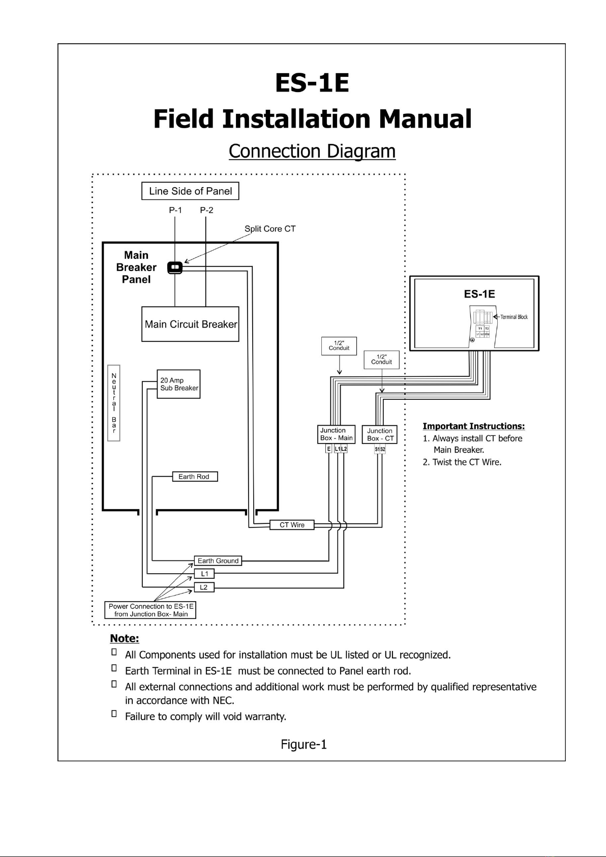
1.21 Open one side of split CT (Current Sensor). Clip the CT on the wire L1 before main Circuit Breaker
as shown in the (fig-1) Page-6.
1.22 Locate terminal block T2 (S1-S2) in ES-1E.
1.23 Qualified Representative line side of Main Panel should connect the wires from external CT to
T2 (S1-S2), preferably twisted.
1.24 Firmly secure current sensor to line side (L1) of main circuit breaker.


 user manual")


