Celera Motion MicroE Mercury II MII6500 User manual

©2018 Celera Motion 125 Middlesex Turnpike | Bedford, MA 01730-1409 USA
Sensor Installation Manu
Mercury II™6000
Series Encoders
Sensor Installation
Manual and
Reference Guide
>CELERAMOTION

Table of Contents
IM-1004 | REV181127 Page i ©2018 Celera Motion
Mercury II 6000 Series Encoders
Sensor Installation Manual and Reference Guide
Table of Contents
1.0Introduction ...................................................................................................................................... 1
1.1Overview ............................................................................................................................. 1
1.2Precautions ......................................................................................................................... 1
1.3Laser Safety Information.....................................................................................................1
1.4Standards Compliance........................................................................................................ 2
1.5Related Documentation ...................................................................................................... 2
1.6Manual Revisions................................................................................................................ 2
1.7Trademarks ......................................................................................................................... 2
2.0Before Installation ............................................................................................................................ 3
2.1Power Recommendations................................................................................................... 3
2.2Installation Considerations..................................................................................................3
2.3Items Required for Installation ............................................................................................ 3
3.0System Overview ............................................................................................................................. 4
3.1System View ....................................................................................................................... 4
3.2Expanded View ................................................................................................................... 4
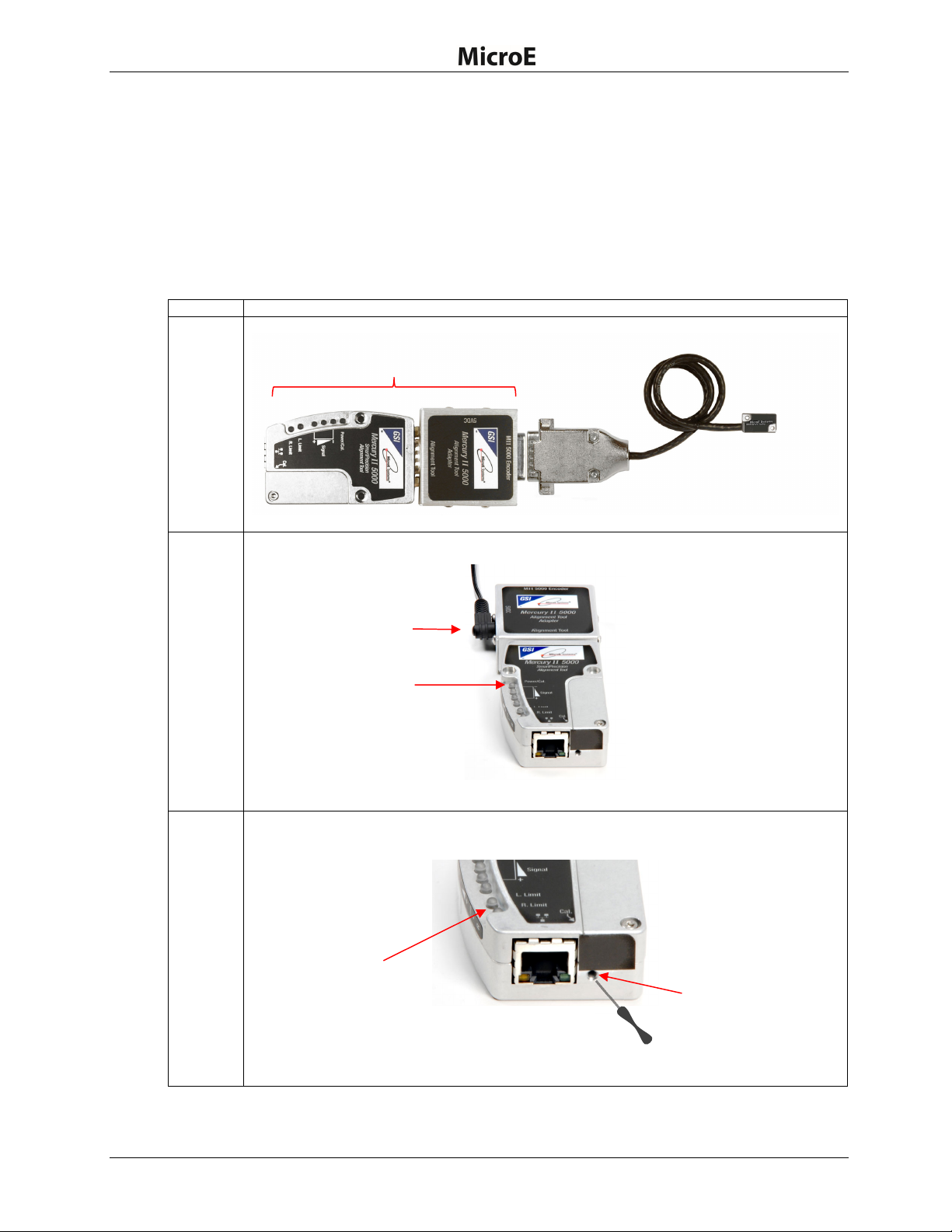
3.3SmartPrecision Alignment Tool........................................................................................... 5
4.0Sensor Installation............................................................................................................................ 6
4.1Sensor Mounting Orientation and Tolerances .................................................................... 6
4.2Verify Sensor Mounting Surface Height.............................................................................. 6
4.3Install Sensor ...................................................................................................................... 6
5.0Sensor Alignment and Calibration ................................................................................................... 7
5.1Using the Cal. Pushbutton .................................................................................................. 8
5.1.1Sensor Alignment................................................................................................... 8
5.1.2Sensor Calibration ............................................................................................... 10
5.2Using the Software............................................................................................................ 13
5.2.1Connect the Alignment Tool and Encoder ........................................................... 13
5.2.2Use the FindMII Program to Locate the Encoder ................................................ 14
5.2.3Sensor Alignment and Calibration ....................................................................... 15
6.0Alignment Verification with Connector LEDs ................................................................................. 18
7.0Appendix ........................................................................................................................................ 19
7.1Specifications .................................................................................................................... 19
7.2Resolution and Maximum Speed Tables .......................................................................... 21
7.3Wiring Diagrams................................................................................................................ 24
7.4Customer Interface............................................................................................................ 26
7.5Serial Interface Specifications........................................................................................... 29
7.6Index Speed Considerations............................................................................................. 35
7.7RS-422 Compliance .......................................................................................................... 36
7.8Troubleshooting ................................................................................................................ 37
8.0Order Guide ................................................................................................................................... 38
9.0Contacting Celera Motion............................................................................................................... 42

Introduction
IM-1004 | REV181127 Page 1 ©2018 Celera Motion
Mercury II 6000 Series Encoders
Sensor Installation Manual and Reference Guide
1.0 Introduction
1.1 Overview
The instructions in this manual apply to the following Mercury II 6000 Series Encoders:
MII6500 MII6700 MII6800
MII6800Si MII6800Pa
Refer to the Mercury II 6000 Series Encoder data sheet for additional details on ordering parts.
1.2 Precautions
1. Follow standard ESD precautions. Turn power to off before connecting
the sensor.
2. Do not touch electrical pins without static protection such as a grounded
wrist strap.
1.3 Laser Safety Information
This product is sold solely for use as a component (or replacement) in an electronic product;
therefore, it is not required to, and does not comply with U.S. FDA 21 CFR 1040.10 and 1040.11
which pertain to complete laser products. The manufacturer of the complete system-level
electronic product is responsible for complying with 21 CFR.
MicroE Systems encoders contain an infrared laser diode or diodes. Emitted invisible laser
radiation levels have been measured to be within the CDRH Class 1 range, which is not
considered hazardous; however, to minimize exposure to the diverging beam, install the encoder
sensor in its operational configuration in close proximity to the encoder scale before
applying power.
Invisible laser radiation; wavelength: 850 nm.
Maximum power of 4.8 mW CW for Mercury II.
Caution: The use of optical instruments with this product will increase eye hazard. Do
not view directly with optical instruments (microscopes, eye loupes, or magnifiers).
All maintenance procedures such as cleaning must be performed with the MicroE encoder
turned off.
Do not insert any reflective surface into the beam path when the encoder is powered.
Do not attempt to service the MicroE encoder.

Introduction
IM-1004 | REV181127 Page 2 ©2018 Celera Motion
Mercury II 6000 Series Encoders
Sensor Installation Manual and Reference Guide
1.4 Standards Compliance
Mercury II models are CE and RoHS compliant.
1.5 Related Documentation
Mercury II 6000 Series Encoders Data Sheet
Mercury II 6000 Series Encoders Interface Drawings
Mercury II PurePrecision Tape and Glass Scale Installation Manual
1.6 Manual Revisions
V
ersion Date Notes
Rev. 1 11/21/2014 Initial Release. Combines coverage for entire series of Mercury II 6000
Encoders.
Rev. 1A 11/30/2015 Correction on page 30: changed A6 to A
6
for CRC Bits section. Updated
document to Celera Motion standards. Updated Manual Revisions table.
180131 01/31/2018 Correction to ordering code.
181127 11/27/2018 Changed Section 4.2 scale to sensor Z-height tolerance.
1.7 Trademarks
Mercury II™, PurePrecision™, and SmartPrecision™ are trademarks of MicroE Systems®.
1.8 Special Conventions Used
The following symbols may be used in this document.
Symbol Description
Warning or caution: potential damage to parts.
Instructions show correct method.
Instructions show example of incorrect method.
See Section 2.2 Single click with the mouse on these highlighted references
to jump to specified places in instructions.

Before Installation
IM-1004 | REV181127 Page 3 ©2018 Celera Motion
Mercury II 6000 Series Encoders
Sensor Installation Manual and Reference Guide
2.0 Before Installation
Review the items in this section prior to installing the encoder.
2.1 Power Recommendations
Mercury II encoders require a minimum of 4.75 VDC continuously.
When designing circuits and extension cables to use Mercury II encoders, be sure to
account for voltage loss over distance and tolerances from the nominal supply voltage so
that at least 4.75 VDC is available to the Mercury II encoder under all operating conditions.
The input voltage should not exceed 5.25 VDC.
2.2 Installation Considerations
The Mercury II encoder is a precision electronic instrument. It has been designed to function in a
wide range of applications and environments. To take full advantage of the Mercury II modular
system design, considerations should be made to allow easy access to the sensor (and
interpolator modules where applicable) for service and/or replacement. For optimal performance
and reliability:
DO follow standard ESD precautions while handling the sensor and interpolator.
DO allow proper clearance for sensor head alignment.
DO follow setup and calibration instructions for the encoder system.
DO, where possible, install the scales in an inverted or vertical position to minimize
accumulation of dust.
DO NOT store sensors in an uncontrolled environment.
DO NOT electrically overstress the sensor (power supply ripple/noise).
DO NOT intentionally “hot swap” the sensor if the device is energized.
DO NOT use in high contamination applications (dust, oil, excessive humidity, or other
airborne contaminants).
2.3 Items Required for Installation
In addition to the items identified in Section 3.0 System Overview, you will need the following
items available for installation:
Items Required for Installation
Item Tape Scale Glass Scale
Index and Limit Marker sheets
Hex Wrench for Sensor Mounting Screws
Finger Cots or talc-free gloves
Acetone or isopropyl alcohol
Lint-free cotton cloths or wipes
Two-part epoxy (Tra-Bond 2116 or equivalent)
Stick and disposable surface for stirring epoxy
Shears
Tape Applicator Tool*
Silicone adhesive
Note*:Not required for some installations.

System Overview
IM-1004 | REV181127 Page 4 ©2018 Celera Motion
Mercury II 6000 Series Encoders
Sensor Installation Manual and Reference Guide
3.0 System Overview
This section identifies parts for the sensor installation.
3.1 System View
3.2 Expanded View
Index Marker15-Pin Male
D-Sub Connector
Double-Shielded
Cable
Left Limit Marker
Scale Mounting Surface Reference Edge (Benching Surface)
Tape Scale: shown mounted on
a fixed (non-moving) substrate.
Sensor: shown mounted on
a linear bearing using a
mounting bracket.
Alignment Tool
Sensor Connector
Mounting Screws
Typical User-Supplied
Sensor Mounting Bracket
Sensor Mounting Holes
Sensor Benching Pins
Bracket Mounting Holes
Right Limit Marker
Alignment Tool Adapter

System Overview
IM-1004 | REV181127 Page 5 ©2018 Celera Motion
Mercury II 6000 Series Encoders
Sensor Installation Manual and Reference Guide
3.3 SmartPrecision Alignment Tool
The Mercury II ATMII5000 SmartPrecision Alignment Tool is required for aligning the Mercury II
6000 Series Encoders. The Alignment Tool includes the following:
Alignment Tool
SmartPrecision
II Software
USB Cable
Power Supply
For more details, see Sensor Installation Tools in Section 8.0 Order Guide for more details.
Mercury II 5000 Alignment Tool LEDs
LED Function
Power/Cal. Indicates power is on and when in
alignment mode
Red Signal Strength Indicates improper alignment
Yellow Signal Strength Indicates improved alignment
Green Signal Strength Indicates proper alignment
Left Limit Blinks in Alignment Mode and when
sensor is located over left limit
Right Limit Blinks in Alignment Mode and when
sensor is located over right limit
Power/Cal. LED
15 Pin D-Sub
Sensor Connector
Left Limit LED
Cal. Pushbutton
Ethernet Connector
Alignment Tool
Ada
p
te
r
Red Signal Strength LED
Yellow Signal Strength LED
Green Signal Strength LED
Right Limit LED
Alignment Tool
Power Supply
Connect

Sensor Installation
IM-1004 | REV181127 Page 6 ©2018 Celera Motion
Mercury II 6000 Series Encoders
Sensor Installation Manual and Reference Guide
4.0 Sensor Installation
This section contains instructions for installing the sensor.
4.1 Sensor Mounting Orientation and Tolerances
Refer to the following specifications when installing and aligning the sensor.
Orientation
Tolerances
Mercury II 6000
Sensor Alignment Tolerances
Axis Alignment Tolerance
X Direction of Motion
Y ± 0.20 mm
Z ± 0.15 mm
X ± 1.0°
Y ± 1.0°
Z ± 2.0°
4.2 Verify Sensor Mounting Surface Height
Step Action
1. Verify that the vertical distance between the reference surface of the sensor and the top of the
scale is as follows:
Tape scale/marker tape after blue protective film is removed: 3.09 mm +/-0.15
Linear or rotary glass scales: 2.93 mm +/-0.15
2. Check the height at a location on the scale where there are no index or limit markers.
4.3 Install Sensor
Step Action
1. Install the sensor on the mounting surface referencing the appropriate datum surface as
shown in the MII6000 Interface Drawings. Use two M-2 screws to loosely attach the sensor.
Note: Do not tighten the two M2 screws at this time.
2. Use benching pins to locate the sensor if the system's mechanical tolerances are adequate.
Refer to the MII6000 Interface Drawings for recommended locations and heights of pins.
Sensor Axes

Sensor Alignment and Calibration
IM-1004 | REV181127 Page 7 ©2018 Celera Motion
Mercury II 6000 Series Encoders
Sensor Installation Manual and Reference Guide
5.0 Sensor Alignment and Calibration
After installing the MII6000 encoder, use the SmartPrecision Alignment Tool ATMII5000 to align
and calibrate the sensor using one of the following methods:
Calibration (Cal.) Pushbutton: if you don’t have access to a computer or are very
experienced at performing encoder alignment and calibration.
SmartPrecision II Software: if you have access to a computer and either are new at
performing encoder alignment and calibration or want to take advantage of the graphic
interface.
Select a method:
Method Description
1.
Use the Calibration (Cal.) Pushbutton:
Align and calibrate the sensor head using the Calibration (Cal.) pushbutton and the LED
indicators on the Alignment Tool.
Continue to Section 5.1 Using the Cal. Pushbutton.
2.
Use the SmartPrecision II Software*:
Align and calibrate the sensor head using the Alignment Tool and the SmartPrecision II
Software.
Continue to Section 5.2 Using the Software.
Note*: The SmartPrecision II Software is built in to the Alignment Tool ATMII5000 for setup
and diagnostics; only a web browser is needed (use of software is optional). See
Sensor Installation Tools in Section 8.0 Order Guide for more details.
Access to Cal.
Pushbutton
Alignment Tool
LED Indicators
SmartPrecision II Screen

Sensor Alignment and Calibration
IM-1004 | REV181127 Page 8 ©2018 Celera Motion
Mercury II 6000 Series Encoders
Sensor Installation Manual and Reference Guide
5.1 Using the Cal. Pushbutton
Use the following instructions to perform sensor alignment and calibration by using the Cal.
Pushbutton located on the ATMII5000 Alignment Tool.
5.1.1 Sensor Alignment
Note: Make sure that the 5 VDC power input is disconnected. Encoder should never be
connected to an already energized alignment tool since equipment can be damaged.
Step Action
1. Connect the MII6000 encoder to the SmartPrecision Alignment Tool.
2. Insert the 5 VDC power connector to the Alignment Tool Adapter and apply power.
Result: The Power/Cal. LED illuminates a steady green. The sensor is initialized after an
approximate 10 second delay.
3. Enter the Alignment Mode by gently pressing and releasing the Cal. pushbutton quickly (within
a second) using a small screwdriver or similar tool.
Result: The two Limit LEDs will begin to blink in unison (slowly). Automatic Gain Control
(AGC) is now inactive. The AGC adjusts gain to maintain a steady signal level.
Alignment Tool
5 VDC Power
Alignment Tool Adapter
Encoder
Sensor Connector
Alignment Tool
Power/Cal. LED
Access to Cal.
Pushbutton
Limit LEDs
(
two
)
Screwdrive
r

Sensor Alignment and Calibration
IM-1004 | REV181127 Page 9 ©2018 Celera Motion
Mercury II 6000 Series Encoders
Sensor Installation Manual and Reference Guide
Step Action
4. Align the sensor by slowly sliding the sensor on its mounting surface in the Y or Z direction
until the green Signal Strength LED is illuminated*.
Note*: Optimal alignment is indicated by Bright Green.
5. Once the sensor is aligned, tighten the two sensor mounting screws (0.37 Nm [3.3 inch-lbs.]
maximum torque).
6. Move the sensor over the index mark and confirm that the green Signal Strength LED blinks.
Result:
If the green Signal Strength LED blinks when the sensor passes over the index, then
proceed to the next step.
If the green Signal Strength LED does not blink when the sensor passes over the index,
then loosen the mounting screws and repeat the alignment procedure (go back to Step 3).
Note*: Optimal alignment is indicated by Bright Green and a blink over the index.
7. Move the sensor over the entire length of the scale.
Result:
If the green Signal Strength LED remains illuminated over the entire length of travel (the
yellow and red LED’s do not illuminate), then proceed to the next step.
Otherwise, clean the scale and try Step 3 again. If cleaning the scale is not successful,
loosen the sensor mounting screws and repeat the alignment procedure (go back to
Step 3).
8. Press and release the Cal. button quickly to exit Alignment Mode.
Result: The limit LED’s will stop blinking and AGC will reactivate.
Slowly slide sensor on its mounting
surface in the Y or Z direction
Green Signal Strength LED
(Proper Alignment)*

Sensor Alignment and Calibration
IM-1004 | REV181127 Page 10 ©2018 Celera Motion
Mercury II 6000 Series Encoders
Sensor Installation Manual and Reference Guide
5.1.2 Sensor Calibration
Perform calibration when installing the sensor for first time, or if the sensor is subsequently
remounted, or the scale is replaced. This section contains instructions for calibrating the following:
Linear Scales or Rotary Scales used in applications less than 360°
Rotary Scales used in applications greater than 360° without Limit Markers
Confirm Settings
Confirm the following before calibration:
Always perform calibration of the left and right limits while Limit Polarity is set to Limits
Normal mode. See the Left and Right Limits Settings in the Calibration and Align tab of
the SmartPrecision II Software in Section 5.2.3 Sensor Alignment and Calibration.
Select correct Reflective or Non-Reflective Grating Type on Status and Setup tab.
Note: Perform all procedures below at ≤1 meter/second relative motion between the sensor and
the scale.

Sensor Alignment and Calibration
IM-1004 | REV181127 Page 11 ©2018 Celera Motion
Mercury II 6000 Series Encoders
Sensor Installation Manual and Reference Guide
Linear Scales or Rotary Scales used in applications less than 360°
Step Action
1. To start calibration, press and hold the Cal. button for about two seconds until the Power/Cal.
LED starts blinking slowly.
2. Move the sensor 50 mm to perform Gain/Offset/Phase calibration. Move the sensor back and
forth if scale has <50 mm of measuring length.
Result: After calibration both limit LEDs come on steady.
3. Move the sensor to an area of the scale away from the index and limit markers. Press the Cal.
button once quickly.
Result: The Power/Cal. LED will start blinking quickly.
4.
Move the sensor over the index up to 20 passes (one pass is a single cycle back and forth).
Result: The Left Limit LED will start blinking quickly.
Note: If the sensor is positioned over the left limit marker, the Left Limit LED will come on
steady.
5. Move the sensor over the left limit marker and press the Cal. button once quickly.
Result: The Right Limit LED will start blinking.
Note: if the sensor is positioned over the right limit marker, the Right Limit LED will come on
steady.
6. Move the sensor over the right limit marker and press the Cal. button once quickly.
Result: All LEDs will flash together twice to indicate that setup is completed.
The encoder is now ready for connection to the controller for use in servo control.
7.
When calibration is complete, go to Section 6.0 Alignment Verification with Connector
LEDs to visually verify calibration using the LED indicators on the MII6000 sensor’s connector.
Note: To skip any portion of this calibration and move to the next procedure, press and hold the
Cal. button for two seconds.
Power/Cal. LED
Cal. Pushbutton
Limit Switches LEDs

Sensor Alignment and Calibration
IM-1004 | REV181127 Page 12 ©2018 Celera Motion
Mercury II 6000 Series Encoders
Sensor Installation Manual and Reference Guide
Rotary Scales used in applications greater than 360° without Limit Markers
Step Action
1.
To start calibration, press and hold the Cal. button for about 10 seconds: until the three Signal
LEDs blink twice to indicate that rotary calibration has been activated.
2.
Move the sensor 50 mm to perform Gain
/
Offset /Phase calibration. After calibration both limit
LED’s come on steady. Move the sensor back and forth if your scale has a circumference of
<50mm.
Result: After calibration both limit LEDs come on steady.
3.
Move the sensor to an area of the scale away from the index marker. Press the Cal. button
once quickly.
Result: The Power/Cal. LED will start blinking quickly.
4. Move the sensor over the index up to 20 passes (one pass is a single cycle back and forth).
Result: The Power/Cal. LED and both limit LEDs will start to blink in sets of three.
5.
Move the sensor away from the index and press the Cal. button once quickly.
Result: The Power/Cal. LED and both limit LED’s will start to blink in sets of two.
6. Move the sensor over the index once.
Result: The LEDs will change to Power/Cal. LED and both limit LEDs blinking just once.
7. Make a full revolution of the rotary scale in order to go over the index again in the same
direction. The two passes over the index must be at least 1000 20 µm fringes apart (equivalent
of 20 mm linear travel), if they are not, the Alignment Tool will wait for another pass that is 1000
fringes from the first.
Result: The encoder is now ready for connection to the controller for use in servo control.
8. When calibration is complete, go to Section 6.0 Alignment Verification with Connector
LEDs to visually verify calibration using the LED indicators on the MII6000 sensor’s connector.
Note: To skip any portion of` this calibration and move on to the next procedure, press and hold
the Cal. button for two seconds.
Signal LEDs (3)
Cal. Pushbutton
Power/Cal. LED

Sensor Alignment and Calibration
IM-1004 | REV181127 Page 13 ©2018 Celera Motion
Mercury II 6000 Series Encoders
Sensor Installation Manual and Reference Guide
5.2 Using the Software
Use the following instructions to perform sensor alignment and calibration using the Alignment
Tool and the SmartPrecision II Software.
5.2.1 Connect the Alignment Tool and Encoder
Step Action
1. Verify that the Alignment Tool Adapter/SmartPrecision II Alignment Tool is not powered on. The
Power/Cal. LED should be off.
2. Connect the MII6000 encoder and Ethernet cable as shown below.
3. Power up the Alignment Tool by plugging in 5 VDC to the Alignment Tool Adapter.
Result: The Power/Cal. LED illuminates a steady green. The sensor is initialized after an
approximate 10 second delay.
5 VDC Power Alignment Tool Adapter
Power/Cal. LED
Power/Cal. LED
Alignment Tool
Encoder
Ethernet Cable
Sensor Connector
Computer
(Windows or
other OS)

Sensor Alignment and Calibration
IM-1004 | REV181127 Page 14 ©2018 Celera Motion
Mercury II 6000 Series Encoders
Sensor Installation Manual and Reference Guide
5.2.2 Use the FindMII Program to Locate the Encoder
Step Action
1. Once the encoder is connected to the computer using an Ethernet cable, run the software
program FindMII (Mercury II Encoder Search Utility) version 1.2.2.1 or higher. To locate the
correct version for your operating system, go to Mercury II Software Downloads at
http://www.microesys.com/products/documentation or click on one of the following links:
For Windows operating systems: FindMII.exe
For all other operating systems: FindMII.jar
2.
The FindMII program locates the encoder and allows you to use the embedded SmartPrecision II
Software on your web browser.
Note: You may receive an Application Blocked by Security Settings message when
attempting to load the plotApplet. Go to the Java applet in your Control Panel and try reducing
the Security Level in the Security Tab.
Warning: Reducing the Security Level in the Security Tab may decrease protection of your
computer against malicious software.
3.
Once located, the FindMII program will list all the encoders connected to the network as seen in
the following example.
Encoder
found by the
program

Sensor Alignment and Calibration
IM-1004 | REV181127 Page 15 ©2018 Celera Motion
Mercury II 6000 Series Encoders
Sensor Installation Manual and Reference Guide
4. Double-click the name of the encoder to open the SmartPrecision II Software.
Results: The SmartPrecision II Software Screen opens.
5.2.3 Sensor Alignment and Calibration
Once the SmartPrecision II Software is open, perform sensor alignment and calibration by using
the Calibrate and Align tab.
Step Action
1.
Click on the Calibrate and Align tab.
Results: The Calibrate and Align screen opens.
Calibrate and Align Tab
Calibration Status
Calibration Type
Calibration Mode

Sensor Alignment and Calibration
IM-1004 | REV181127 Page 16 ©2018 Celera Motion
Mercury II 6000 Series Encoders
Sensor Installation Manual and Reference Guide
Step Action
2.
Turn on Align Mode by clicking on the Align Mode Turn On button.
Results: The Turn On button will change to Turn Off. Align Mode Status will change to On
(AGC Inactive). On the Alignment Tool, both Left and Right Limit LEDs will begin blinking.
3. Adjust the sensor position until the maximum signal strength is achieved. See the Signal Level
Indicator at the top of the SmartPrecision screen.
4. Tighten the sensor mounting screws. Check for index indication (using the status display at the
top right of the screen).
Results: The Index indication is “not at index” when the sensor is not located at the Index
marker, and “index crossed” when the sensor has passed over the Index marker.
5.
Turn off Align Mode by clicking on the Align Mode Turn Of
f
button.
Result: The Turn Off button will change to Turn On. Align Mode Status will change to Off
(AGC Active). On the Alignment Tool, both Left and Right Limit LEDs will stop blinking.
Signal Level Indicator
Align Mode Turn On/Off Button
Index Indication
Align Mode Turn On/Off Button
Limits Indication

Sensor Alignment and Calibration
IM-1004 | REV181127 Page 17 ©2018 Celera Motion
Mercury II 6000 Series Encoders
Sensor Installation Manual and Reference Guide
Step Action
6.
Perform setup by checking the Calibrate GOP, Calibrate Index, Set Left Limit, and Set Right
Limit boxes.
Note: Not all applications require all steps.
7.
Ensure that the Calibration Type is correctly selected for your encoder (linear/rotary secto
r
is
selected above). Press the Start button in Calibration Mode to begin calibration/setup.
Results: Sensor Calibration will begin. Follow the steps in the Calibration Status box to
complete setup of the MII6000 encoder. For example, in the status box above, the instructions
are to move the sensor until reaching 100% complete and then the next calibration step will
start.
8. If there is a failure, turn off the sensor and clean the scale. After cleaning, return to Section
5.2.3 Sensor Alignment and Calibration.
9. When calibration is complete, continue to the next section Alignment Verification with
Connector LEDs to visually verify calibration using the LED indicators on the MII6000 sensor’s
connector.
Start Button
Check Boxes

Alignment Verification with Connector LEDs
IM-1004 | REV181127 Page 18 ©2018 Celera Motion
Mercury II 6000 Series Encoders
Sensor Installation Manual and Reference Guide
6.0 Alignment Verification with Connector LEDs
Once the encoder is aligned and calibrated using the alignment tool, alignment can be visually
verified using the LED indicators on the MII6000 sensor’s connector.
Sensor Connector display (shown during normal operation):
Color Codes for Indicators
Mercury II Sensor Connectors
LED Indicators – Signal Strength
Colo
r
Signal Strength
Green Optimal
Yellow Marginal
Red Bad
Purple Saturated
Mercury II Sensor Connectors
LED Indicators – Limit/Index Markers
Colo
r
Limit/Index Mark
Green Over Index Mark
Blue Over Left Limit Mark
Red Over Right Limit Mark
None Not Over Any Mark
Signal Level LED indicates
signal strength of main track
(green is optimal)
Limit/Index LED Indicates presence of
left limit mark, right limit mark, or index
mark (no color indicates sensor not
positioned over any marks)
This manual suits for next models
5
Table of contents
Other Celera Motion Media Converter manuals