CELETTE RAPID SPOT MINI Operation instructions

ORIGINAL MANUAL
PRODUCT REF NO: CEL.11245-C-02
01/2023 - REV. 1.0
WWW.CELETTE.COM
RAPID SPOT MINI

www.celette.com Page No: 2
TABLE OF CONTENTS
FOREWORD........................................................................................................................................Page 3
1 SAFETY PRECAUTIONS.............................................................................................................Page 4
- 1.1 SYMBOL USAGE..............................................................................................................Page 4
- 1.2 OPERATION HAZARDS .................................................................................................Page 4
- 1.3 ADDITIONAL SYMBOLS FOR INSTALLATION, OPERATION, AND MAINTENANCE......Page 6
- 1.4 EMF INFORMATION.........................................................................................................Page 7
2 GENERAL TECHNICAL DESCRIPTIONS..................................................................................Page 7
3 MATTERS NEED ATTENTION..................................................................................................Page 8
- 3.1 SPOT WELDING...............................................................................................................Page 8
- 3.2 STUD WELDING MODE CABLE CONNECTION.........................................................Page 8
- 3.3 CONTROLS ON GENERATOR FRONT PANEL.........................................................Page 9
- 3.4 OPERATING PROCESS FOR STUD WELDING........................................................Page 9
- 3.4.1 PREPARATION FOR OPERATION.................................................................Page 9
4. TROUBLE SHOOTING ................................................................................................................Page 10
5. WIRE DRAWING ..........................................................................................................................Page 11
- 5.1 WIRE DRAWING FOR RAPID SPOT MINI 220V.....................................................Page 11
- 5.2 WIRE DRAWING FOR RAPID SPOT MINI 110V......................................................Page 12
6. RAPID SPOT MINI 1PH/220V EUROPE/INDIA...................................................................Page 13
7. RAPID SPOT MINI 1PH/110V USA........................................................................................Page 14

www.celette.com Page No: 3
FOREWORD:
IMPORTANT: Before starting the equipment, read the contents of this manual, which must be stored in a
place familiar to all users for the entire operative life-span of the machine. This equipment must be used
solely for welding operations.

www.celette.com Page No: 4
1. SAFETY PRECAUTIONS:
Protect yourself and others from injury - read, follow, and save these important safety precautions and
operating instructions.
DANGER! Indicates a hazardous situation which, if not avoided, will result in death or serious
injury. The possible hazards are shown in the adjoining symbols or explained in the text.
Indicates a hazardous situation which, if not avoided, could result in death or serious injury.
The possible hazards are shown in the adjoining symbols or explained in the text.
Notice: Indicates statements not related to personal injury.
Indicates special instructions.
1.1 SYMBOL USAGE:
This group of symbols mean WARNING! WATCH OUT! ELECTRIC SHOCK, MOVING PARTS, and HOT PARTS
hazard. Consult symbols and related instructions below for necessary actions to avoid the hazards.
1.2 OPERATION HAZARDS:
The symbolds shown below are used throughout this manual to call attention to and identify possible
hazards. When you see the symbol, watch out, and follow the related instructions to avoid the
hazard. The safety information to avoid the hazard. The safety information given below is only a
summary of the more complete safety information found in the safety standards listed in section
below. Read and follow all safety standards.
Only qualied persons should install, operate, maintain, and repair this equipment. A qualied person
is dened as one who, by possession of a recognized degree, certicate, or professional standing, or
who by extensive knowledge, training and experience, has successfully demonstrated ability to solve
or resolve problems relating to the subject matter, the work, or the project and has received safety
training to recognize and avoid the hazards involved.
During operation, keep everybody, especially children away.
SPOT WELDING CAN CAUSE FIRE OR EXPLOSION:
Sparks can fly off from the welding arc. The flying sparks, hot workpiece, and hot
equipment can cause res and burns. Accidental contact of electrode to metal
objects can cause sparks, explosion, overheating, or re. Check and be sure the
area is safe before doing any welding.
Remove all flammables within 35 ft (10.7 m) of the weld. If this is not possible, tightly cover them
with approved covers.
Do not spot weld where flying sparks can strike flammable material.
Protect yourself and others from flying sparks and hot metal.
Be alert that welding sparks can easily go through small cracks and openings to adjacent areas.
Watch for re, and keep a re extinguisher nearby.

www.celette.com Page No: 5
Do not weld on containers that have held combustibles, or on closed containers such as tanks, drums, or
pipes unless they are properly prepared according to AWS F4.1 and AWS A6.0 (see Safety Standards).
Do not weld where the atmosphere can contain flammable dust, gas, or liquid vapors (such as gasoline).
Remove any combustibles, such as a butane lighter or matches, from your person before doing any
welding.
After completion of work, inspect area to ensure it is free of sparks, glowing embers, and flames.
Do not exceed the equipment rated capacity.
Use only correct fuses or circuit breakers. Do not oversize or bypass them.
For hot work and have a re watcher and extinguisher nearby.
Wear body protection made from durable, flame-resistant material (leather, heavy cotton, wool).
Body protection includes oil-free clothing such as leather gloves, heavy shirt, cuffless trousers, high
shoes, and a cap.
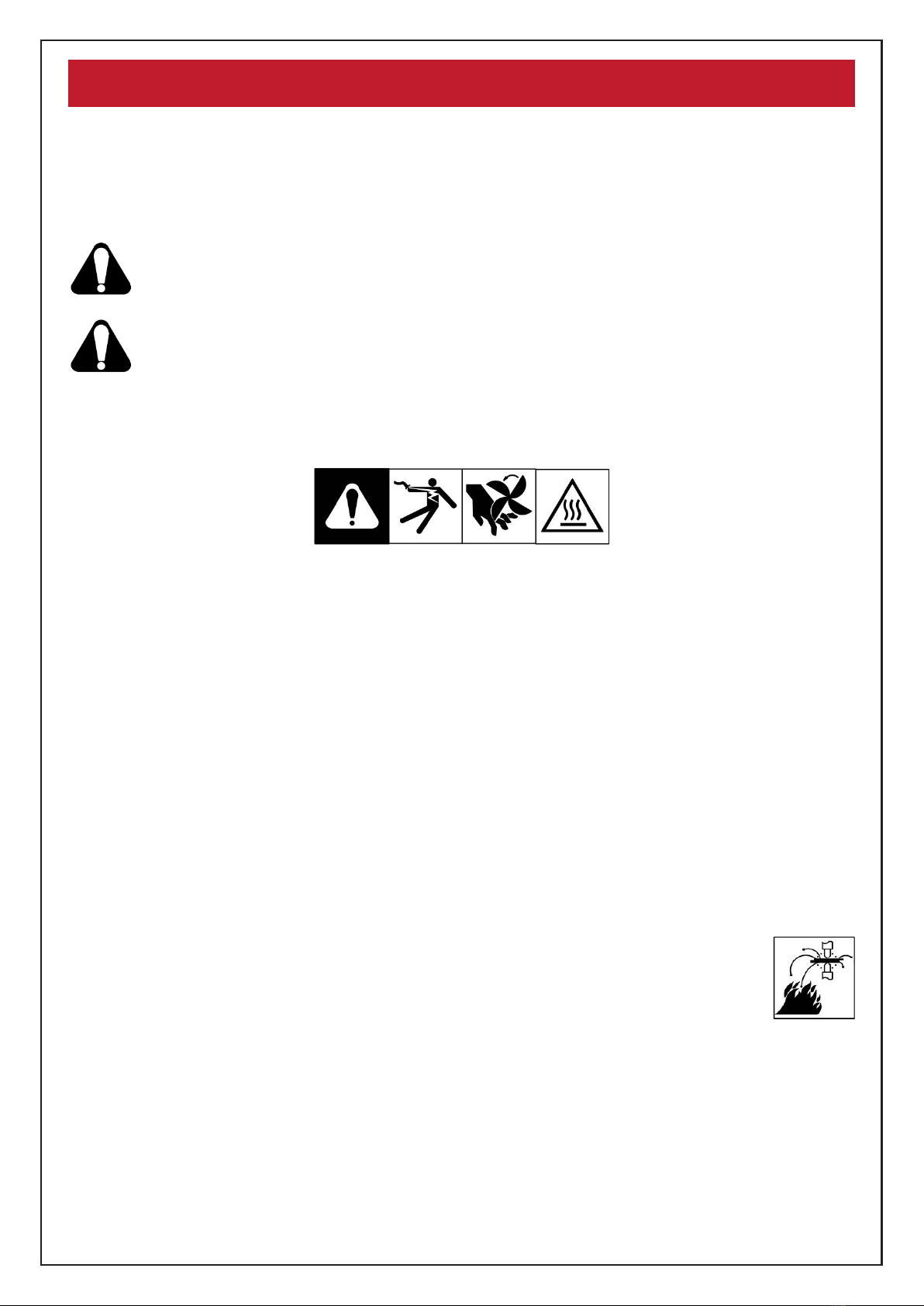
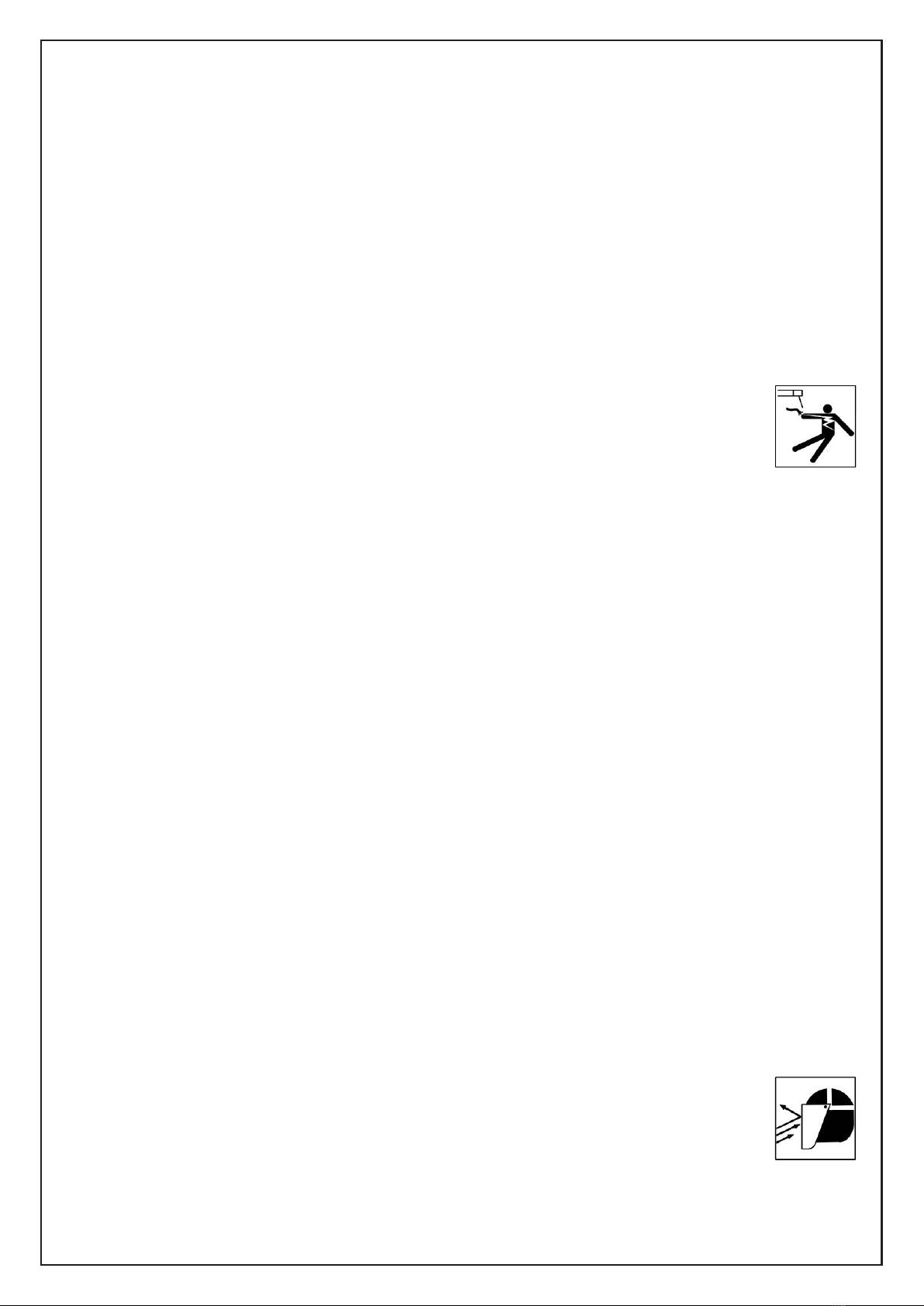
ELECTRIC SHOCK CAN KILL:
Touching live electrical parts can cause fatal shocks or severe burns. The input
power circuit and machine internal circuits are also live when power is on.
Incorrectly installed or improperly grounded equipment is a hazard.
Do not touch live electrical parts.
Wear dry, hole-free insulating gloves and body protection.
Additional safety precautions are required when any of the following electrically hazardous conditions
are present: in damp locations or while wearing wet clothing; on metal structures such as floors,
gratings, or scaffolds; when in cramped positions such as sitting, kneeling, or lying; or when there is a
high risk of unavoidable or accidental contact with the workpiece or ground. And, do not work alone!
Disconnect input power before installing or servicing this equipment.
Properly install, ground, and operate this equipment according to this manual and national, state, and
local codes.
Always verify the supply ground - check and be sure that input power cord ground wire is properly
connected to ground terminal in disconnect box or that cord plug is connected to a properly
grounded receptacle outlet.
When making input connections, attach the grounding conductor rst - double-check connections.
Keep cords dry, free of oil and grease, and protected from hot metal and sparks.
Frequently inspect input power cord and ground conductor for damage or bare wiring - replace
immediately if damaged - bare wiring can kill.
Turn off all equipment when not in use.
For water-cooled equipment, check and repair or replace any leaking hoses or ttings.
Do not use any electrical equipment if you are wet or in a wet area.
Use only well-maintained equipment. Repair or replace damaged parts at once.
Wear a safety harness if working above floor level.
Keep all panels, covers, and guards securely in place.
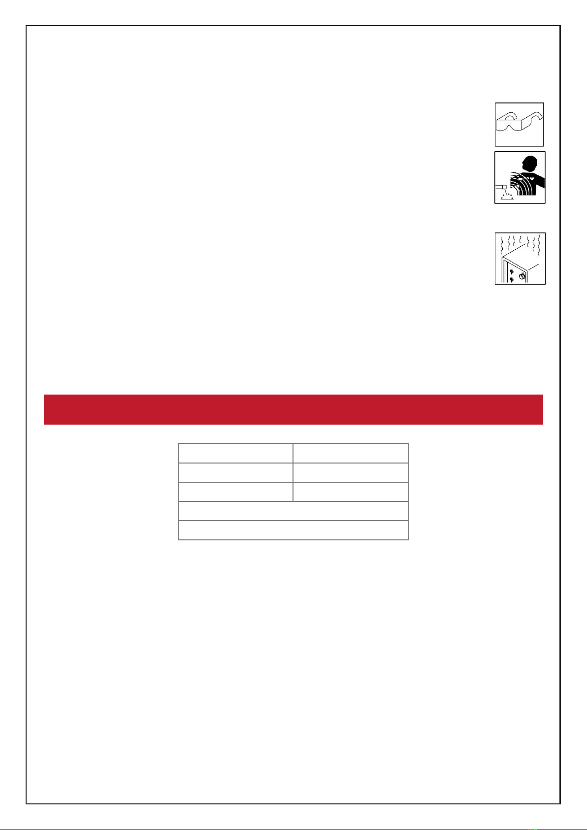
FLYING SPARKS CAN INJURE:
Very often sparks fly off from the joint area.
Wear approved face shield or safety goggles with side shields.
Wear body protection made from durable, flame-resistant material (leather, heavy cotton,
wool). Body protection includes oil-free clothing such as leather gloves, heavy shirt,
cuffless trousers, high shoes, and a cap.
Protect others in nearby areas by using approved flame-resistant or noncombustible re curtains or
shields. Have all nearby persons wear safety glasses with side shields.

www.celette.com Page No: 6
HOT PARTS CAN BURN:
Do not touch hot parts bare handed.
Allow cooling period before working on equipment.
To handle hot parts, use proper tools and/or wear heavy, insulated welding gloves
and clothing to prevent burns.
SIGNIFICANT DC VOLTAGE EXISTS AFTER REMOVAL OF INPUT POWER ON INVERTERS:
Turn Off inverter, disconnect input power, and discharge input capacitors according to instructions in
Maintenance Section before touching any parts.
FUMES AND GASES CAN BE HAZARDOUS:
Welding produces fumes and gases. Breathing these fumes and gases can be
hazardous to your health.
Keep your head out of the fumes. Do not breathe the fumes.
Ventilate the work area and/or use local forced ventilation at the arc to remove welding fumes and
gases. The recommended way to determine adequate ventilation is to sample for the composition
and quantity of fumes and gases to which personnel are exposed.
If ventilation is poor, wear an approved air-supplied respirator.
Read and understand the Safety Data Sheets (SDSs) and the manufacturer’s instructions for
adhesives, coatings, cleaners, consumables, coolants, degreasers, fluxes, and metals.
Work in a conned space only if it is well ventilated, or while wearing an air-supplied respirator.
Always have a trained watchperson nearby. Welding fumes and gases can displace air and lower the
oxygen level causing injury or death. Be sure the breathing air is safe.
Do not weld in locations near degreasing, cleaning, or spraying operations. The heat and rays of the
arc can react with vapors to form highly toxic and irritating gases.
Do not weld on coated metals, such as galvanized, lead, or cadmium plated steel, unless the
coating is removed from the weld area, the area is well ventilated, and while wearing an air-supplied
respirator. The coatings and any metals containing these elements can give off toxic fumes if welded.
1.3 ADDITIONAL SYMBOLS FOR INSTALLATION, OPERATION, AND MAINTENANCE:
FIRE OR EXPLOSION HAZARD:
Do not install or place unit on, over, or near combustible surfaces.
Do not install or operate unit near flammables.
Do not overload building wiring - be sure power supply system is properly sized,
rated, and protected to handle this unit.
FALLING EQUIPMENT CAN INJURY:
Use correct procedures and equipment of adequate capacity to lift and support
unit.
Follow the guidelines in the Applications Manual for the Revised NIOSH
Lifting Equation (Publication No. 94-110) when manually lifting heavy parts or
equipment.
Secure unit during transport so it cannot tip or fall.
READ INSTRUCTIONS:
Read and follow all labels and the Owner’s Manual carefully before installing,
operating, or servicing unit. Read the safety information at the beginning of the
manual and in each section.

www.celette.com Page No: 7
Use only genuine replacement parts from the manufacturer.
Perform installation, maintenance, and service according to the Owner’s Manuals, industry
standards, and national, state, and local codes.
FLYING METAL OR DIRT CAN INJURE EYES:
Wear approved safety glasses with side shields or wear face shield.
ELECTRIC AND MAGNETIC FIELDS (EMF) CAN AFFECT IMPLANTED MEDICAL DEVICES:
Wearers of Pacemakers and other Implanted Medical Devices should keep away.
Implanted Medical Device wearers should consult their doctor and the device
manufacturer before going near arc welding, spot welding, gouging, plasma arc cutting,
or induction heating operations.
OVERUSE CAN CAUSE OVERHEATING:
Allow cooling period; follow rated duty cycle.
Reduce duty cycle before starting to weld again.
1.4 EMF INFORMATION:
This machine is manufactured in compliance with the instructions contained in the harmonized standard,
and must be used solely for professional purposes in an industrial environment. There may be potential
difculties in ensuring electromagnetic compatibility in non-industrial environments. IN CASE OF
MALFUNCTIONS, REQUEST ASSISTANCE FROM QUALIFIED PERSONNEL.
2. GENERAL TECHNICAL DESCRIPTIONS:
MODEL: The model of the machine
SN Machine Serial Number which must appear on requests or inquiries
concerning the machine
CE, EN International standards
Model SN
CE ENXXXXXX
1~50/60Hz Input
Output max current
Duty cycle

www.celette.com Page No: 8
3. MATTERS NEED ATTENTION:
1. Input power is AC220≥15A.
2. Turn “off “ the switch, the machine is not use.
3. Make sure to turn “off” the switch while connecting (or) dis-connecting the cable to the AC supply.
4. The machine maintenance and repair must turn “off “ the switch after 5 minutes.
5. The stud clamp is inside the stud welding torch. The inside diameter of stud clamp must suitable the
stud screw. Do not use worn stud clamp.
6. Stud welding may cause welding arc and metal spatter, protect yourself with appropriate safety
garments and goggles.
7. Make sure there are no flammable materials near the work area.
3.1 SPOT WELDING:
3.2 STUD WELDING MODE CABLE CONNECTION:
NOTE:
1. The torch cable and earth use the euro-type quick connector. Please push the plug to the end of the
socket, torch cable to “Torch” socket, earth cable to “EARTH” socket, and turn right, they will connect well.
2. The input cable and control cable connectors have screw. Please lock the screw to xed the
connector.
3. The earth cable must use clamp to x on the base metal.
4. All cables must be kept straight. If the cables are winded, it will interfere with the stud welding.
FOR SPOT WELDING:
1. Washer contact
to work piece
2. Discrage-arc
SPOT WELDING TORCH
CONTROL CABLE
WORK PIECE
EARTH CABLES
3. Finish welding

www.celette.com Page No: 9
3.3 CONTROLS ON GENERATOR FRONT PANEL:
A. Output power adjustment for stud welding
B. Connection indicator
C. Socket for work clamp
D. Socket for torch
E. Control socket for torch
F. Power switch
G. Fuse
H. Input power cable (Conrm the power voltage before use)
3.4 OPERATING PROCESS FOR STUD WELDING:
NOTE: Protect your eyes and your body when stud welding. Please operate the machine as follow.
3.4.1 PREPARATION FOR OPERATION:
1. Keep the work piece free of dirt ,oil, paint and rust.
2. If the base metal is thin, it will dent at pressure. It must add a base plate, when stud welding.
3. Select suitable stud welding torch, according as material, diameter, length of the stud screw.
4. Make sure the diameter of the clamp is correct and the length of the gag lever post is correct.
Install the screw clamp and gag lever post in the torch.
5. Make sure all the cables connect to the machine and workpiece. Connect input cable and turn on.
C
E
A B D F G
H

www.celette.com Page No: 10
4. TROUBLE SHOOTING:
No power
1. Check the source power
2. Check the input cable
3. Check the main switch
4. Please contact to the manufacturer
No weld
1. Check the output cable for torch & earth
2. Check the connection for torch & earth
3. Check power fuse
4. Check transformer, maybe over heat
5. Please contact to the manufacturer
Fan is not working
1. Check the power of fan
2. Check the fan, maybe something stuck in the fan
3. Please contact to the manufacturer

www.celette.com Page No: 11
5. WIRE DRAWING:
5.1 WIRE DRAWING FOR RAPID SPOT MINI 220V:

www.celette.com Page No: 12
5.2 WIRE DRAWING FOR RAPID SPOT MINI 110V:

www.celette.com Page No: 13
6. RAPID SPOT MINI 1PH/220V EUROPE/INDIA:
No. Code Description No. Code Description
1 EY11245-CQ0101B1 Front panel 12 PD072402 Power board
2 EY11245-CH0101B1 Back panel 13 VC100630 Power transformer
3 EY11245-CS0101R16 Top cover 14 PD072501 Main control board
4 EY11245-CX0101B1 Bottom panel 15 SE064000 Cable holder
5 EY11245-CZ0101+ Inside baffle 16 XE071000-2E Power cord
6 MF094310 Fan net 17 KE055005 Main switch
7 SE063905 Cable holder 18 DG063002-E Fuse holder
8 SE055110 Knob DG084020 Fuse 10A
RA061000 Potentiometer 19 SC091120 Handle
9 DL092301 Green lamp 20 SG081100 Foot pad
10 MF094400 Fan 21 JD055043 Earth clamp
11 VM096200 Main transformer 22 QM081016 Euro type torch

www.celette.com Page No: 14
7. RAPID SPOT MINI 1PH/110V USA:
No. Code Description No. Code Description
1 EY11245-CQ0101B1 Front panel 12 PD072402 Power board
2 EY11245-CH0101B1 Back panel 13 VC100630 Power transformer
3 EY11245-CS0101R16 Top cover 14 PD072501 Main control board
4 EY11245-CX0101B1 Bottom panel 15 SE064000 Cable holder
5 EY11245-CZ0101+ Inside baffle 16 XJ082030-2C Power cord UL
6 MF094310 Fan net 17 KE055005 Main switch
7 SE063905 Cable holder 18 DG063002-E Fuse holder
8 SE055110 Knob DG084020 Fuse 10A
RA061000 Potentiometer 19 SC091120 Handle
9 DL092301 Green lamp 20 SG081100 Foot pad
10 MF094400 Fan 21 JD055043 Earth clamp
11 VM096200 Main transformer 22 QM081016 Euro type torch

THANK YOU!!!
FOR PURCHASING OUR PRODUCT
CELETTE FRANCE SAS
3, Avenue Marcellin Berthelot 38200 Vienne – France
+33 474 575 959
info@celette.com
www.celette.com
This manual suits for next models
1
Table of contents
Other CELETTE Welding System manuals
Popular Welding System manuals by other brands

Lincoln Electric
Lincoln Electric ASPECT 300 Operator's manual

Amada
Amada MH-1H-01 Operation manual

GYS
GYS NEOMIG-i 400 G manual

ESAB
ESAB HandyPlasma 550 Installation, operation and service manual

Saf-Fro
Saf-Fro PRESTO 300MV Instructions for use safety and maintenance

Kemppi
Kemppi Feed 400 operating instructions

Miller
Miller HF-251D-1 Specifications

EWM
EWM Tetrix 152 RC Plasma CW GR operating instructions

EWM
EWM SATURN MIG 200 operating manual

Lincoln Electric
Lincoln Electric POWERTEC 205C Series Operator's manual

Lincoln Electric
Lincoln Electric RANGER 250 IM919 Operator's manual

Miller
Miller XMT 300 CC/TIG owner's manual