Celexon PL1000 Plus User manual

celexon.
TM
www.celexon.com
EC declaration of conformity
Manufacturer: celexon Germany GmbH & Co. KG
Address: Gutenbergstraße 2, 48282 Emsdetten, DE
Hereby declares that the following product
Product name: celexon projector lift PL1000 Plus
Part number: PL1000 Plus
Manufacturer: celexon Germany GmbH & Co. KG,
48282 Emsdetten, DE
Complies with the following standards:
CE EN 50081-1, CE EN 50082-1
Notes:
The tests were carried out in normal mode and refer to the tested
device under the specied tests. This certicate applies only to the
devices tested.
Emsdetten, 10.07.2017
Christoph Hertz
Managing Director

celexon.
TM
Installation Manual
celexon projector lift PL1000 Plus
Thank you for purchasing this product. Before installing the projector lift,
please read the following instructions carefully.

1
Safety instructions
Disclaimer
Cleaning instructions
Do not start installation before reading the complete installation manual and the
safety warnings.
This product should only be installed by qualied personnel (with mechanical and
electrical experience).
Please ensure that the ceiling can carry the complete weight of ceiling lift and
mounted hardware.
If necessary, carry out the installation with another person to ensure safe
installation.
Tighten the screws but ensure that they are not overtightened as this would reduce
the load bearing capacity.
This product is designed for indoor use only. Outdoor use could result in damage
to the product and may cause injury.
Hanging loads must be tested at least twice a year for strength and carrying
capacity.
Do not stand under the ceiling lift during operation.
Do not dismantle the lift into its piece parts.
Do not lean heavy loads against the projector or lift.
The information in this document is subject to change without prior notice.
Changes will be documented in future editions of this manual. The manufacturer
does not guarantee accuracy of the information contained in this document.
Clean the product only with a soft and clean cloth. If necessary, use a mild soapy
solution to remove any dirt.

2
Symbols
Product label
This ceiling lift is clearly identied by a product identication label that contains its
key technical information.
A Product type
B Product name
C Serial number
D Year of manufacture
E Operating voltage
F Power frequency
G Phases
H Power consumption
Important:
This symbol is used to indicate recommendations, guidelines and
information that are important when using the product.
Danger:
This symbol is used to indicate safety instructions in this manual
which must be strictly adhered to in order to ensure safe handling
of this product. Failure to do so may result in serious injury or
death.
Warning:
This symbol is used to indicate safety warnings in this manual
which could lead to injury or damage to the product if not
observed.
celexon Germany GmbH & Co. KG
Gutenbergstraße 2
48282 Emsdetten
Deutschland
www.celexon.com

3
Position of product label
Warnings
Warning 1 is important and must be followed:
It is possible to be harmed by the scissor joint if you are positioned too close. Please
ensure that there is sucient distance when using the lift and that people, cables or
other objects are kept a safe distance from the mechanism.
Warning 1
product label

4
Warnings
Warning 2 refers to the maximum load capacity of the lift which is the total of the
weight of the projector, the lift itself and the ceiling tile that is attached to the lift.
The actual weight must never exceed the maximum load specied.
Warning 2
Position of
warning 1
Position of
warning 2

5
Important advice for the installation and use
Important advice for the installation and use of the ceiling lift:
The celexon ceiling lift PL1000 Plus is a motorised lift for
projectors. The lift should only be installed indoors, protected from
environmental factors such as humidity, cold or heat.
This product should only be installed by qualied personnel (with mechanical and
electrical experience). After installation, only the owner or authorised personnel
should use the ceiling lift. Please avoid misuse by third parties.
Before using the lift, you should be adequately instructed in its functions, as well as
of any possible risks when using the lift. Operation should be strictly in accordance
with the instructions in this manual.
It is strictly forbidden to use the lift contrary to these instructions or for a purpose
that it was not intended for.
The above instructions must be observed by installers, technicians and all users.

6
Important advice for the installation and use
Safety instructions and possible risks
The lift is designed for professional use only. Failure to comply with these
instructions may result in damage to the lift itself or to the video projector located
therein and/or may create dangerous situations for which the manufacturer is not
responsible or liable.
It is strictly forbidden to:
Connect the lift to a dierent AC voltage than specied on the
product label
Use the lift to move animals or objects other than a projector
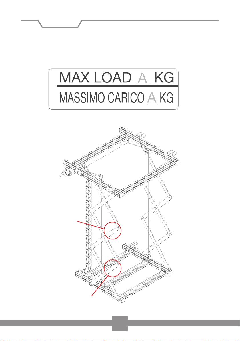
Exceed the maximum load specied
Install and use the lift outdoors
The lift should only be used for the purposes intended. The
manufacturer does not accept liability for injury to people, animals
or damage to objects due to improper or negligent use.
MAKE SURE THAT THE LIFT IS DISCONNECTED FROM THE MAINS
BEFORE STARTING INSTALLATION, CLEANING OR MAINTENANCE
WORK.
Do not remove any warnings or stickers attached to the lift.
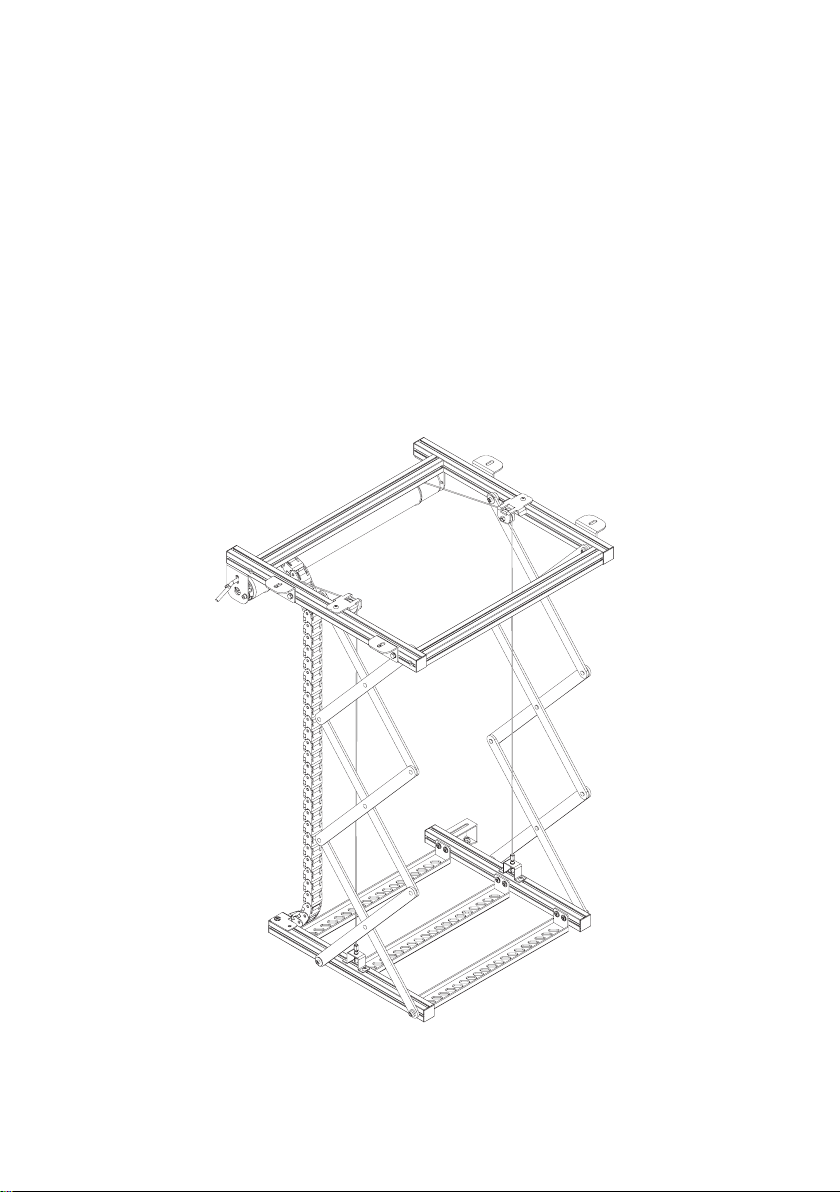
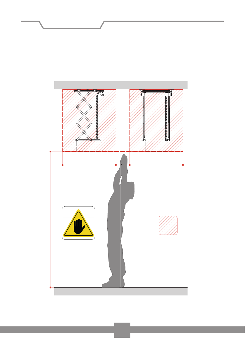
Do not activate the lift if it is not fully assembled and / or safety device is
dismantled or safety warnings are missing.
It is possible to stop the lift at any time by using the up / down switch if
necessary.
In the case of a defect or malfunction, please do not attempt any repairs on the
lift, but contact your dealer or manufacturer.
To connect the lift with the power cable you must follow the instructions in this
manual (see section Electric connections).

7
Description of safety devices
The lift is equipped with two safety screws which are located on the bottom left
prole and the bottom right prole (see illustration below).
The screws can be positioned freely and will prevent the lift from dropping in the
event of a defective rope.
Warning: Once the lower stop
position point has been set, x
both safety screws tightly with an
allen key at a distance of 10mm
from the scissor joint.
10 mm

8
Residual risks (rs)
Please ensure that no people, animals or objects are underneath the lift or near the
area that the lift needs to move in and out when the lift is in use.
The drawing below identies the residual risk area which should be avoided when
using the lift and during installation of the projector.
Minimum height including ceiling tile H = 2.75m
Minimum height excluding ceiling tile H = 2.50m
rs
CEILING
L=1,00 ml L=1,00 ml
FLOOR

9
General description of the projector lift
The following drawing provides an overview of the main components of the lift:
Ceiling mounting
bracket 40x40x60 (mm)
Left structural prole
30x30 (mm)
Left structural prole
30x30 (mm)
Front structural prole
30x30 (mm)
Closing plug for
prole 30x30 (mm)
Braided steel cable
covered with PVC
Left stabilizing
scissors
Back structural prole
30x30 (mm)
Right structural prole
30x30 (mm)
Right structural prole
30x30 (mm)
Cable regulator
Bracket motor
roller tube
Fix pulley
Motor roller tube
Right stabilizing
scissors
Safety screw
Plate for xing
the projector
Cable
management
system

885
45
970
554
22460
70
45
155
554
22460
10
Side view
Side view
Rear view
Rear view
Fig: Lift retracted (mm)
Fig: Lift extended (mm)
Power
supply
Power
supply
575
485
40 40
655
575
485
40 40
655
Dimensions

11
Motor specications
GAPOSA motor, series XQ50P
Cod. XQ5P1017
Tubular motor with mechanical end stop points
Power supply: 230 V
Frequency: 50 HZ
Length of cable: 2.5 m
Cross-section lead: 4 x 0.75 mm²
Operating temperature: -10°C / 40°C
Thermal protection: 4 min.
IP protection class: 44
Torque: 10 Nm
Speed: 17 UpM
Max. power consumption: 184 W
Current consumption: 0.8 A
Box lid
Adesive tape
Polystyrene
sheet
Projector
lift
Polystyrene
edges
Box bottom
Technical specications
Dimensions ‘lift retracted’: 575 x 155 x 554 mm (WxHxD)
Dimensions ‘lift extended’: 575 x 970 x 554 mm (WxHxD)
Max size area of projector xing points: 380 x 400 mm (WxD)
Max projector size: 570 x 600 mm (WxD)
Max load: 30 kg
Net weight of projector lift: 12 kg
Cable management system (inside): 20 x 18 mm (WxH)

12
Installation
Please check PRIOR to installation that you have received all the components listed
below. In case one or more parts are missing, please contact your dealer from
whom you purchased the product.
4 x L brackets for ceiling mounting
with 8 screws and 8 washers
Installation and user guide
4 x M6x25mm threaded rod 12 x M6 nuts
4 x M6 threaded sleeves 4 x M6 screws for
connecting false ceiling
tile
4 x M6x10 Hex head screws
4 x sliding brackets to support false ceiling
rods
1 x wall mounted switch

13
Installation
Do not remove the transport safety protection until the ceiling lift
has been mounted. The spacers ensure the required tension of the
wire ropes.
Ceiling Installation
Attach the L brackets (A) to the frame
proles. Use the appropriate screws and
washers. The nuts are already in the frame
proles (left and right).

14
Installation
For a safe installation, it is recommended
to position the L brackets similar as per the
illustration. We assume in this manual that
the installation is to a at and horizontal
ceiling. Please use a spirit level to ensure a
horizontal installation.
Measure and mark the position of the
mounting points on the ceiling. The ceiling
should be clean and at.
Drill the four holes into the ceiling tting
your screws and wall plugs (not supplied). We
recommend: ø 8mm
Mount the upper frame prole onto the ceiling.
Please verify that the lift is perfectly horizontal
to ensure silent and safe movement.
60
115 mmmm
L
P

15
Installation
Electrical connection
Once the lift has been mounted on the
ceiling, remove the transport safety
protection.
Fixing screws
Electric panel
Switch base
1
2
Switch face
1 Remove the up / down switch face by pulling it upwards. Please do not use any
tools to avoid causing damage
2 If necessary, loosen the screws, turn the switch face and remove it from the
electric panel of the switch
The wall switch can be used with the provided switch base (A) or the electric panel
can be ush mounted to the wall (B).
Wall switch

16
Electrical connection
1: Blue (Neutral)
2: Brown (Live)
Select the power cable in accordance with power consumption of the lift. The
cable should be protected against high temperatures, oils, sharp edges and being
crushed by other components. The following illustration shows the electrical
connection to the supplied wall switch.
A
B
Installation and maintenance work may only be carried out by
qualied personnel with technical and electrical expertise.
3: Black (Live)
: Yellow/green (Earth)
21281L
N
F
CEBEC
1368
K
EMA
EUR D E
V
10A / 250
1
3
2
2
2

17
Setting up the stop positions
You can adjust the stop position points with the allen key adjusting points to
meet your requirements. Please carry out this step with the lift ONLY without the
projector or ceiling tile attached.
Upper Stop Position (when projector is in ceiling)
PLEASE NOTE: The upper stop position comes supplied in its highest
position and being moved higher could seriously damage the lift.
To lower the upper stop
position and get the ceiling tile
level with the ceiling you must
turn the rear adjuster clockwise.
If you have lowered the lift too
much then you can turn the
adjuster anticlockwise to make
it stop higher.
Please adjust in very small
increments and test the
progress after every adjustment
by operating the lift.
Lower Stop Position (when
projector is down)
To make the lift stop higher
when the projector is down,
turn the front adjuster
clockwise. Or if you need to
make the lift drop to a lower
position – turn the front
adjuster anticlockwise.
Again, please adjust in very
small increments and test the
progress after every adjustment
by operating the lift.

18
Installation of the projector
Group together the cables into the plastic
spiral cable management system (K). Please
ensure that it does not get caught in the
scissor joint or motor shaft when the lift is
moving.
Danger:
Only exible cables should be used. Do not use cables that cannot
be bent easily. Only attach cables when the lift is fully extended.
When you mount the projector to
the lift, the lift has to be completely
extended. Attach the projector to the
proles using appropriate screws (not
supplied).
Please ensure that the projector is
installed with the centre of gravity in
the centre of the lift.
Please ensure that the projector is
aligned completely horizontal using a
spirit level to check.
Table of contents
Other Celexon Scissor Lift manuals
Popular Scissor Lift manuals by other brands

Esco
Esco miniLIFT Lift & Move Operating and maintenance manual

Genie
Genie GS-3384 Service manual

Haulotte Group
Haulotte Group OPTIMUM 6 Operating and maintenance instructions

CLAS
CLAS PE 6002 manual

TLS
TLS TLSS10ALOFRR1 Installation, operation & service parts manual

WERTHER INTERNATIONAL
WERTHER INTERNATIONAL SATURNUS 50R Original instructions