Celina MASTER SERIES User manual

20’ x 30’ MASTER SERIES HIGH PEAK
FRAME TENT SECTIONAL PRODUCT MANUAL
Read this manual before using this product. Failure to do so can result in serious injury.
SAVE THIS MANUAL
The warnings, cauons, and instrucons discussed in this instrucon manual cannot cover all possible condions
and situaons that may occur. It must be understood by the user that common sense and cauon are factors
which cannot be built into this product, but must be supplied by the installer and/or user.
Tent, canopy, structure, and shelter products are manufactured for use as temporary structures and do not meet
structural code unless specied. Since weather is unpredictable, the installer/end user must incorporate their
own good judgment, common sense and knowledge of local condions with the installaon instrucon guide-
lines. The installer is responsible for ancipang weather severity for proper me and method of installaon.
This is the safety alert symbol. It is used to alert you to potenal personal injury hazards.
Obey all safety messages that follow this symbol to avoid possible injury or death.
Indicates a hazardous situaon which, if not avoided, could result in death or serious injury.
Indicates a hazardous situaon which, if not avoided, could result in minor or moderate injury.
ver.20150220
NOTICE
WARNING SYMBOLS AND DEFINITIONS
A Division of
SAFETY MAINTENANCEINSTALLATION CONTACTS

20’ x 30’ Master Series High Peak Frame Tent www.GetTent.com / www.CelinaTent.com PG.2
© 2013 Celina Tent Inc.
Descripon
20’ x 30’ Master Series High Peak Frame Tent, Seconal
The Master Series High Peak Frame Tent combines the ease and speedy in-
stallaon of the standard Master Series Frame Tent system with the elegant
appearance and design of a high peak tent. Just like the standard Master
Series Frame tents, The Master Series High Peak is made with fewer pieces
of hardware and a tensioned valance for a smooth, ght appearance. The
high peak and sloping curves catch aenon, while the frame itself can be
interchanged with other Master Series Frame Tents and even the Classic
Series Frame Tent systems.
Suggested Equipment
Drop cloth or ground cloth, sledge hammer, or electric / gas breaker hammer ed with stake driver bit,
stake puller, and frame tent jack/ li.
Colors available by special order
White & Red (5051)
White & Green (5052)
White & Blue (5053)
PRODUCT SPECIFICATIONS
SAFETY MAINTENANCEINSTALLATION CONTACTS
Master Series High Peak Frame Tent Specicaons
Width 20 . / 6.1m
Length 30 . / 9.1m
Area 600 ² /55.5m²
Eave Height 8’ / 2.4m
Overall Height 17’10”/ 5.4m
Pitch 9’10” / 3m
Complete Weight Aluminum 792 Lbs. / 359 Kg.
Complete Weight Galvanized 900 Lbs. / 408 Kg.
Complete Weight Alum. Hybrid
1029 Lbs. / 467 Kg.
Series / Brand Master
Class Frame
Center Pole Peak Extension Pole
Style / Shape High Peak
Expandable Yes
Custom Prinng Available No
Fabric Material PVC Coated Polyester
Fabric Material Weight 16 oz. / yd2 / 540 gsm
Fabric Translucency Blockout
Water Repellency Waterproof
Flame Resistant Yes
UV Resistant Yes
Mold and Mildew Resistant Yes
Frame / Pole Material Aluminum OR Galvanized
Longest Component 14’4” / 4.4m
Persons required for setup 2-5
Occupancy 60 Sit Down Dinner - 100 Cathedral Seang

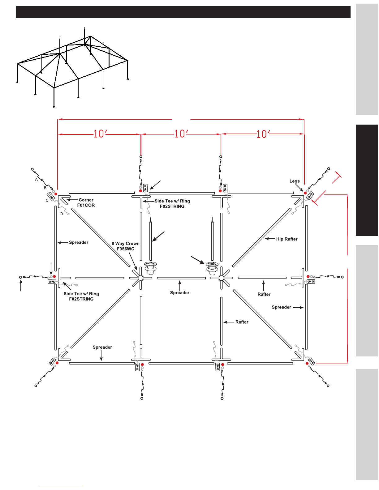
20’ x 30’ Master Series High Peak Frame Tent www.GetTent.com / www.CelinaTent.com PG.3
© 2013 Celina Tent Inc.
Site selecon is extremely important. The installer must adhere to local building codes and re regulaons. The
installer must evaluate each installaon site and determine the proper securing and anchoring method and
device appropriate for the condions. Some soils require dierent staking or securing methods than what may
be/have been purchased with the standard tent package. Celina Tent’s instrucons, YouTube videos, and Layout
Handbook summarize all the funcons of each product, the rules for using them and suggesons for their use.
However, eld situaons, site condions, weather and local experience may mandate other methods. Review
the following condions at the proposed site and plan accordingly.
The best site qualies are:
• Locaon: Elevated, level, and clear of debris
• Soil Condions: Adequate for stable anchoring
• Space: Adequate space for the perimeter and stake lines
• Surface Type: Grass, Gravel, Concrete, Asphalt, Wood
• Site Access: Materials and services can easily be delivered to the site
Also allow for:
• Overhead Obstrucons: Electrical/telephone lines, tree branches
• Underground Ulies: Electric, Gas, Oil, Steam, Telephone, CATV, Water, Sewer
• Weather Eects: Monitor for extreme weather condions and evacuate if necessary
• Emergency Exit Capabilies: Provide evacuaon routes in case of a re or bad weather
SITE SELECTION
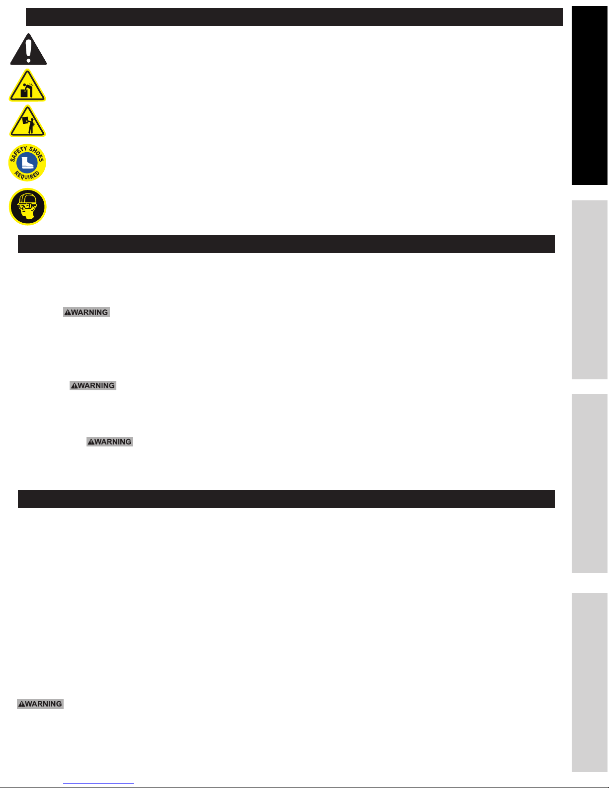
STAY ALERT: Watch what you are doing, and use common sense when installing/striking a tent, canopy,
structure, or shelter. Do not setup/strike while under the inuence of drugs, alcohol, or medicaon. A
moment of inaenon may result in serious personal injury.
DO NOT OVER LIFT: The equipment may be heavy and may require 2 or more people to li and move.
DO NOT OVERREACH: Keep proper foong and balance at all mes. Use a ladder when necessary.
DRESS PROPERLY: Do not wear loose clothing or jewelry. Contain long hair. Keep hair, clothing, and hands/
gloves away from power equipment and snag or pinch points.
USE SAFETY EQUIPMENT: Eye protecon, safety shoes, hard hats, or hearing protecon must be used for
appropriate condions.
Since weather is unpredictable, the installer/end user must incorporate their own judgment, common sense and
knowledge of local condions with the installaon instrucon guidelines. The installer is responsible for anci-
pang weather severity for proper me and method of installaon.
• Rain: Rain water can collect on the tent fabric and cause ‘ponding’ or ‘water pockeng’ under cer-
tain weather condions, especially if the tent is not installed and tensioned correctly. The addional weight
from the water will cause the tent to sag and ponding will connue to get worse. The weight can destroy the
tent fabric and/or cause the poles and baseplates to sink into the soil. Highly saturated soil will cause the
stakes to lose their holding power.
• Wind: Wind or wind and rain can cause the tension of the tent to change by loosening ratchet
assemblies, pulling stakes, and or causing the poles to shi or sink. It is very important to do roune main-
tenance checks and maintain proper tension on the tent top at all mes especially if weather condions are
such that ratchets are beginning to loosen.
• Lightning: Immediately evacuate the tent unl the chance of a lightning strike is no longer present.
• Snow: Tents, canopies, structures, and shelters are not designed to carry any type of snow loading. These
products should not be used if snow of any kind is present, and must be evacuated immediately.
PERSONAL SAFETY
WEATHER
SAFETY MAINTENANCEINSTALLATION CONTACTS

20’ x 30’ Master Series High Peak Frame Tent www.GetTent.com / www.CelinaTent.com PG.4
© 2013 Celina Tent Inc.
A properly driven stake will have 6” or less of the head exposed.
The deeper that the stake is driven, the greater holding strength the
stake will have. Anchoring stakes must be driven deep and vercal.
Stakes driven vercally have a greater holding strength than stakes
driven at an angle. Vercally is dened as straight up down or an-
gled up to 10° away from the tent, canopy, structure, or shelter.
Before You Stake
By law you are required to contact your local “Call before you dig” number before you plan to dig or drive tent
stakes / anchors. Aer calling, your local ulity companies will mark the locaon of all underground ulity lines.
Laws from state to state vary on how far in advance you must call. Planning ahead and checking with your state’s
program is always a smart idea. Failure to obtain a ulity line locaon before digging can result in a substanal
ne or serious injury. Please nd your local “call before your dig number” in the contacts secon of this manual.
Prior to staking, be sure that no underground ulies are present. Celina is not responsible for meth-
ods that installers may choose to erect and secure the tent, canopy, structure, or shelter to the site surface. Celi-
na’s responsibility is limited to the manufacture of the tent parts and materials. It is the installer’s responsibility,
not Celina’s, to determine the appropriate number of stakes to meet the necessary wind loads on the installaon
site.
Soil and setup condions can vary greatly between installaon sites. It is the installer’s responsibil-
ity to be sure the staking is adequate for each site on each setup. Addional staking, ebacks, and/or stake
bars may be required in order to safely setup and secure the product.
The number of stakes suggested in this manual rounely does not meet the relevant local codes of
the installaon site. The number of stakes included in the standard kit will, in most cases, keep the tent, canopy,
structure, or shelter setup. Due to various soil condions the standard staking kit may be inadequate to keep the
tent secure in high winds and wet or threatening weather. Regardless of the number of stakes included in stan-
dard kits, Celina makes no representaon or warranty as to whether this is sucient to meet the requirements
for your installaon site(s).
Staking Basics
STAKING / ANCHORING
SAFETY MAINTENANCEINSTALLATION CONTACTS
For more informaon on staking and soil condions, please view Celina Tent’s 15 part video
series on YouTube.com or follow this link: Stake Pull Demonstraon (1/15) www.goo.gl/v0XhV
6” or less
6” or less

20’ x 30’ Master Series High Peak Frame Tent www.GetTent.com / www.CelinaTent.com PG.5
© 2013 Celina Tent Inc.
REQUIRED HARDWARE
SAFETY MAINTENANCEINSTALLATION CONTACTS
20’ x 30’ Master Series High Peak Frame Tent, Seconal
Descripon (Key) Size/ Color Qty. Picture
Hip Raer 14’4” / Red 4
Raer 10’6” / Green 6
Spreader 9’4” / White 11
Peak Extension Pole 4’9” 2
Legs 7’8” / Black 10
Corner 4
Top ViewSide View
Side Tee w/ Ring 6
Top View
Side View
6 Way Crown 2
Crown Adapter 2
Master Series Base Plates 10
Top View
Side View
R Pin OR Pin & Bail 72
OR
A. Ratchet Buckle with
Loop Strap
2” Ratchet w/
5’ Strap/Loop
10
B. Loop Strap 8’ Strap/Loop 10
Double Head Stakes 36” 10
C. Master Series Ratchet
Buckles Loop Strap w/ O
Ring
1” Ratchet w/
4’ Strap/Loop
10
D. Master Series Loop
Strap
6’ Strap/Loop 10
Double Head Stakes 42” 10
NOTE: When the Ratchet Buckle with Loop Strap (A/C) is connected to Loop Strap (B/D) it forms the Ratchet Assembly.

20’ x 30’ Master Series High Peak Frame Tent www.GetTent.com / www.CelinaTent.com PG.6
© 2013 Celina Tent Inc.
SAFETY MAINTENANCEINSTALLATION CONTACTS
Master Series
Ratchet Assembly
D
C
Descripon (Key) Size/ Color Qty. Picture
Sidewall(s) 20’ 2
Sidewall(s) 30’ 2
OPTIONAL ACCESSORIES
A. Ratchet Buckle with Loop Strap
B. Loop Strap
C. Master Series Ratchet Buckles Loop
Strap w/ O Ring
D. Master Series Loop Strap
Ratchet Assembly
B
A
REQUIRED HARDWARE
RATCHET ASSEMBLIES
Descripon (Key) Size/ Color Qty. Picture
Tent Top 20’x30’ 3 pc.
Tent Bag C 3
Round Boom Tent Bag
Wrap Around Tent Bag
OR

20’ x 30’ Master Series High Peak Frame Tent www.GetTent.com / www.CelinaTent.com PG.7
© 2013 Celina Tent Inc.
SAFETY MAINTENANCEINSTALLATION CONTACTS
PARTS / MINIMUM STAKING LAYOUT
20’ x 30’ Master Series High Peak Frame
Double Head Stake
Double Head Stake
Master Series Base Plates
30’
20’
5’
Peak
Extension
Pole
Crown Adapter
F45MHPCA

20’ x 30’ Master Series High Peak Frame Tent www.GetTent.com / www.CelinaTent.com PG.8
© 2013 Celina Tent Inc.
SAFETY MAINTENANCEINSTALLATION CONTACTS
INSTALLATION INSTRUCTIONS
6. Fasten the loop strap (B) around the ng at each leg locaon.
Set Up Instrucons
1. Lay out the frame parts on the ground in the approximate locaon that they will be when the frame is assem-
bled. (See parts / minimum staking layout diagram)
2. Place the 6-way crown in the framework; the protrusions on the crown will alternate between lied and
touching the ground when it is laid on a level surface. All lied protrusions will point to the hip raers, angled
toward the corners of the tent. The protrusion parallel to the ground will point toward the other 6-way crown.
3. Connect the 6-way crown to the hip raers (14’4” red):
a. Each protrusion on the crown has two holes; one closer to the center (the alignment hole) and one
further down the protrusion (the placement hole).
b. Place a pin in the alignment hole; this keeps the raer from moving too far onto the crown. Slide the
tubing onto the protrusion unl it meets the pin.
c. Align the placement hole in the crown with the hole in the raer and insert a pin.
d. Remove the alignment hole pin. (*This procedure applies to all frame ngs)
4. Connect the rest of the tubing in the following order:
a. Raers (10’6” green) to rst 6-way crown
b. Spreader (9’4” white) to the rst 6-way crown, second 6-way crown to the other end
c. Hip raers (14’4” red) to the second 6-way crown
d. Raers (10’6” green) to the second 6-way crown
e. Corner ngs to hip raers (14’4” red)
f. Side tee ngs to raers (10’6” green)
g. Spreaders (9’4” white) to side tee ngs
h. Spreaders (9’4” white) to corner ngs
5. Bolt the crown adapters into the 6-way crowns.
a. Insert a bolt through the three holes on top of the adapter.
b. Place the adapter through the center circle of the 6 way crown.
c. Slide the ring assembly over the boom of the adapter, lining up the bolts through the holes in the ring.
d. Secure the ring adapter by aaching the nut and lock washers to the bolts.
e. Repeat with other crown adapter.

20’ x 30’ Master Series High Peak Frame Tent www.GetTent.com / www.CelinaTent.com PG.9
© 2013 Celina Tent Inc.
SAFETY MAINTENANCEINSTALLATION CONTACTS
INSTALLATION INSTRUCTIONS
7. Roll out a drop cloth to protect the tent top of dirt and abrasions next to the frame and unroll the tent top
pieces. The tent needs to be laid out in the sequence of: 20x10 lace end, 20x10 midsecon, 20x10 grommet
end. (The midsecon has a lace and grommet side; each seam requires one lace line and one grommet line for
fastening.)
10. Loop the perimeter cord around the outside post of each corner.
8. Lace the tent together:
a. Line up each tent secons (the lace end will always be on the boom) so that they overlap.
b. Starng in the middle and working toward the edge pull the rst lace up through the rst small
grommet. Pull the second lace up through the second grommet, then through the loop of the rst lace.
c. While lacing the tent, be sure to connect the rain ap to the rope covering the lace line. This
eliminates the need to crawl on the tent aer it has been laced.
d. Connue in this fashion unl the third grommet from the edge of the tent is reached. The third lace
should be twice as long as the other loops (this is referred to as a double loop).
e. Pull the nal two lines through the grommets and loop the second lace from the tent perimeter
into the rst lace (the lace is now going towards the direcon of the double loop). Pull the third lace
(double loop) through the second loop. The third lace (double loop) should now be strung through 2
loops (the second loop and the fourth loop).
f. Tie o just past the third grommet; this secures the enre lace line.
g. Connect the hook and loop located on the valance secon at the end of each lace line.
h. Repeat this method to secure all other lace lines.
9. Pull the tent top over the frame, liing up on the fabric or “apping” it to create a cushion of air. Be careful
not to snag the tent top on the center pole pin. Make sure the tent top is centered.

20’ x 30’ Master Series High Peak Frame Tent www.GetTent.com / www.CelinaTent.com PG.10
© 2013 Celina Tent Inc.
15. Step on the master series base plate to free both hands and li one side of the tent frame. Do not li one
corner at a me; li the enre side of the tent. Insert corner ngs into the top of the leg, securing with a pin.
Insert all pins from the outside in; this keeps the protruding secon of the pin from puncturing the tent fabric.
Make sure the staking hole on the base plate is on the outside of the tent.
SAFETY MAINTENANCEINSTALLATION CONTACTS
INSTALLATION INSTRUCTIONS
12. Fasten the master series loop strap (D) to each corner and each point where valance curves meet by pulling
the strap through the two metal rings on the tent top, then through the end loop and ghtening.
13. Aach the master series base plates to the legs (7’8” black) by sliding the leg tubing over the longer protru-
sions on the master series base plates, securing with a pin.
16. Connect the O-ring of the master series ratchet buckle (C) to the base plate hook mounted on the small tub-
ing of the base plate. Feed the master series loop strap (D) aached to the tent top through the reel bars slot of
the ratchet (ratchet buckle needs to have handle facing upward at all mes) and pull the strap back towards the
tent approximately 1 ½ feet. Hold the strap at this point with one hand and begin to crank the ratchet handle
back and forth.
11. The 4’9” peak extension pole is now ready to be set. Insert the pole pin through the ring assembly in the tent
top. Be sure not to pinch or puncture the tent top fabric. Place the boom of the center pole through the crown
adapter. Lining up the center hole on the pole with the hole on the adapter, secure the center pole to the crown
adapter with a bolt and nut. Repeat with the other peak extension pole.
14. In windy condions, locate the downwind side of the tent to li rst; this keeps the wind from catching the tent.

20’ x 30’ Master Series High Peak Frame Tent www.GetTent.com / www.CelinaTent.com PG.11
© 2013 Celina Tent Inc.
SAFETY MAINTENANCEINSTALLATION CONTACTS
INSTALLATION INSTRUCTIONS
20. Make sure the legs are straight then secure the master series base plates by driving a double-headed stake
through the smaller tubing on the master series base plate. Tighten all ratchet assemblies.
21. Roll excess ratchet straps and secure into the ratchet buckle.
17. Repeat with the other side of the tent. When nished with the corner legs, install all other legs at side tee
ng locaons. Pull the anchoring devices (ratchet buckle strap) through the tops of the hook and loop exten-
sions on the tent top to provide access to the stakes.
18. Place stakes 5’ out from each leg; drive stakes into the ground so that approximately 6” or less of the stake
is showing.
19. Aach the ratchet buckle with loop straps (A) to the stakes by turning the 6” loop at the end of the ratchet
inside out and pull the strap through the loop to create a noose and pull ght over the stake. Take the loop strap
(B) aached to the tent and pull it through the reel bars slot of the ratchet (ratchet buckle needs to have handle
facing upward at all mes) and pull the loop strap (B) back towards the tent approximately 1 ½ feet. Hold the
strap at this point with one hand and begin to crank the ratchet handle back and forth.
22. The tent top should now be complete. If sidewalls are desired, unroll the sidewalls between the stakes and
the legs around the perimeter of the tent. Starng at a leg, clip the sidewall snap hooks to the rope line that is
aached to the tent top.
Sidewall Rope Tensioning: For new tents and during its life cycle, it may be necessary to ghten the sidewall
support rope that runs the perimeter of the tent top. Aer the tent has been set up and tensioned, locate the
corner where the sidewall rope starts and stops. Securely e o one end of the rope. While pulling against the
e-o point, work your way around the perimeter of the tent, pulling out any unnecessary rope slack. Tie o the
opposite end of the rope once reached.

20’ x 30’ Master Series High Peak Frame Tent www.GetTent.com / www.CelinaTent.com PG.12
© 2013 Celina Tent Inc.
Striking Instrucons
1. Loosen all ratchet assemblies.
2. Remove the stakes from master series base plates.
3. Remove the interior side tee ratchet assemblies.
4. Remove the side legs leaving the 4 corner legs.
5. Unfasten all anchoring devices from the perimeter tubing (with the excepon of 2 at each corner).
6. Remove 2 corner legs from one side and carefully set the tent frame on the ground.
7. Remove the peak extension pole(s).
8. Remove the 2 remaining corner legs and carefully set the tent frame on the ground.
9. Unfasten the rest of the straps, completely disconnecng the tent top from the frame and stakes.
10. Roll out a drop cloth next to the frame.
11. Carefully remove the tent top from the frame, liing up on the fabric or “apping” it to create a cushion of air.
12. Unlace the tent top:
a. Separate the valance hook and loop that connects the tents together. Unclip the rain ap unl the
lace line e-o is accessed.
b. Une knot and unlace the tent top secon while disconnecng the rain ap.
13. Fold and roll the tent top as ght as possible. Remember not to stand or walk on the tent top fabric.
14. Bagging (always use a drop cloth to protect the tent top from dirt and abrasions while bagging):
a.For Wrap-Around Tent Bag:
i.Lay the bag next to the tent top with the side-release buckles facing down. Roll the tent top
onto the center of the bag.
ii.Connect the two short male and female side-release buckles; pull ght.
iii.Connect the remaining side-release buckle and pull ght.
b. For Round-Boom Bag:
i. Place the folded tent top into the upright vercal posion.
ii. Pull the round boom tent bag over the upright tent top.
iii. Turn the tent top and bag over, pull the draw string ght and e o.
15. Fold and roll up the drop cloth.
16. Remove the crown adapter from the crown ng. Disassemble all of the corner, side tee, and crown
ngs by removing the pins and sliding the tubing o of the ngs. Work from the perimeter of the frame
inward.
17. Remove remaining stakes.
SAFETY MAINTENANCEINSTALLATION CONTACTS
INSTALLATION INSTRUCTIONS

20’ x 30’ Master Series High Peak Frame Tent www.GetTent.com / www.CelinaTent.com PG.13
© 2013 Celina Tent Inc.
For maximum life of Celina fabrics, Celina recommends regular cleaning with the use of a so brush with neu-
tral soaps or cleaners, such as Celina Cleaning Products, Ivory dish soap, or warm water. Thorough rinsing and
drying is required before storing the fabric.
Things that will cause premature degradaon and may reduce life expectancy of a tent:
• Improper handling during installaon/dismantling on rough surfaces will create pinholes and abrasions.
ALWAYS USE A DROP CLOTH/GROUND CLOTH DURING INSTALLATION AND DISMANTLING.
• Walking on the fabric during installaon/dismantling will create pinholes and abrasions.
• Extended use of the tent without cleaning
• Accumulaon of dirt on the vinyl surface will promote the growth of mold and mildew and premature wear.
• Storage of vinyl that has not been dried thoroughly. Even a slightly damp product can promote the growth
of mildew when folded and stored. Mold and mildew may require harsh cleaners to remove, which may
cause premature wear. The best soluon is to take every precauon to keep mold and mildew from growing
in the rst place. NEVER STORE A TENT, CANOPY, STRUCTURE, OR SHELTER IN A WET OR DAMP CONDITION.
• Harsh detergents and cleaners, which contain a solvent or bleach. The longer the exposure of PVC vinyl to
these products, the more it will reduce the life of the PVC vinyl.
• High-abrasive cleaners, including wire brushes, power wasters and/or commercial washing machines will
result in premature wear and deterioraon of tent fabrics.
• Wind whip – Loosely tensioned fabric that whips in the wind will damage over me.
Vinyl Repair
Celina’s repair products provide an easy soluon to tears, punctures, or holes. Repair kits and tools are avail-
able online at www.GetTent.com or by contacng Celina.
Celina Tent Inc. warrants that this product will be free from defects in material and workmanship for a period of
one (1) year following the date of purchase. Defects are limited to any defect which is a result of the manufac-
turing process. Excluded are holes, punctures, or other damages which can be caused during normal installaon
of a tent whenever proper procedures are not followed. Celina at its opon will repair or replace this product or
any component of product found to be defecve during this warranty period. This warranty is valid for the origi-
nal purchaser only, and is not transferable. This warranty does not cover normal wear or damage resulng from
negligent use or misuse of the product, use contrary to instrucons, repairs or alteraons by anyone other than
Celina, or forces of nature. Celina Tent is not responsible for methods that installers may choose to erect and se-
cure the tent to the ground. Celina’s responsibility is limited to the manufacture of the tent parts and materials.
This warranty is in lieu of all other warranes, and there are no warranes, expressed or implied, including war-
ranes of merchantability of tness for a parcular purpose, which extend beyond the descripon on the face
hereof. Celina Tent Inc. shall not be liable for any incidental or consequenal damages. Some jurisdicons do not
allow the exclusion of implied warranes or the imitaon on incidental or consequenal damages, so the above
exclusions and limitaons may not apply to you.
Celina fabrics are inherently ame resistant. Open ames should never be used under any tent, canopy, structure,
or shelter. Fabrics meet or exceed one or more of the following ammability specicaons:
NFPA-701 CPAI-84 ASTM D 6413
BS 5438 BS 7837 (1996) DIN 4102-B1
TENT CARE
PRODUCT WARRANTY
FLAME RESISTANCE
SAFETY MAINTENANCEINSTALLATION CONTACTS

20’ x 30’ Master Series High Peak Frame Tent www.GetTent.com / www.CelinaTent.com PG.14
© 2013 Celina Tent Inc.
STATE CENTER PHONE
Alabama Alabama Line Locaon 800/292-8525
Alaska Locate Call Center of Alaska 800/478-3121
Arizona Arizona Blue Stake 800/782-5348
Arkansas Arkansas One Call System 800/482-8998
California Underground Service Alert 800/227-2600
Colorado Ulity Nocaon Center of Colorado 800/922-1987
Conneccut Call Before You Dig 800/922-4455
Delaware Miss Ulity of Delaware 800/282-8555
Florida Call Sunshine 800/432-4770
Georgia Ulies Protecon Center 800/282-7411
Hawaii Underground Service Alert North 800/227-2600
Underground Service Alert South 800/227-2600
Idaho Palouse Empire Underground 800/822-1974
Ulies Underground Locaon Center 800/424-5555
Dig Line 800/342-1585
One Call Concepts - Idaho 800/626-4950
Shoshone County One Call 800/398-3285
Illinois Chicago Ulity Alert Network 800/892-0123
Indiana Indiana Underground Plant Protecon 800/382-5544
Iowa Underground Plant Locaon Service 800/292-8989
Kansas Kansas One-Call Center 800/344-7233
Kentucky Kentucky Underground Protecon 800/752-6007
Louisiana Louisiana One Call System 800/272-3020
Maine Dig Safe - Maine 888/344-7233
Maryland
Miss Ulity 800/257-7777
Miss Ulity of DESMARVA 800/282-8555
Massachuses Dig Safe-Massachuses 888/344-7233
Michigan Miss Dig System 800/482-7171
Minnesota Gopher State One Call 800/252-1166
Mississippi Mississippi One Call System 800/277-6477
Missouri Missouri One Call System 800/344-7483
Montana
Ulies Underground Locaon Center 800/424-5555
Montana U-Dig 800/551-8344
Nebraska Diggers Hotline 800/331-5666
Nevada Underground Service Alert North 800/227-2600
New Hampshire Dig Safe-New Hampshire 888/344-7233
New Jersey Garden State Underground 800/272-1000
New Mexico
New Mexico One Call System 800/321-2537
Las Cruces-Dona Ana Ulity Council 888/526-0400
STATE CENTER PHONE
New York Dig Safely New York 800/926-7962
New York City-Long Island One Call 800/272-4480
North Carolina North Carolina One Call 800/634-4949
North Dakota North Dakota One Call 800/795-0555
Ohio
Ohio Ulies Protecve Service 800/362-2764
Oil & Gas Producers Underground 800/925-2988
Oklahoma Call Okie 800/522-6543
Oregon Oregon Ulies Nocaon Center 800/332-2344
Pennsylvania Pennsylvania One Call System 800/242-1776
Rhode Island Dig Safe-Rhode Island 888/344-7233
South Carolina Palmeo Ulity Protecon Service 800/922-0983
South Dakota South Dakota One Call 800/781-7474
Tennessee Tennessee One-Call System 800/351-1111
Texas
Texas One Call System 800/245-4545
Texas Excavaon Safety System 800/344-8377
Utah Lone Star Nocaon System 800/669-8344
Vermont Blue Stakes Locaon Center 800/622-4111
Virginia
Dig Safe - Vermont 888/344-7233
Miss Ulity of Virginia 800/552-7001
Miss Ulity 800/257-7777
Washington
Miss Ulity of DELMARVA 800/441-8355
Nocaon Center 800/424-5555
Ulies Council of Cowlitz County 360/425-2506
UpperYakima City Underground 800/553-4344
Inland Empire Ulity Coordinang 509/456-8000
West Virginia Miss Ulity of West Virginia 800/245-4848
Wisconsin Diggers Hotline 800/242-8511
Wyoming
Wyoming One Call 800/348-1030
Call Before you DIg Wyoming 800/849-2476
District of Columbia Miss Ulity 800/257-7777
Canada
Alberta One Call 800/242-3447
Ontario 800/400-2255
Info-Excavaon (Quebec) 800/663-9228
BC One Call 800/474-6886
Manitoba - Winnipeg 240/480-1212
Manitoba & Saskatchewan Safe 800/827-5094
SUPPORT
SAFETY MAINTENANCEINSTALLATION CONTACTS
For technical quesons or replacement parts, please contact:
Celina Tent, Inc. / GetTent.com
5373 State Route 29
Celina, Ohio 45822-9210 USA
Telephone: 419-586-3610
Fax: 419-584-0949
Website: www.GetTent.com
Email: support@celinatent.com
YouTube: hp://www.youtube.com/user/celinatent
Facebook: hp://www.facebook.com/celinatent
Google +: hp://goo.gl/qvVdv
Twier: hp://twier.com/celinatent
LinkedIn: hp://www.linkedin.com/company/celina-tent-fabric-structures
CALL BEFORE YOU DIG OR STAKE
Table of contents
Other Celina Tent manuals

Celina
Celina Pinnacle Manual

Celina
Celina PINNACLE SERIES User manual

Celina
Celina 40' x 80' PREMIERE 1 HIGH PEAK POLE TENT User manual

Celina
Celina KIT-ETS040X040X7' User manual

Celina
Celina BEXLEY SERIES User manual

Celina
Celina CLASSIC SERIES FRAME User manual

Celina
Celina 30’ x 45’ ETS FRAME TENT User manual

Celina
Celina CLASSIC SERIES FRAME User manual

Celina
Celina HGPTS User manual