Cellar Cool CM2500 Evaporator User manual

CM2500
VERSION 2
TECHNICIAN’S MANUAL
NOTICE: To activate the split system warranty,
the installing certied HVAC/R service tech
must complete the split system warranty
checklist and send back to CellarCool.

Copyright © 2012. CellarCool. All rights reserved.
CellarCool copyrights this manual, the product design, and the design concepts, with all rights reserved. Your rights with
regard to the hardware and manual are subject to the restrictions and limitations imposed by the copyright laws of the
USA. Under copyright laws, this manual may not be copied, reproduced, translated, transmitted, or reduced to any printed
or electronic medium or to any machine-readable form, for any purpose, in whole or in part, without the written consent
of CellarCool.
Every effort has been made to ensure that the information in this manual is accurate. CellarCool is not responsible for
printing or clerical errors.
CellarCool reserves the right to make corrections or improvements to the information provided and to the related
hardware at any time, without notice.
Vinothèque and CellarCool are registered trademarks, and ECE is a trademark of CellarCool. All rights reserved.
Mention of third-party products is for informational purposes only and constitutes neither an endorsement nor a
recommendation. CellarCool assumes no liability with regard to the performance or use of these products.
01.04.2017
We manufacture, test and certify 100% of our wine cooling units in
the USA. By sourcing the best components and closely controlling our
manufacturing processes, we can assure the highest-quality,
lowest defect manufacturing rates in the industry.
Conforms to ANSI/UL Std 427
Certied to CAN/CSA Std C22.2 No. 120

TABLE OF CONTENTS
Quick Reference Guide
Knockout Locations ...................................... 8
Display Layout & Specications ........................... 9
Condensing Unit ......................................... 10
Evaporator Installation
Items to Route before Installing the Evaporator Unit....... 13
Selecting Mounting Option .............................. 14
Mounting the Evaporator Unit ............................ 15
Evaporator Unit Preparation .............................. 16
Evaporator Unit Installation .............................. 17
Insulation Blanket Installation ............................ 19
Drain Line................................................... 21
Liquid Thermostat (Bottle Probe)........................... 22
Remote Display Installation ................................ 23
CM2500 Wiring Diagram.................................... 29
CM2500 with Cold Weather Start Kit
Wiring Diagram ............................................. 30
Preparing the Condensing Unit............................. 31
Cold Weather Start Installation ............................. 31
CM2500 Condensing Unit Wiring Diagram ................. 33
CM2500 Condensing Unit with Cold Weather
Start Kit Wiring Diagram.................................... 34
Line Set Piping Diagrams ................................... 35
Installing the Condensing Unit ............................. 36
System Operation. . . . . . . . . . . . . . . . . . . . . . . . . . . . . . . . . . . . . . . . . . . 38
Controller Functions ........................................ 40
Troubleshooting Guide ..................................... 45
Maintenance Schedule ..................................... 47
Bypass Test Procedure ...................................... 48
Technical Assistance & Accessories ......................... 49
Installation Terms and Conditions .......................... 50
Introduction ................................................ 3
Quick Start Guide........................................... 4
Before You Start ............................................ 5
Receiving & Inspecting the System ......................... 6

CMW 070517
Page 2 | 1-855-235-5271
WARNING
The evaporator unit (fan coil unit) must be insulated using the insulation blanket provided in
accordance with this manual. Refer to the insulation blanket installation instructions.
Failure to follow the instructions provided will result in a poor vapor barrier, water
damage, rust, and system corrosion which will void the warranty on your unit.
The evaporator unit (fan coil unit) must be insulated using berglass insulation (R13 or higher)
in addition to the provided insulation blanket. This includes the cavity between the ceiling
joists. A warm attic environment will reduce the capacity of the cooling system, as the system
will absorb heat from the attic in addition to the heat load from the wine cellar. This, in eect,
will signicantly reduce the cooling system’s ability to cool the wine cellar.
Failure to properly insulate the evaporator unit may cause condensation to form on the
surface of the housing and water damage to the surrounding structure, the cooling unit, and
possibly the wine cellar.
To avoid these issues, install the insulation kit and insulate the surface of the evaporator unit
that is located outside of the wine cellar using berglass insulation.
*Additional insulation is required!

www.cellarcool.com | Page 3
CM2500
WARRANTY REGISTRATION
In order to activate the warranty of your system, the verication and operational
documentation must be completed by the certied refrigeration technician
installing your system and submitted via mail, fax, or e-mail.
Mail to:
CellarCool
ATTN: Warranty Registration
1738 E. Alpine Avenue
Stockton, CA 95205-2505
USA
Fax to:
209-466-4606
Scan and email to:
warranty@cellarcool.com
INTRODUCTION
Customer Service
Thank you for purchasing a CellarCool cooling system. We strive to provide the highest-quality products and the best possible
customer service. If you have any questions about your system, please call us at 1-855-235-5271 or visit cellarcool.com.
Using the Manual
This owner’s manual is intended to assist in the proper maintenance of the cooling system. In order to ensure the longevity of
your cooling unit, the equipment should be installed as outlined in the technician’s manual. It is also vital to establish a proper
care and maintenance schedule. Please read and review this manual carefully and keep it for future reference.
What is the CellarCool Cooling System?
The CellarCool cooling system is a specialized refrigeration system designed for one purpose only: to maintain the optimal
temperature and humidity levels conducive to the proper storage and aging of ne wines. This system produces minimal in-cellar
noise and has the most lenient exhaust requirements. An exterior housing is required for outdoor condensing unit installations.
How Does the Cooling System Work?
Similar to the air conditioning systems used for homes, the evaporator unit (fan coil unit) and condensing units are installed
in separate locations and are connected by a refrigerant line set. The evaporator portion is commonly installed in the wine
cellar, with the condensing unit is located either outside or in a remote indoor location that is ventilated. An exterior housing is
required for outdoor condensing unit installations.
Temperature Setting
The system is designed to maintain a cellar temperature of 55°F as long as the ambient temperature does not exceed 110°F.

CMW 070517
Page 4 | 1-855-235-5271
Pump Down Cycle
CellarCool’s split systems operate on a pump down cycle dierent from traditional air conditioners. As such, there is no wiring
between the condensing unit and evaporator unit. (However, if the system is equipped with a Cold Weather Start Kit, it will require
two 24-volt wires running from the evaporator unit to the condensing unit.)
CellarCool units utilize a solenoid valve on the liquid line and a low-pressure switch on the suction line. When the thermostat calls
for cooling, the solenoid valve opens, permitting the ow of refrigerant. The low-pressure switch then signals the compressor to
cycle on.
When the cellar reaches the desired temperature and the thermostat is satised, the solenoid will close, stopping the liquid
refrigerant ow to the TXV valve. The compressor will continue to operate until most of the refrigerant on the low side boils o
and is pumped through the compressor into the condenser coil and receiver. As the suction pressure falls below the pressure
control setting, the low-pressure switch will signal the compressor to cycle o. Most of the refrigerant is now stored between the
condensing unit and receiver.
Cold Weather Start Kit
If you are installing a unit equipped with the optional cold weather start kit, run two low-voltage wires from the evaporator unit to
the condensing unit.
…………………………………………………………………………………………………
WARNING: Do not utilize a ground fault interrupter, as it will prevent
the unit from drawing the necessary amperage to start the unit.
QUICK START GUIDE*
TXV Adjustments
A. A TXV adjustment may be necessary based on ambient temperatures in the cellar and at the condensing unit.
B. Adjust the TXV until the superheat is between 8-12°F degrees (measured at the outlet of the evaporator coil).
C. Under normal operation, with the wine cellar at 55°F and the ambient temperature at 85°F, the low side pressure should be
between 28-32 PSI and the high side should be between 170-180 PSI.
*Further system operation information is available on page 38.
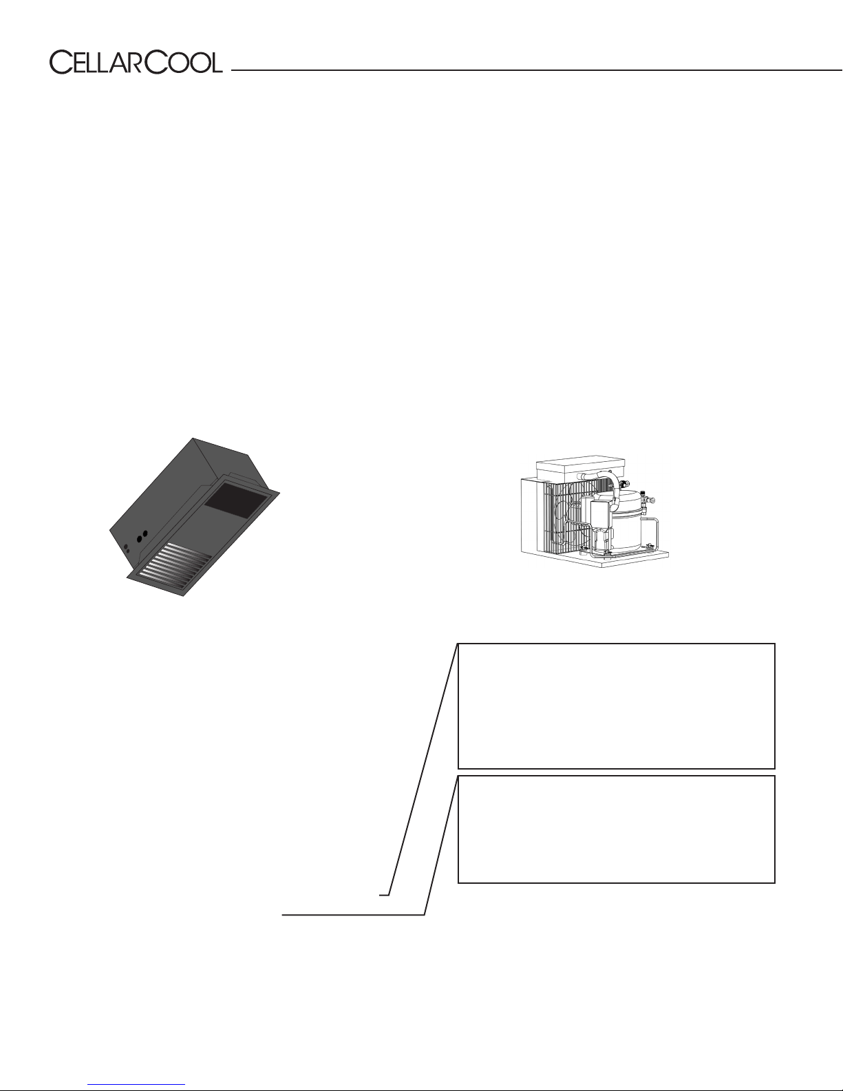
Liquid Line King Valve
This location is used to charge the system with liquid refrigerant
and identify the high side pressure of the system.
Calculating Subcooling
To determine the subcooling of the system, calculate the dierence
between the high side pressure of the system (converted to
temperature) and the temperature of the liquid line. The temperature
of the liquid line will be taken at the outlet of the receiver.
*Saturation temp — liquid line temp
5-9°F SUBCOOLING REQUIRED FOR WARRANTY APPROVAL
TXV
The TXV is preadjusted at the factory. If the superheat is not
within 8-12°F, the TXV will need to be adjusted.
ADJUSTING THE TXV
Use a ⁄”hex key to remove the cap from the TXV superheat
adjustment port. With the cap removed, insert the hex key into
the superheat adjustment port. Increase superheat by turning
the hex key clockwise. Decrease superheat by turning the hex
key counterclockwise.

www.cellarcool.com | Page 5
CM2500
www.cellarcool.com | Page 5
BEFORE YOU START
1-800-343-9463
1. Inspect all components prior to installation. If damage is found, please contact your distributor or CellarCool Customer
Service at 1-800-343-9463.
2. The evaporator unit and condensing unit each require a dedicated 115V, 20-amp circuit. Use a surge protector with the
unit. Do not use a GFI (ground fault interrupter) line.
3. The evaporator unit and condensing unit require no communication lines unless the system is equipped with a Cold Weather
Start Kit. If the system is equipped with a Cold Weather Start Kit, a low-voltage 18-2 thermostat wire will need to be run
between the evaporator unit (fan coil unit) and the condensing unit.
4. You are REQUIRED to install a drain line to remove condensation from the evaporator unit (fan coil unit).
5. The warranty is not active until a warranty checklist has been received, reviewed, and approved.
6. The system is intended for use in properly designed and constructed wine cellars. Hire a professional wine storage
consultant with a valid contractor’s license to build your wine cellar.
7. CellarCool requires that all split systems be installed by a certified HVAC-R technician only. NATE or equivalent is
recommended.
If you encounter a problem with your CellarCool system, please refer to the Troubleshooting Guide. If you have any further
questions or concerns, or need assistance, please contact CellarCool’s Customer Service at 1-800-343-9463. Please be sure
all testing has been completed prior to contacting Customer Service. Please have your results ready for your representative.

CMW 070517
Page 6 | 1-855-235-5271
RECEIVING & INSPECTING THE SYSTEM
• Use caution when lifting and check package for damage.
• Lift only at the designated hand-hold locations on the shipping container, or fully support the unit from underneath. A
shipment may include one or more boxes containing accessories.
• Before opening the container, inspect the packaging for any obvious signs of damage or mishandling.
• Write any discrepancy or visual damage on the bill of lading before signing.
• Allow the condensing unit to sit for 24 hours prior to start-up. The condensing unit can be placed in the installation
location, piped and evacuated during this time.
Note: CellarCool units are manufactured in the USA and tested prior to shipment.
• Review the packing slip to verify contents.
• Check the model number to ensure it is correct.
• Check that all factory options ordered are listed.
If any items listed on the packing slip do not match your order information,
contact CellarCool Customer Service immediately.
Check all shipped boxes for the following contents:
Please leave the unit in its original box until you are ready for installation. This will allow you to move the product safely without
damaging it. When you are ready to remove the product from the box, refer to the installation instructions.
TIP: Save your box and all packaging materials. They provide the only safe means of transporting/shipping the unit.
Evaporator Unit Box Condensing Unit Box
(1) CM2500 evaporator unit (fan coil unit) (1) CM2500 condensing unit
Evaporator installation hardware bag:
• (12) 2½” Phillips wood screws
• (12) #8 ⁄” Phillips pan-head screws
• (1) Bypass plug
• (1) ¼” barbed coupling
• (2) 3” strip of cork tape
Documentation bag:
• CM2500 Version 2 owner’s manual
• CM2500 Version 2 technician’s manual
• R-134a split system warranty checklist
KDT Plus hardware bag:
• (1) ⁄” OD grommet
• (2) ½” nylon hole plug
• (4) #6 x 1” Phillips zinc Type A screw
• (4) 8-10 x ⁄” blue plastic screw anchor
Accessory kit bag:
• Stainless steel probe (50 feet)
• KDT Plus display cable (50 feet)
• KDT Plus wall mount bracket assembly
• KDT Plus ush mount bracket assembly
• KDT Plus display assembly
• Flush mount template
• Evaporator installation hardware bag
• KDT Plus hardware bag
CM2500 insulation blanket bag:
• CM2500 insulation blanket
Condensing unit accessory kit:
• (1) Filter drier
• (1) Sight glass

www.cellarcool.com | Page 7
CM2500
QUICK REFERENCE GUIDE
Top View
Bottom View
Note: The unit comes in black. The mounting bracket and front grille
are paintable, enabling you to match your desired color.
Electrical Knockout
Options
Line Set Knockout
Options
Mounting Bracket (Paintable)
Supply and Return Grille (Paintable)
Electrical Knockouts
Line Set
Drain Line
Line Set Knockout

CMW 070517
Page 8 | 1-855-235-5271
KNOCKOUT LOCATIONS
Side View 1
Side View 3
Side View 2
Side View 4
10.08”
1”
1”
10.08”
11.08”11.08”
7.55”
7.87”
.32”
1.71”
1.71”
1.5”
1.5”
11.08”11.08”
15.67”2”3.5”
.88”
.88”
1.43”
1.43”
9.91” 9.31” 12.74”
9.03”
11.34”
11.34”
22.05”
22.05”
10.08”
1”
Top View
10.34”
1”
11.34”
22.05”
12.74”
1.17”
1.17”
1”

www.cellarcool.com | Page 9
CM2500
CM2500 SPECIFICATIONS
Model Evaporator
(Fan Coil Unit)
Condenser
(Air-Cooled Condensing Unit)
Cellar Size (cu. ft.) 500
Dimensions 22.05”L x 11.34”W x 11.08”H
(24.55”L x 13.84”H w/mounting bracket) 16.0”L x 11.5”W x 10”H
BTUh with 90° air entering
the condenser coil 1730
CFM 107 190
Refrigerant R-134a
Condensing Unit HP 1/6
Voltage Rating 115V (15-amp dedicated circuit required)
Weight (lbs) 40.6 38.8
AMPS (Starting/Running) 2/1 13.8/3.44
dBA 52 65
Line Set Suction line: ⁄” OD; liquid line: ¼” OD
Drain Line ¼” ID clear plastic tubing
Installation Evaporator unit (fan coil unit) is installed through the cellar ceiling. Condensing unit is
installed up to 100 line ft. from the evaporator unit.
Thermostat Remote digital display
Temp. Delta 55°F max temperature dierential between the cellar and condensing unit intake
temperature
Warranty 2 years (parts and labor)
QUICK REFERENCE GUIDE
Display Layout
Compressor is on
Fan is on
Anti-Frost Cycle
running
Alarm is present
°
F
°
F
View/Change Set Point
Enter User Menu
Unlock Button
(hold for 1 sec)
Scroll Button
Change Set Point
55°F
Power On/O
(hold for 5 sec)
Scroll Button
Change Set Point
Return to Previous
Menu

CMW 070517
Page 10 | 1-855-235-5271
CM2500 CONDENSING UNIT QUICK VIEW*
Electrical Box
Receiver
Liquid Line
Service Valve
Suction Line
Service Valve
Fan Cycling Switch
Cut Out: 75 psi
Cut In: 120 psi
Low Pressure Switch
Cut Out: 5 psi
Cut In: 20 psi
Cold Weather Start Kit
Electrical Box
Low Pressure Switch
Cut Out: 5 psi
Cut In: 20 psi
Fan Cycling Switch
Cut Out: 75 psi
Cut In: 120 psi
*CWSK not shown

www.cellarcool.com | Page 11
CM2500
COLD WEATHER START KIT CONDENSING UNIT QUICK VIEW
Thermal Switch
Receiver Heater
Compressor Contactor
(Magnecraft Relay)
Enclosed Power
Relay
Bypass Timer
Start Assist
(Magnecraft Relay)
COLD WEATHER START KIT
ELECTRICAL SET UP

CMW 070517
Page 12 | 1-855-235-5271
SPLIT SYSTEM CHECK LIST
In order to activate the warranty for this product, the information here must be complete and accurate. Any
incorrect or omitted information will result in a return trip by the installing technician at their cost.
Note: All readings need to be taken while the compressor is running.
DATA RECORDINGS
Line Set Information
A. Line set length:
B. Suction line OD:
C. Liquid Line OD:
Sub Cooling
A. Measure head pressure at liquid line king valve. Convert pressure to temp using conversion chart.
B. Temp of liquid line at king valve:
C. Complete sub cooling calculation: A – B =
Superheat
A. Measure suction pressure at the suction line service valve, convert to temp.
B. Measure the temperature of the suction line at the outlet of the evaporator.
C. Complete superheat calculation: A – B =
NOTE: There may be a need to adjust the TXV to get the correct superheat levels.
Bottle Probe
A. Install probe in bottle of warm water to keep system operating.
Temperature Dierential at the Evaporator
A. Measure return air and supply air temperatures at the evaporator to ensure adequate cooling of air in cellar.
Voltage and Amp Draw
A. Measure voltage to compressor and amp draw.
Charging the System
A. Fill system until bubbles dissipate from site glass.
NOTE: Be careful not to overcharge the system.
Compressor Temperature
A. Measure temperature at bottom of compressor.
NOTE: Cool temp may indicate liquid in the compressor.
Condensation Drain Test
A. Pour water into the drain pan to assure it drains properly.

www.cellarcool.com | Page 13
CM2500
ITEMS TO ROUTE BEFORE INSTALLING THE EVAPORATOR UNIT
Routing Instructions:
1. Route the line set from the condensing unit to the desired evaporator unit installation location.
2. Route the display cable from the desired location to the evaporator unit installation location (see page 23 for more
display information).
3. Route the bottle probe cable from the desired thermostat bottle location to the evaporator unit installation
location (see page 22 for more bottle probe information).
4. Route the drain line from a proper discharge location to the evaporator unit installation location (see page 21 for
more drain line information).
5. Route the power cable wiring to the evaporator unit installation location.
ITEMS TO ROUTE
55°F
POWER CABLE
DRAIN LINE
DISPLAY CABLE
BOTTLE PROBE
LINE SET

CMW 070517
Page 14 | 1-855-235-5271
Minimum Tools Needed:
Fully exposed mounting option
Flush mount option
Choose a mounting
option suitable
for the installation
location.
Partially recessed mounting option
1. Locate the desired installation location. Using a stud nder, locate the ceiling joists on either
side of the center point. Cut and frame an opening in the ceiling measuring 12” x 22.75”.
Make sure the framing is sucient to support the weight of the cooling unit. Use only the
mounting locations provided. These locations ensure that the installer will not drill into any
vital components within the system.
2. Determine which orientation the evaporator unit will be installed in (inside the cellar or with
attic access). Mounting options are listed below:
Hammer Saw
#2 Phillips-head
screwdriver
SELECTING MOUNTING OPTION
T-square
1
2
3
4
11.08”
11.08”
4.3”
4.3”
6.78”
6.78”

www.cellarcool.com | Page 15
CM2500
MOUNTING THE EVAPORATOR UNIT
MOUNTING BRACKET
NOTE: You are REQUIRED to use only the mounting locations provided. These locations
ensure that the installer will not drill into any copper or electrical wiring within the system.
2. Controller & bottle probe wiring
1. Power cable wiring
3. Line set
4. Drain line
Routed Items:
NOTE: If installing the unit without attic access, perform steps 5-24 prior to steps 3-4.
3. Secure the mounting bracket to the unit using the twelve (12) supplied ⁄” Phillips pan-head screws.
4. Secure the unit’s mounting bracket to the opening using the twelve (12) supplied 2½” Phillips-head screws.

CMW 070517
Page 16 | 1-855-235-5271
EVAPORATOR UNIT PREPARATION
5. Unscrew the sixteen (16) screws and remove the top
access panel.
6. Remove the knockout(s) that you will be using to route
the line set, power wires, display cable, bottle probe,
and drain line.
7. Locate the white zip tie securing the drain line tube to
the suction line and cut it. Direct the end of the drain
line away from refrigerant lines.
1. Power cable
2. Controller & bottle
probe wiring
8. Pull tubing out of housing to allow room for brazing.
Make sure tubing protrudes out of the housing and
the drain line is moved out of the way as shown.
NOTE: If installing the unit with attic access, perform steps
5-8 after the unit has been mounted.
CUT THIS ZIP TIE DO NOT CUT

www.cellarcool.com | Page 17
CM2500
INSTALLING THE EVAPORATOR UNIT
9. Remove the protective caps from the liquid and
suction line connection tubes (as shown above ).
10. Using copper tubing per line set sizing chart, route
the liquid and suction lines to the tubing coming from
the unit.
11. Place a wet rag around the suction and liquid lines
approximately 4” from the braze joints. This will
prevent excess heat from damaging components.
12. To prevent oxidation, purge the system with nitrogen.
13. Braze the copper tubing to the connections on the
evaporator unit.
BRAZE LINE SET USING
COUPLING
14. Insulate the suction line using Armaex or similar
insulation.
15. Route the drain line out of the evaporator unit with
the line set. Connect using the supplied ¼”barb
coupling.
16. Route the power wire, bottle probe, and display
cable into the unit.
17. Slide the electrical panel up and out of the unit.

CMW 070517
Page 18 | 1-855-235-5271
18. Connect the green wire to the green wire, the black
wire to the black wire, and the white wire to the
white wire.
19. Connect the end of the bottle probe cable to the
circular connector on the exterior of the electrical
box.
NOTE: The unit comes in black. The mounting bracket
and front grille are paintable, enabling you to match your
desired color.
20. Connect the end of the display cable labeled
“UNIT” to the wire labeled“UNIT” coming from the
electrical box.
21. Slide the electrical panel back into the evaporator
unit.
22. Reinstall the top access panel and fasten the sixteen
(16) screws into place.
23. Install the supplied three-inch pieces of cork tape
around the display cable, bottle probe cable, and
power wires.
UNIT
UNIT
Table of contents