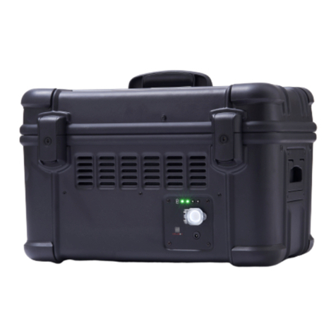
Cellbox Ground 2.0 User manual

4
TECHNICAL MANUAL
Cellbox Ground 2.0

PRODUCED BY
An der Bahn 5
22844 Norderstedt
Germany
T +49 40 226316410
Englische Planke 8
20459 Hamburg
Germany
T +49 40 226316410
cellbox-solutions.com
office@cellbox-solutions.com

TECHNICAL MANUAL
Cellbox Ground 2.0
21 CFR Part 11 Data Security Software License
DISCLAIMER
The manual is intended as a guideline and that Cellbox Solution GmbH shall in no event be held
liable for any direct, or incidental damages that arises out of, or are related to the use of this manual.
Version 1.3, May 2022, Author: Robin Sieg

7
TABLE OF CONTENT
1SAFEKEEPING OF THE MANUAL....................................................................................................................... 8
2DEVICE DESCRIPTION ...................................................................................................................................... 8
3LIST OF USED SYMBOLS.................................................................................................................................. 8
4INTENDED USE................................................................................................................................................. 8
4.1 PURPOSE...................................................................................................................................................................8
4.2 RESTRICTIONS ON THE USE OF THIS DEVICE ...................................................................................................................8
5SAFETY INSTRUCTIONS ................................................................................................................................... 9
6PRODUCT SPECIFICATION ............................................................................................................................... 9
6.1 SCOPE OF DELIVERY ...................................................................................................................................................9
6.2 INSTALLATION.............................................................................................................................................................9
6.3 FEATURES................................................................................................................................................................10
6.4 DEVICE OVERVIEW ....................................................................................................................................................10
6.5 DISPLAY ELEMENTS...................................................................................................................................................11
6.5.1 USER MANAGEMENT .........................................................................................................................................11
6.5.2 SETUP –TEMPERATURE.....................................................................................................................................14
6.5.3 SETUP –CO2CONCENTRATION..........................................................................................................................15
6.5.4 SETUP –CO2CARTRIDGE LEVEL ........................................................................................................................15
6.5.5 SETUP –DATA LOGGING....................................................................................................................................15
6.5.6 DATA EXPORT ..................................................................................................................................................17
6.5.7 SERVICE ..........................................................................................................................................................17
7OPERATION OF THE DEVICE .......................................................................................................................... 18
7.1 POWER ON /POWER OFF ..........................................................................................................................................18
7.2 CHARGING THE DEVICE..............................................................................................................................................18
7.3 EXCHANGE OF CO2MINI CARTRIDGE............................................................................................................................19
7.4 PREPARING THE DEVICE FOR TRANSPORT .....................................................................................................................20
7.5 TRANSPORTING THE DEVICE .......................................................................................................................................20
7.6 SAFE REMOVAL OF LIVE CELLS FROM THE DEVICE ..........................................................................................................21
7.7 CLEANING THE DEVICE ...............................................................................................................................................21
8LABELS ON THE DEVICE ................................................................................................................................ 21
8.1 TYPE PLATE..............................................................................................................................................................21
8.2 LABELING REQUIREMENTS FOR GROUND AND FLIGHT TRANSPORT OF THE CELLBOX ...........................................................21
8.3 PACKAGING OF BIOLOGICAL MATERIALS .......................................................................................................................25
9ENVIRONMENTAL CONDITIONS FOR THE USE OF THE DEVICE...................................................................... 25
10 STORAGE AND DISPOSAL .......................................................................................................................... 25
10.1 STORAGE.................................................................................................................................................................25
10.2 DISPOSAL ................................................................................................................................................................25
11 TECHNICAL SPECIFICATIONS..................................................................................................................... 25
12 MAINANANCE & WARRANTY....................................................................................................................... 25
13 CLEANING INSTRUCTIONS ......................................................................................................................... 26
14 EC DECLARATION OF CONFORMITY........................................................................................................... 27

8
1SAFEKEEPING OF THE MANUAL
The technical manual belongs to the Cellbox Ground 2.0
- 21 CFR Part 11 Data Security Software License - and
must be downloaded digitally. This ensures that persons
operating the device can refer to the content of the man-
ual as required.
The latest version of the technical manual can be
opened by scanning the code on the type plate of the
Cellbox 2.0 or below:
https://cellbox-solutions.com/downloads
2DEVICE DESCRIPTION
The Cellbox 2.0 is an electronic device developed by
Cellbox Solutions GmbH for the safe and documented
transport of living cells. The living cells, which can be
transported in various cell culture vessels, are enclosed
within the incubation chamber of a robust transport trunk.
This creates a controlled environment wherein the phys-
ical parameters, such as the temperature and CO2 con-
centration can be defined and stably maintained for a
period of at least 32 hours without an external power
source.
In order to achieve the optimal conditions for the
transport of living cells, the Cellbox 2.0 is able to control
the ambient temperature around the cell culture vessels
with precision. This function is further supported by the
continuous circulation of air around the cell culture ves-
sels, resulting in an even temperature distribution. The
device also maintains a constant internal CO2concen-
tration by automatically dispensing pure gaseous CO2.
This sustains the vitality of the in vitro cell cultures by
providing a source of environmental CO2that stabilizes
the pH. To ensure that an adequate supply of gaseous
CO2 is available for the entire period of transport, the de-
vice is equipped with a disposable CO2cartridge. Each
disposable cartridge can maintain a 5% CO2environ-
ment for up to 72 hours.
The Cellbox 2.0 can be operated from its built-in re-
chargeable Lithium-Ion Battery packs, an external power
supply or even an automotive/vehicle power adapter
(see chapter 6.1). This provides the user with various op-
tions to ensure an uninterrupted power supply during
transport. Sensors within the transportation compart-
ment of the device log data of the conditions that the
cells (living cargo) experience during transport. These
data logs can easily be transferred to a mobile device
using Bluetooth connectivity to the CELLBOX 2.0 – LIVE
CELL SHIPPER App.
3LIST OF USED SYMBOLS
4INTENDED USE
4.1 Purpose
This device is intended to serve as a protective environ-
ment that can sustain living cells, in various cell culture
vessels, for a defined period of time, with the purpose of
transport. In this context transport can refer to carrying
the device or moving the device with the aid of a vehicle.
When in operation the device can be configured to au-
tomatically maintain a set internal temperature and CO2
concentration.
Power can be supplied to the device by means of an
external power supply or in a portable manner from the
internal battery packs.
The following cell culture vessels are compatible with the
Cellbox Ground 2.0:
•Multiwell-plates with 6, 12, 24, 48, 96 and 384 wells
•Multiwell-plates with standard ANSI/SBS footprint.
•Various chip formats
•Various cell culture bags
•Various cell culture flasks
4.2 Restrictions on the Use of this Device
It is strictly forbidden to transport a device
in operation by aircraft if a mini CO2cartridge is
inserted.
Symbols used on Cellbox
Direct Current
Read the manual
This product is subject to the European
Community Directive 2002/96/EG on
waste electrical and electronic equip-
ment (WEEE).
This product has been tested for electro-
magnetic radiation below the limits spec-
ified by the Federal Communications
Commission.
This product satisfies European harmoni-
sation legislation. (CE Marking)
Symbols used on the Technical Manual
Additional information for the user
Warning: Warning of situations that may
result in personal injury or property dam-
age
Critical Warning: Prohibition of misuse
that may result in personal injury or prop-
erty damage

9
It is strictly forbidden to use the device for the transport
of infectious substances as classified within Class 6.2 of
the ADR (European Agreement concerning the Interna-
tional Carriage of Dangerous Goods by Road, applicable
as from 01.01.2015) as well as Class 3.6.2 of the IATA
(International Air Transport Association - Dangerous
Goods Regulations, applicable as from 01.01.2021).
Use of the device for any purpose other than the in-
tended purpose described in section 4.1 is classified as
misuse and can result in danger or damage.
The device may not be used for the transport of materials
and substances that could produce toxic vapors or ex-
plosive fumes at the set temperature. Furthermore, ma-
terials and substances that pose a risk of exploding,
bursting or igniting may not be transported in this device.
If any doubt arises about the composition of the materials
or substances to be transported, they must not be
loaded in the device.
Potentially explosive gas-air mixtures may not be formed
in the transportation compartment, nor may the device
be operated in their immediate vicinity.
5SAFETY INSTRUCTIONS
The device may only be operated in a good work-
ing order. When the user identifies any irregularities, dis-
turbances or damage before or during the operation of
the device, it should immediately be decommissioned.
After decommissioning the device, the user should con-
tact the manufacturer.
The device may not be rebuilt, modified or altered
in any way without the authorization of the manufacturer.
In the event of any unauthorized modification or altera-
tion, the declaration of conformity is declared invalid and
the device must be decommissioned.
During the transport of unsuitable goods, the pos-
sibility exists that toxic vapors or explosive fumes may be
formed. This may cause the device to explode and result
in serious injury or poisoning. The device is only intended
for the transport of goods that do not form any toxic va-
pors or explosive fumes when heated (also see section
4)
The device must not be sprayed with or sub-
merged in water. As the device is only resistant to low
quantities of dripping water, larger quantities of water
could reach the internal electronics and cause damage.
As a result of partial disassembly or damage to
the casing of the trunk, electrical wires could be exposed
and pose a risk of electric shock to the user. Repairs and
maintenance of the electric components must only be
performed by the manufacturer and authorised partners.
The use of the device in potentially
explosive areas (containing flammable
substances, gases, fumes or mixtures of gas and
air) is strictly forbidden. The device does not have
any measure of explosion protection.
6 PRODUCT SPECIFICATION
6.1 Scope of Delivery
Besides the Cellbox Ground 2.0 the following items are
included in the scope of delivery:
•1x multi-well holder
•3x spacers for multi-well holder
•3x spare disposable CO2cartridges
•1x power adapter for operation of the device or for
charging the battery packs
•1x car adapter
•Technical Manual (Online)
•Power plugs with wall socket compatibility for
EU, Japan, UK, USA, Switzerland and Australia.
6.2 Installation
Place the polystyrene carton overpack for best ergonom-
ics onto a clean floor. Open the carton as well as the
isolating polystyrene lid. Pull the lid handle and lift the
Cellbox 2.0 out of its isolating overpack with care and
place on to an even and clean surface. Remove the pro-
tective plastic bag and discard it.
Operate (Charge & Power On/Off) the device as de-
scribed in Chapter 7.
Do not use the Cellbox 2.0 inside of the plastic
bag! Please make sure that the plastic bag is also not

10
placed into the bottom of the polystyrene housing to
avoid CO2build up by blocking the integrated CO2over-
flow tube.
The Cellbox 2.0 is a heavy load. Lifting and
carrying loads for many years can lead to serious
damage to the musculoskeletal system and
especially to the intervertebral discs. In general,
therefore, always use a carrying or pulling aid if
possible or carry the Cellbox preferably together
with another person.
6.3 Features
The Cellbox Ground 2.0 has the following features:
•Protective environment for the temporary storage
and transport of cells and culture media within a va-
riety of cell culture vessels.
•Mechanical protection of goods when the device is
carried or transported in a vehicle, train, ship or dur-
ing stationary application.
•Simple-to-use touch screen interface for the opera-
tion of the device.
•Incubation range 3°C above ambient temperature
and programmable between 28°C and 38°C.
•Programmable CO2 concentration between 0% and
18%.
•Display that is updated with the internal CO2concen-
tration and temperature in real-time.
•The Cellbox 2.0 logs the history of the internal set
and actual temperature, actual ambient temperature,
internal set and actual CO2concentration, incubation
lid status, actual ambient pressure, remaining CO2in
the CO2mini cartridge as well as the maximum tilt,
acceleration and impacts within the last minute as
events and the battery percentage.
•Additional device events such as technical settings
are logged in the event log (Audit Trial) as well.
•Bluetooth connection for communication with smart
devices.
•Cellbox 2.0 App for data and event log export and
graphical presentation of logged environmental con-
ditions.
6.4 Device Overview
The outer case of the Cellbox is a robust transport box
made to withstand mechanical impact. It is therefore the
ideal device for the transport of biological material by
road, sea and rail.
The following device elements have been highlighted for
the user:
A
Locking mechanism
B
Main power switch with protective lid and LED
for device status
C
Connection/socket for external power supply
D
4 LEDs for indication of the battery level
E
Incubation chamber lid
F
Lid locking mechanism
G
Chamber for CO2mini cartridge with lid
B
C
D

11
H
Display
6.5 Display Elements
The touch screen of the Cellbox Ground 2.0 indicated
the conditions inside the incubation chamber and allows
the user to adjust incubation parameters as well as ac-
cess to the logging feature.
The Cellbox 2.0 Homescreen becomes visible when the
device is switched on. The following is displayed:
•Internal actual temperature in °C
•Internal set (user-defined) temperature in °C
•Internal actual CO2level in %
•Internal set (user-defined) CO2level in %
•Elapsed episode logging time in hh:mm:ss
•Bluetooth toggle on/off
•Remaining CO2level in CO2mini cartridge in %
•Battery Management and level in %
Tap the respective field to enter its sub menu.
6.5.1 User Management
The CBS 21 CFR Part 11 Data Security Software is a
license version of the Cellbox Ground 2.0 which is in
conformity with regulations for electronic records and
signatures specified in FDA 21 CFR Part 11. This license
enables the option for creating users with their own login
information to privatize their data if needed. To use the
Cellbox Ground 2.0 in this mode, it is mandatory that the
user logs only into their assigned account to track any
changes made to the Cellbox 2.0 e.g., changing param-
eters.
In 21 CFR Part 11 data security software mode, simply
every user action on the Cellbox is constantly logged by
into the audit trail and can be verified. The audit trail can
be downloaded via the Cellbox 2.0 App in its entirety and
partwise over the defined period of an episode.
User management structure:
The admin is the most responsible person for the Cellbox
2.0. He has the capability of the general functionalities of
the Cellbox 2.0 and is allowed to add new user ac-
counts, edit existing accounts or to delete user ac-
counts. Additionally, he has the exclusive rights to deter-
mine which log parameters are being exported.
A user is assigned to an admin and is able to operate the
general functionality of the Cellbox 2.0 like defining val-
ues for target conditions (CO2and Temperature), “Start
Episodes”, “Stop Episodes”, “Create Episodes”, “Plot
Episodes” and to choose if the episode shall be public
or private creation. Private Episodes can only be seen by
the user him-/ herself. Public Episodes can be seen,
plotted and downloaded via the Cellbox 2.0 App by all
users. Additionally, a user is capable to change its own
password.
6.5.1.1 User Management Setup
When you start the Cellbox 2.0 CFR for the first time you
will be asked to log in with the default information of the
admin.
Touch the text field to let the keyboard appear and enter
following default information:
Default Username: Admin
Default Password: AdminDev123
You can switch between the input lines by touching
them. To leave the line and let the keyboard disappear
press “OK”.

12
When information is entered and “Login” button is
pressed you will be asked to change the password.
After successfully changing your password, you need
to enter a new username for the admin which has to
differ from the default name and only contains letters
and numbers.
Now the initialization process for the admin is done and
by navigating to the service menu (button with the gear)
you will have access to the user management as shown
below.
To enter the user management menu, tap the “User
Management” button. The next screen will give you ac-
cess to the different sub menus to add new users (“Add
User” button), edit existing users (“Edit User” button) or
delete all users (“Delete All Users” button).
To add a new user, navigate in the submenu as de-
scribed above. You need to enter the full name of the
person you want to add, a username and a default pass-
word and then touch the “Confirm” button. The recently
added user is now able to login with this defined login
information in the exact same way as it was described
for the admin before.
When you like to change the password of an existing
user or delete a user navigate to the “Edit user” sub-
menu. A list of existing users will appear and you can
select a user by touching its username.
When you tap the user, you want to edit a window will
pop-up as shown.

13
To change the user’s password, press the “Change
Password” button and in the next screen you will be
asked to enter the new password twice and confirm it.
To delete a user completely press the “Delete User” but-
ton and a list of existing users will appear where you can
select a user by tapping its username. In a pop-up win-
dow you will get asked if you want to delete the selected
user with the option to confirm or deny your decision.
The option to delete all users simultaneously can be ac-
cessed by taping the “Delete All Users” button. When
pressing the button, a pop-up window will appear and
you will get asked to confirm or cancel your decision.
To exit the User management menu, tap “ ” to return.
When you want to log out as an admin (or as a basic
user) just navigate to the main menu, press the logout
button and confirm the logout.
The active user is also being logged out after three
minutes of inactivity.
6.5.1.2 Select Logging Parameters:
As an admin you have the option to define the parame-
ters which shall be logged from the Cellbox 2.0.
To enter the submenu, navigate to the data logging
menu.
The button “Data Recording Parameters” will lead you in-
side the parameter’s selection pop-up window.
In this window you have the option switch parameters on
and off for logging just by touching the toggle switch.
After touching the toggle, the selected parameter will be
turned off and the green “on” indication will switch to a
grey “off” indication.

14
By pressing the arrow down on the lower left corner you
have the option to navigate between the screens of pa-
rameters.
6.5.2 Setup – Temperature
Use the keypad to define the target temperature in the
incubation chamber. A value in the range of 28.0°C to
38.0°C is possible and can be defined in increments of
0.1°C. Use the “<” key to correct your entry. Confirm
your entry with “OK” (green field).
The user is returned to the Homescreen. Tap “ ” to re-
turn to the Homescreen without modifying the set value.
If a value lower than 28.0°C or higher than 38.0°C is en-
tered and confirmed, the system will automatically default
to the closest minimum or maximum temperature.
It is strongly recommended that the initial heating
of the incubation chamber is performed with the Cellbox
Ground 2.0 connected to a wall power socket to reserve
the fully charged batteries for transport. Depending on
the ambient temperature the initial heating stage can take
up to 30 minutes.

15
6.5.3 Setup – CO2Concentration
Use the keypad to define a target CO2concentration be-
tween 0.0% and 18% in the incubation chamber. The
target CO2concentration can be defined in increments
of 0.1%. Use the “<” key to correct your entry. Confirm
an entry with “OK” (green field).
The user will be returned to the Homescreen. Tap “ ” to
return to the Homescreen without modifying the set
value.
If a CO2concentration higher than 18% is entered and
confirmed, the system will automatically default to the
maximum value.
The initial CO2equilibration may take up to 5
minutes.
6.5.4 Setup – CO2Cartridge Level
Reset the remaining CO2mini cartridge level by tapping
the blue button and confirm that disposable CO2car-
tridge has been replaced.
The counter will start to count backwards from 100%.
Tap “ ” to return to the Homescreen.
The remaining cartridge level is being calculated
internally by counting the opening intervals and opening
times of the CO2inlet valve.
Due to unavoidable CO2leakage of the
system, it is mendatory to replace the CO2
cartidge before each transport.
Be aware that leaving the transport compartment
opened for longer periods of time or increasing the CO2
concentration above 5% leads to faster idle and signifi-
cant shorter runtimes.
6.5.5 Setup – Data Logging
The Cellbox Ground 2.0 continuously logs data on the
internal storage drive when the device is turned on. Due
to the continuous data stream feature, the Cellbox 2.0
offers two options for creating data logging episodes:
Immediate Episode Creation (Start / Stop)
To start a log episode at any time, also shortly before a
transport.
Historical Episode Creation (Create Episode)
To create a log episode of a time-period in the past.
When the battery level is below 5% a non-
confirmable popup screen appears on the
Cellbox display. Please be aware that the Cellbox
2.0 stops its internal recording due to storage
safety! Please recharge the Cellbox 2.0 to at least
5% to enable logging capabilities!
6.5.5.1 Immediate Episode Creation

16
To start a log, tap “Start Episode Recording”.
Enter the episode name in the pop-up window using the
on-screen keyboard. Choose if the episode is public or
access is private and confirm your entry by first tapping
“OK” and then “Confirm”.
The Cellbox 2.0 is now writing the continuous data
stream into the current episode log.
To stop the episode log, tap “Stop Episode Recording”.
Tap “ ” to return to the Homescreen.
6.5.5.2 Historical Episode Creation
To create a historical episode, tap “Create Episode”.
Enter the episode name in the pop-up window using the
on-screen keyboard. Additionally enter the “Episode
Start” and “Episode End” date as well as the respective
times in the required formats:
Date: YYYY/MM/DD Time: HH/MM/SS
Select either “YES” or “NO” on the switch slider as you
wish to select the episode time either from the UTC or
the local timeline.
To load a log from the local timeline, make sure to
set the time zone correctly within the Service menu.
Confirm your entry by first taping “OK” and then “Con-
firm”.
Tap “ ” to return to the Homescreen.

17
6.5.5.3 Plot Episode
In order to plot episodes in the plot menu, the episode
must have been either created by “Immediate Episode
Creation” or by “History Episode Creation”.
Tap “Select Episode” to open a list of created episodes.
Use the up and down arrows to navigate between
the episodes. Tap onto the respective Episode to load
the plot or use the “Back” button to navigate back and
cancel the plot creation.
Once the plot has been created, it should contain inter-
nal actual temperature in °C as well as the internal actual
CO2level in % for the duration of the episode. The axes
are self-adjusting to display all log values.
Tap “ ” to return to the Homescreen.
6.5.6 Data Export
To export data, install the “Cellbox 2.0 - LIVE CELL SHIP-
PER” - App on your smart device. Activate Bluetooth and
location services on your smart device and open the
Cellbox 2.0 App.
Tap the Bluetooth button on the Cellbox Homescreen to
activate the internal Bluetooth module of the Cellbox. If
active, the Bluetooth symbol becomes blue. The Cellbox
will attempt to pair with your smart device via the Cellbox
App.
Follow the on-screen instructions in the App to access
the data logs.
To learn more about the function of the Cellbox 2.0 App,
please refer to our video tutorials and separate Cellbox
2.0 App Instruction Manual accessible at:
www.cellbox-solutions.com/downloads
Only pair the Cellbox and the smart device
via the Cellbox App and not by the smart device
internal pairing function.
6.5.7 Service
Tapping the gear icon will open the service window
where further device information can be found. Infor-
mation displayed includes the current Mainboard Firm-
ware Version, Battery Firmware Version and Bluetooth
Firmware Version of the device. The service menu also
shows the actual time, both in UTC and local time, as
well as contact details of your Cellbox Solutions Service
team.
Tap “Set Local Time” and set your desired local time by
using the up and down arrows. Tap the green “Con-
firm” button to accept the entry or “Cancel” the entry.

18
Tap “ ” to return to the Homescreen.
The shutdown button will be explained in Chapter 7.17.1
Power On / Power Off.
7OPERATION OF THE DEVICE
7.1 Power On / Power Off
To power on the Cellbox 2.0, press the main power
switch. The white LED ring will light up and the Cellbox
display and software initializes.
To power off the Cellbox 2.0, go into the Service Menu
and tap the “Shutdown” Button.
Confirm by tapping the green confirm button or tap can-
cel to abort the shutdown process. The Software is now
being shut down. Lastly press the Main power switch to
power off the Cellbox 2.0.
The Cellbox 2.0 display with reduce its light inten-
sity and goes into sleep mode after 1 minute.
The Cellbox 2.0 indicated when the battery level
is below 10% via a confirmable popup window. Make
sure to charge the device if you want to increase runtime.
When the battery level is below 5% a non-
confirmable popup screen appears on the
Cellbox display. Please be aware that the Cellbox
2.0 stops its internal recording due to storage
safety! Please recharge the Cellbox 2.0 to at least
5% to enable logging capabilities!
7.2 Charging the Device
The Cellbox is fitted with four lithium-Ion battery packs
that each have a capacity of 99.4Wh. These battery
packs provide an uninterrupted power source for the op-
eration of the device during transport for more than 32
hours.
It is recommended to connect the Cellbox to a
power supply when heating up the device for transport.
This ensures that all battery packs are fully charged be-
fore the transport
10 hours will be required to fully charge the bat-
teries.
To charge the device during transportation, en-
sure that the automotive/adapter is set to 20V.

19
The power cable, power adapter and car adapter can be
found in the lid compartment.
Securely plug the power cable into the socket below the
power button.
One of the four LEDs on the front panel of the device will
start to blink after connecting a partially or fully dis-
charged Cellbox to an external power source.
Each of the LEDs represents a 25% charge value. A con-
tinuously blinking LED indicates that the Cellbox is being
charged. When all four of the LEDs are steadily lit in
green, the device is fully charged. It is possible to charge
the device both when in operation or switched off.
The white LED ring around the power
button increases in brightness when an external
power source is connected.
•4 LEDs are steadily lit - 100% charged
•3 LEDs are steadily lit - 75% charged
•2 LEDs are steadily lit - 50% charged
•1 LED is steadily lit - 25% charged
During discharge of the battery packs each LED light will
shortly blink before switching off. When only one light is
blinking, the device needs to be connected to a power
supply as soon as possible to ensure that incubation
conditions are maintained.
Please be aware that more time is required to fully
charge the Cellbox when it is in operation. The available
current is preferentially used to power the device, while
the smart charging system only diverts a portion of the
current to recharge the batteries.
7.3 Exchange of CO2mini cartridge
The Cellbox Ground 2.0 uses gaseous CO2to condition
the internal environment for the transport of living cells. In
this model of the Cellbox, gaseous CO2is dispensed
through a disposable CO2mini cartridge. An electroni-
cally managed system of valves and fans ensures that
the CO2is distributed accurately as required.
Up to three spare cartridges can be stored in the lid com-
partment.
Lift the CO2compartment lid to gain access to the car-
tridge thread. Start by aligning the cartridge with the
thread and carefully screwing it clockwise. Once the car-
tridge has entered the thread, quickly tighten the car-
tridge securely.

20
The cartridge needs to be tightened quickly
to avoid excessive loss of CO2when punctured
by the system.
The cartridge needs to be securely
tightened to reduce the risk of a leak. The system
is now pressurized!
Do not remove the disposable cartridge
during operation if not replaced immediately. It
serves as the gas reservoir for the incubation
chamber.
Removing the disposable cartridge may
lead to a rapid release of remaining CO2, which
could cause a static charge as well as ice
formation in and around the thread. Please wait
for several minutes before reinstalling a new
cartridge.
Replace the circular lid securely on top of the disposable
cartridge.
Tap the reset button within the CO2level menu which
can be found in the Cellbox Homescreen and reset the
CO2cartridge level, as described in section 6.5.4.
A disposable CO2cartridge can sustain a 5% CO2con-
centration in the incubation chamber for more than 72
hours.
If the incubation chamber is frequently
opened or left open for long periods during
operation, there is a risk that the CO2from the
cartridge may be depleted prematurely.
It is mandatory to use a fresh CO2cartridge
before every transport, since slight leakage of the
system could reduce the transport time
damatically.
7.4 Preparing the device for transport
•Switch on the Cellbox.
•Verify the battery status and if necessary, charge the
device (observe the status of the 4 LEDs on the front
panel). Please keep in mind that 10 hours will be
needed to fully charge the batteries.
•Replace the CO2mini cartridge as described in sec-
tion 7.3.
•It is essential to provide the device with sufficient time
to reach a stable internal temperature before being
used for the transport of living cells. The lid of the
incubation chamber has to be closed and latched
down before the device is switched on. Approxi-
mately 30 minutes are required for the internal tem-
perature to reach 37°C.
•The device can reach an internal CO2concentration
of 5% within a few minutes of operation.
All preparations should be performed using
an external power source to ensure that the
battery packs remain fully charged for transport.
7.5 Transporting the device
The lid of the main power switch should be securely
closed before the device is transported. This prevents
access to the main power switch, ensuring the device is
not accidentally powered off during transport.
To protect the contents of the Cellbox, the device should
only be transported in an upright position.
It is strongly recommended that the Cellbox, and more
so the incubation chamber, remains closed during
transport. The incubation chamber should only be
opened if absolutely necessary because this jeopardizes
the internal environment and subsequently the cell viabil-
ity.
If the possibility exists, the device should be connected
to an external power source during transport. The CO2
mini cartridge can also be exchanged as desired. In this
way the maximum transport period of 32 hours can be
extended.
Open the carton overpack to access the polystyrene
housing within.

21
Lift the polystyrene lid and place the Cellbox inside.
The polystyrene housing has been specially
designed for effortlessly inserting and removing
the Cellbox. Should the Cellbox not fit, do not
force it, simply rotate the Cellbox until it slides
into the polystyrene housing.
7.6 Safe Removal of live cells from the device
•Unlatch the outer locks and open the Cellbox device
lid.
•Unlatch the incubation chamber locks and remove
the incubation lid.
•Remove the adapter containing the transport vessels
and place it on the work bench.
•Remove the spacers when taking the vessels from
the adapter.
•Use good sterile technique when handling biological
material.
7.7 Cleaning the device
The device must be switched off and disconnected from
the external power supply before any attempts at clean-
ing are made.
The incubation chamber is constructed from hard ano-
dized aluminium. It can therefore be cleaned using a soft
cloth and appropriate detergents (e.g., 70% ethanol).
The outer surface of the device can be wiped clean with
a dry cloth.
Further information can be found in the CLEANING IN-
STRUCTIONS in chapter 13.
8LABELS ON THE DEVICE
8.1 Type plate
Detailed information about each device can be found on
the type plate located at the back of the Cellbox.
8.2 Labeling requirements for ground and
flight transport of the Cellbox
According to the guidelines of the ADR (European Agree-
ment concerning the International Carriage of Dangerous
Goods by Road, applicable as from 01.01.2015), as well
as the IATA (International Air Transport Association - Dan-
gerous Goods Regulations, applicable as from
01.01.2021) the Cellbox has to be labelled to indicate
that its operation requires CO2for the conditioning of the
internal environment as well as that the Cellbox is con-
taining lithium-ion batteries.
It is strongly forbidden to carry the Cellbox
Ground 2.0 within an air plane when loaded with
a open CO2cartridge! The Cellbox Ground 2.0 can
only be carried switched OFF or by using the
temperature control function only!

22
Labels on Cardboard Overpack / Cellbox during Ground and Flight Transport with CO2mini cartridge
CELLBOX GROUND 2.0 WITH CO
2
CARTRIDGE
ROAD (ADR)
Labels on cardboard overpack
UN 3481 label indicating the use of lithium-ion batteries
with
Cellbox Solution’s phone number in the indication field:
+49
40 226316410
CO2as conditioner label indicating the use of a CO2mini car-
tridge
Text on cardboard: UMVERPACKUNG / OVERPACK
Information in transport documents (optional)
Lithium-Ion batteries contained in equipment
Indication on Cellbox
(if transported without the overpack)
UN 3481 label indicating the use of lithium-
ion batteries with
Cellbox Solution’s phone number in the indication field: +49
40 226316410
CO2as conditioner label indicating the use of a CO2mini car-
tridge
Information in transport documents (optional)
Lithium-ion batteries contained in equipment
CO2AS CONDITIONER
CO2ALS
KONDITIONIERUNGSMITTEL
CO2AS CONDITIONER
CO2ALS
KONDITIONIERUNGSMITTEL

23
CELLBOX GROUND 2.0 WITHOUT CO
2
CARTRIDGE
ROAD (ADR)
Labels on cardboard overpack
UN 3481 label indicating the use of lithium-
ion batteries with
Cellbox Solution’s phone number in the indication field: +49
40 226316410
Text on cardboard: UMVERPACKUNG / OVERPACK
Information in transport documents (optional)
Lithium-Ion batteries contained in equipment
Indication on Cellbox
(if transported without the overpack)
UN 3481 label indicating the use of lithium-
ion batteries with
Cellbox Solution’s phone number in the indication field: +49
40 226316410
Information in transport documents (optional)
Lithium-ion batteries contained in equipment
Table of contents
Other Cellbox Measuring Instrument manuals