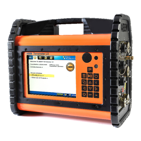
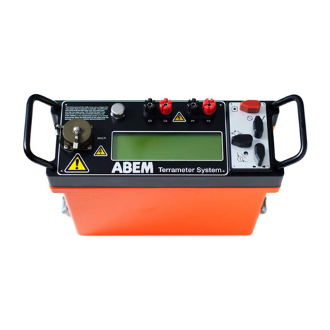
abem WalkTEM 2 User manual

CONTENTS
1. WALKTEM 2 RELEASE NOTES (WUI version 1.3.7.10) ............................................................................................... 2
2. CENTRE LOOP LAYOUT (TL-1K6, 40x 40m Transmitter Loop) ................................................................................... 3
A. Lay out the TL-1k6 transmitter loop first:............................................................................................................. 3
B. Lay out RC-5 receiver coil next: ............................................................................................................................ 3
C. Lay out RC-200 receiver loop: .............................................................................................................................. 3
D. Connect TX loop and RX coils to WalkTEM TX & RX units: ................................................................................... 4
E. Connect the WalkTEM TX & RX units together:.................................................................................................... 5
F. Connect external power to the TX (and RX if required):....................................................................................... 5
3. DAMPING RESISTOR DECISIONS ............................................................................................................................... 6
4. CENTRE LOOP LAYOUT (TL-400, 20X20m Transmitter Loop).................................................................................... 8
5. CENTRE LOOP LAYOUT (TL-10k HP6, 100x100m Transmitter Loop)......................................................................... 9
6. CENTRE LOOP LAYOUT (TL-40k HP6, 200x200m Transmitter Loop)......................................................................... 9
7. TX-60 LAYOUT, CONNECTIONS AND OPERATION ................................................................................................... 10
8. USER INTERFACE AND MEASUREMENT CONFIGURATION...................................................................................... 12
9. MEASUREMENTS .................................................................................................................................................... 15
10. FILE MANAGEMENT & INVERSION.......................................................................................................................... 15
11. WALKTEM 2 LAY-OUT DIMENSIONS ....................................................................................................................... 18

P a g e | 2
ABEM WALKTEM 2 ABRIGDED USER MANUAL
1. ABEM WALKTEM 2 RELEASE NOTES (WUI version 1.3.7.10)
The final stages of development for the WalkTEM 2 instrument have been impacted by the Covid-19 pandemic.
As a result the decision has been made to release the product with some limitations on functionality, and
reduced support literature, but to then release a series of firmware and documentation updates to improve the
operation and customer experience in the coming months. The instrument, as it stands, is a high-specification,
fully functioning TEM device which we believe you will be happy with and we are excited about some of the
improvements to be made in the upcoming releases; we hope you will be too. If you encounter any issues please
do not hesitate to contact your local Guideline Geo representative or email support@guidelinegeo.com
Known Issues and Limitations:
A. Battery Status: Depending upon the design of the internal batteries, you may only see 92% charge on the
fuel gauge if the batteries have been charged internally (as opposed to using the external cradle).
B. Self-discharge of Batteries: The instrument has some circuitry which is only dormant on power-down rather
than completely disconnected. As such, it is advisable to remove the batteries if the instrument is not is use
for a long period of time.
C. Rogowski Coil Tests: At present, the damping resistor selection is a manual process only; after running the
test the user can plot the results and make a choice based on the shape of the decays. This is an
improvement over the previous WalkTEM but it is hoped that the instrument will be able to suggest the best
resistor in the future. We are currently training the AI algorithm to do this.
D. HighMoment_Noise_10_90ms Script: If a sounding has been made with this script, do not restart the
measurement within 3 seconds of the completion notification appearing on the screen. The TX unit will not
reinitiate within that short time frame.
A NOTE ON CALIBRATION
Again, due to the Covid-19 situation, it has not been possible to access the regular Guideline Geo calibration site.
The initial release of WalkTEM 2 instruments have undergone a laboratory-based calibration and basic
verification. Contact support@guidelinegeo.com for more information.
Version: 1.50
Date: April 2021

P a g e | 3
ABEM WALKTEM 2 ABRIGDED USER MANUAL
2. CENTRE LOOP LAYOUT (TL-1K6, 40x 40m Transmitter Loop)
A. Lay out the TL-1k6 transmitter loop first:
−to ensure current flow and measurements are all positive, we
lay everything in a clockwise order;
−a compass, optical square or tapes can be used to help make
the loop square - it does not need to be a perfect square
to still perform acceptably;
−leave the loose end of the loop near the TX unit and
walk around with cable drum;
−use the black markers on the
loop as a guide for the
corner positions:
B. Lay out RC-5 receiver coil next:
−this is easiest to locate centrally;
−either use people on the corners of the transmitter loop to
align someone in the middle OR (easier) walk from the middle
of one side, toward the middle of the other side, measuring
the distance as you walk.
−the RC-5 coil is running
clockwise when the black
connector is on the top (right);
−ensure that the RC lead-in
cable is not coiled and
crosses the transmitter
loop at 90° (or as close as possible).
C. Lay out RC-200 receiver loop:
−use the RC-5 as a guide for centring
and aligning the RC-200;
−the RC-200 loop also has
corner markers on the cable;
−at the corner of the RC-200 there is a
connector box with a diagram on it to show
which is the correct direction for laying
it out (see image, right);
−ensure that the RC-200 cable
is not coiled, runs parallel to
the RC-5 cable separated by
~2m, and crosses the transmitter
loop at 90° (or as close as possible).
Connector box
at corner of RC-200
loop

P a g e | 4
ABEM WALKTEM 2 ABRIGDED USER MANUAL
D. Connect TX loop and RX coils to WalkTEM 2 TX & RX units:
−the RC-5 / RC-200 connect to Inputs A and B, on the RX unit; it is good practice to put the RC-5 into Input
A and the RC-200 into Input B;
−a 3m lead-in cable connects the TL-1k6 to the TX unit; the black connector attaches to the cable drum,
and the red connector attaches to the loose end of the loop. It is only possible to connect it one way
round as the loop end of the 3m lead-in cable has one male and one female connector;
−see Section 3 “Damping Resistor Decisions” for instructions on manually choosing a damping resistor if
you intend to use an external resistor rather than one from the internal array.

P a g e | 5
ABEM WALKTEM 2 ABRIGDED USER MANUAL
E. Connect the WalkTEM 2 TX & RX units together:
-use the 1.5m TX sync cable to connect the WalkTEM 2 RX and TX units together. Although it is advised to
connect this cable before powering up the instruments, the units will sync at any time the connection is
made.
F. Connect external power to the TX (and RX if required):
-the minimum requirement for the TX-8 / TX-20 unit is a single 12V battery;
-an additional 12V battery can be connected in series for 24V;
-adding a further 6V battery in series will provide 30V and
allow the TX to reach maximum current.
NOTE: when setting up to use 24V or 30V, ensure correct connection
polarities,otherwise there is a risk of damage to the instrument and
harm to the operator. If in doubt consult someone with relevant
experience.
1.5m TX sync cable
30V
24V

P a g e | 6
ABEM WALKTEM 2 ABRIGDED USER MANUAL
3. DAMPING RESISTOR DECISIONS
When we rapidly shut off the current in a transmitter loop, a ‘ringing’ effect is created – an unwanted
oscillating and decaying current. We use a damping resistor in parallel with the transmitter loop to minimise
this effect and the size of the resistor will depend upon the loop properties and the ground over which it lies.
In the original WalkTEM all damping resistors were mounted externally and the choice was entirely down to
the operator and their experience of how a ‘good’ sounding should look. With the WalkTEM 2, there are a
range of damping resistors installed inside the TX unit, which it is possible to test and analyze in order to
determine the best possible resistance value for any given loop or survey area. The analyzer will also run a
test on the loop without any of the internal resistors connected thus it would still be possible to mount a
custom resistor externally and review its suitability; mounting of an external resistor is covered in Part D of
this section. The analysis process would be as follows:
A. Set-up the instrument with a transmitter loop:
-connect the RX and TX units plus, as a minimum, the
transmitter loop and power on;
-you need an active project and to select a measurement
script before the “Analyze” button will activate.
B. Select “Analyze”, press ENT, and follow the screen prompt:
-take out the Rogowski coil (below right) and open it, if necessary, by pulling the free end of the loop (A)
from the blue connector;
-wrap the loop around one of the transmitter coil leads, using the arrow on the blue connector to orient
in the correct direction with respect to the direction of current flow in the transmitter loop;
-plug the other end of the Rogowski coil into Input B on the left side of the RX unit (you may need to
unplug the RC-200 from Input B);
-press “OK”.
Sync
cable
Power
RX
TX
TX Loop
TX
A

P a g e | 7
ABEM WALKTEM 2 ABRIGDED USER MANUAL
C. Once the test measurements have finished, plot the data and choose the best resistor:
-hit “Plot” and a new window will open showing the
resulting curves;
-the time axis is in real units but the decay curves
are normalized within the current zoom level to
arbitrary units;
-the arrow keys allow panning and zooming with the
“Shift” key ( ) toggling between the two functions;
-keys 1 to 6 will switch on/off the individual decay
curves;
-pressing numeric key “0” cycles through adjacent
decay curves, showing two at a time, for easier
comparison;
-decreasing the line width can help visualize the
curves better;
-decreasing the line width can help visualize the curves better;
-if the curve is inverted, reverse the Rogowski coil or place it on the other tail of the TX;
-the aim is to pick the decay curve with the steepest drop-off which also returns to zero quickly and
without too much further oscillation –typically larger loops and more conductive ground require bigger
damping resistors;
-once the best resistance value has been identified, press “Esc”to close the Rogowski plotter and select
the relevant resistor from the drop down menu.
D. Using an external damping resistor:
-if a custom resistance value is desired it is possible to
mount one externally in parallel with the transmitter
loop;
-use a good quality “power resistor”that can withstand
the load put on it by the transmitter;
-the resistor should be attached to the instrument end
of the 3m TX lead-in cable (right) –although this image
depicts the connection on a WalkTEM 1, the
arrangement would look the same on a WalkTEM 2 TX
unit;
-connection of the Rogowski coil should be on the TX
lead-in cable and not around the resistor leads;
-the results of the Rogowski test for this external resistor
will be the decay labelled “none”as none of the internal
resistors are in use on that measurement.
NOTE: When a Rogowski coil test is run with an external resistor attached, the
decays shown for the internal resistors will be affected by the external resistor’s
presence; those decays will show the combined effect of the external resistor and the internal resistor.
E. Using an external damping resistor:
-the results of the tests are written out to a time-stamped folder and stored within the file structure of
the regular measurement data;
-the results are in a simple text format and therefore can be imported into other software packages for
plotting and / or further analysis.
TX 3m
Lead-in
Cable

P a g e | 8
ABEM WALKTEM 2 ABRIGDED USER MANUAL
4. CENTRE LOOP LAYOUT (TL-400, 20X20m Transmitter Loop)
A. Similar layout to using the TL-1k6:
-pull out the TL-400 transmitter loop first, leaving
the free end of the loop next to the instrument
and walking around with the cable drum.
-The loop has corner markers every 20m;
-next lay the RC-5 at the centre of the TL-400;
-the RC-200 cannot be used with the 20x20m
loop as there is not enough space between the
two loops and interference will occur;
-now connect the RC-5 to the instrument,
typically via Input A;
-the TL-400 is connected to the
instrument via the 3m lead-in
cable again but also through a
1.5 Ohm “choke”resistor on
one side of the cable (in
series with the loop, not in
parallel). This counteracts
the low resistance
associated with this very short
transmitter loop and limits the
maximum current to safe levels;
-see Section 3 “Damping Resistor Decisions”
for instructions on manually choosing a
damping resistor.
B. Powering the TX:
-a 20x20m transmitter loop should only be
powered with 12V (i.e. 1 battery).
CHARGING THE INTERNAL BATTERIES
The WalkTEM 2 RX has two internal batteries and these can be charged in the instrument
or the separate charging cradle.
The TX-60 battery is non-removeable and can only be charged using the Office Power Supply; the
TX-60 must be switched on to charge (but it does not need to be attached to the WalkTEM 2 RX).
The TX-8 and TX-20 do not have internal batteries.

P a g e | 9
ABEM WALKTEM 2 ABRIGDED USER MANUAL
5. CENTRE LOOP LAYOUT (TL-10k HP6, 100x100m Transmitter Loop)
A. Similar layout to using the TL-1k6:
-pull out the TL-10k transmitter loop first,
this loop is split across two reels;
-leave the loose end of the loop by the
instrument and walk around with the
cable drums;
-next lay out the RC-5, if used (not necessary
if primary focus is deeper responses);
-lay out the RC-200;
-RC-5 / RC-200 are now connected to the
instrument via 62m extension leads
(total lead-in distance for each
coil is now 95m);
-the TL-10k is connected to
the TX unit via the 3m
lead-in cable;
-see Section 3 “Damping
Resistor Decisions” for instructions on manually choosing a damping
resistor.
B. Powering the TX:
-a 100m transmitter loop would normally be powered with a minimum of 24V (i.e. 2 batteries).
6. CENTRE LOOP LAYOUT (TL-40k HP6, 200x200m Transmitter Loop)
A. Start by laying out transmitter Loop:
-each side is one complete reel of cable;
-leave the loose end of the loop by the
instrument and walk around with the
cable drums;
-no RC-5 because the 200m loop has a
long switch-off time, so shallow responses
are undetectable;
-the RC-200 is now connected to
the instrument via two 62m
extension leads;
-the TL-40k is connected
to the instrument via
the 3m lead-in cable
again;
-see Section 3 “Damping
Resistor Decisions” for
instructions on manually
choosing a damping resistor.
B. Powering the TX:
-a 200m transmitter loop should be powered with a minimum of 24V (i.e. 2 batteries).

P a g e | 10
ABEM WALKTEM 2 ABRIGDED USER MANUAL
7. TX-60 LAYOUT, CONNECTIONS AND OPERATION
A. The TX-60 is only designed for use with 100m and 200m high power loops (TL-10k HP6 & TL-40k HP6,
the TX-8/TX-20 can operate with old-style non-HP6 loops)
B. Layout of the loops is the same as described in previous pages, except for:
- the RC-5 is unnecessary because the TX-60 has no low-moment phase;
- Transmitter Loops are connected with a different lead-in cable, compatible with the HP6 / TX-60
connectors.
C. The TX-60 should be powered by at least 4 batteries:
One for powering the control electronics & cooling fans, and at least 3 for supplying the current
generator. Only using two batteries for the current generator is no different from running the
WalkTEM 2 on 24V without the TX-60. More batteries will increase the
voltage (to a maximum of 250V) and create
a higher transmitter current.
D. For short measurement campaigns the
TX-60 control electronics and fans can
use the internal battery but an
external power source is preferred.
The internal battery cannot
power the transmitter circuit.
TX-60 END PANELS

P a g e | 11
ABEM WALKTEM 2 ABRIGDED USER MANUAL
WALKTEM vs TX-60 TRANSMITTER LOOP LEAD-IN CABLES
WALKTEM TX-60 STATUS LIGHTS
CONNECT ALL BATTERIES IN SERIES BEFORE
CONNECTING THE CABLE PLUG TO THE TX-60
It is critical to observe the correct polarities when
connecting batteries in series. A wrong connection can
result in equipment damage as well as personal injury.
Only attempt connection if you understand electrical
circuits, otherwise seek qualified assistance.
The standard lead-in wire for use with the original WalkTEM used “banana plug” connectors; the WalkTEM 2 and the TX-
60 use a heavier gauge wire, split-spade connectors and screw terminals:
Original
WalkTEM WalkTEM 2 & TX-60
Lead-in Lead-in Cable
Cable

P a g e | 12
ABEM WALKTEM 2 ABRIGDED USER MANUAL
8. USER INTERFACE AND MEASUREMENT CONFIGURATION
KEYPAD FUNCTIONS
Tab for setting up
measurement
parameters.
Tab for initiating
and monitoring
data collection.
Tab for file
management and
inversion.
Tab for instrument
settings and error
logging.
Select existing project to
add in additional stations
or create a new one.
Choose your preferred
measurement script with this
drop-down and how many
repetitions on the right; total
time is shown on the right and
details of the script are
summarised below.
Notifies of issues recorded on
the Administration tab.
Select the loop you will use for
measurement. The choice is
limited on an RX Standard.
Shows number of satellites in
use for positioning.
Select one of the internal
damping resistors from the
drop-down or choose to use a
custom external resistor.
Selecting “Analyze”provides
instructions on performing a
Rogowski Coil test to assess
which damping resistor to use.
This feature is included on the
RX Advanced and an optional
extra on the RX Standard.
“Plot”will show the results of
the Rogowski Coil tests so you
can choose the most suitable
damping resistor.
Select which coils and input you
will use; RC-5 on A is only
option on an RX Standard.
“Ext Power” shows if the office power supply is
attached or the voltage of externally connected 12V
batteries (when connected) –any external battery will
take over from the “Bat 1” internal battery.
“TX-8 / TX-20 / TX-60” indicates
voltage on the TX unit (when
attached).
“Bat 1 / Bat 2” shows the voltage of the internal battery
pair. These run the computer, screen and receiver if there is
no external power source. To do a ‘hot swap’, keep one
battery in place whilst changing the other.
Set-up a schedule for repeated
measurements.
Yellow shows TX is initialising,
green means everything is okay
with the TX / RX and ready to
measure. During measurement,
icons change to show system is
active.

P a g e | 13
ABEM WALKTEM 2 ABRIGDED USER MANUAL
A. The first step is to navigate to the
“Administration”tab (PGUp or PGDn)
and choose the correct frequency of
electricity transmission for the country
or region you are surveying within.
This ensures that only the measurement
scripts suitable for use in that region are
offered on the configuration tab.
A summary, listed by country, can be found here
–other resources are available:
https://en.wikipedia.org/wiki/Mains_electricity_
by_country#Table_of_mains_voltages_and_freq
uencies
Accessed: 5th October 2020
B. Navigate back to the
“Configuration” tab and
either use the currently
active project, a previous
project to add additional
stations or select “New
Project”.
Projects are automatically
numbered sequentially.
C. After creating the
project, select the
correct Transmitter
Loop. Remember to
undertake the Rogowski
Coil test (see Section 3)
to determine the best
damping resistor.

P a g e | 14
ABEM WALKTEM 2 ABRIGDED USER MANUAL
D. Next add in which receiver coils are being used
on each input channel.
For a 20x20m loop, only use the RC-5.
For a 40x40m or 100x100m transmitter loop,
the RC-5 & RC-200 can both be used.
For a 200x200m loop, only use the RC-200.
Offsets can be configured here as well as the
orientation of the RX coil. A “Z”component
measurement would be from a regular,
horizontally laid, receiver. “X”and “Y”are
when the loop is mounted vertically with
respect to the transmitter loop. “X”would
normally be with the RC antenna aligned up
the centre of the transmitter loop; “Y”would
be with it aligned across the centre of the
transmitter loop.
E. Now that the hardware is configured, the
final step is to choose a suitable script. A
table is provided below to assist with the
choice.
The “Number of Cycles”box is how many
times the script (which in itself contains
hundreds of stacked measurements –see
table) will be repeated. Increasing this will
increase the signal to noise ratio and help
with the deeper signals. But it lengthens the
survey time; 3-5 is acceptable under normal
conditions.
On the right-hand side, an indication of how
long the measurement will take is given.

P a g e | 15
ABEM WALKTEM 2 ABRIGDED USER MANUAL
9. MEASUREMENTS
10. FILE MANAGEMENT & INVERSION
A. All that is required on this page is to
press “Start”. This will initiate the cycle
of noise, low moment and high
moment measurements.
A progress bar will indicate how far
into the measurement process you are
and an estimation of time remaining.
The instrument has both audio (for
which the supplied Bluetooth speaker
is required) and visual notifications
that the measurement is complete.
B. Use the TAB button to select the first tab
above the data plot on the right-hand side
of the screen. The left and right arrow will
now switch between the different real-time
measurement views.
•ChA-All and ChB-All will redraw the curve each
time a new High Moment, Low Moment or
Noise measurement is made on Channel A and
B, respectively.
•In the example here, only the RC-5 is being used
and thus ChB feeds are not available to view.
•The remaining tabs show only one of the
measurement phases (High, Low or Noise) for
each channel. These refresh the next time one
of these measurement phases are completed
A. Use the Down Arrow to select a
project.
The Right Arrow will expand the ‘tree’
to show soundings (Stations) measured
within that project.
The Menu button ( ) will give a series
of file management options for the
Project or the Station depending upon
which is highlighted.
Some of these actions have shortcut
keys listed on the right of the screen.
To use the “Export”options, a USB
drive will need to be attached to the
instrument.
A

P a g e | 16
ABEM WALKTEM 2 ABRIGDED USER MANUAL
B. To review soundings, select “Plot Data”from
the menu or shortcut to it by pressing “Shift+7”.
This will initiate the ABEM WalkTEM
Visualization Tool; a title screen will show whilst
it loads.
When the viewer starts, by default, it will show
the stacked decay curves (dB/dt) for all available
moments and receiver coils. The data from high
and low current, RC-5 and RC-200 are all
presented as different colors.
To view raw (unstacked) curves, use the space
button ( ) to toggle between the two views;
the raw view will also reveal the noise
measurements. It is also possible to switch
between the stacked and raw views by clicking
on the circular selection buttons, if a mouse is
connected to the instrument.
To view apparent resistivity curves, use the
“Ctrl” button to toggle between the two views.
It is also possible to switch between the decay
and apparent resistivity views by clicking on the
circular selection buttons, if a mouse is
connected to the instrument.
Number keys 1 –6, will toggle on/off the
individual data sets. This can also be achieved
by clicking on the named buttons in the top-left
of the screen if a mouse is attached.
The display will automatically fit to the
data extents but it is possible to zoom in/out
using the “PgUp”/“PgDn” buttons. The arrow
keys will pan the screen. If a mouse is attached
the scroll wheel will zoom in/out. Using the
scroll wheel with the mouse pointer in the
centre of the plot zooms both axes together.
Using the scroll wheel with the mouse pointer
over one of the axes will adjust only that scale.
Moving the mouse whilst holding the right
mouse key will pan. To reset to default zoom,
press “0” or click the “RESCALE” button with a
mouse.
Screenshots can be taken by pressing “Shift+0”
or clicking on the “SCREENSHOT” button with a
mouse. These images will be saved into the
project folder and exported with the data.
To exit the ABEM WalkTEM Visualization Tool
press escape or click the “x” in the top-right of
the screen.

P a g e | 17
ABEM WALKTEM 2 ABRIGDED USER MANUAL
C. With a station highlighted, either select
“Model Data”from the menu or shortcut
to it by pressing “Shift+4”.
The SPIA TEM software will start (this can
take some time).
Use PgUp/PgDn to switch between the
inversion tab and the data view tab
where options to view individual
channels and raw or stacked curves are
available.
When ready to carry out an inversion,
ensure that the small black arrow is at
the right-hand end of “Run Inversion”
(this may require a single press on the
down arrow on the WalkTEM 2 front
panel) and press “Ent”on the keypad.
The inversion software will automatically
discard poor quality readings and
complete the inversion provided there
are sufficient good data points available.
Data points that will be carried forward
for the inversion are always coloured,
whilst those which have been
automatically discarded will be greyed
out.
After the inversion has been completed
(approximately 1-2 minutes), a smooth-
layered model will be displayed with a
residual value giving an indication of the
model’s reliability.
To exit SPIA TEM and return to the data
collection software, press “ESC”.
The modelled data will be saved in the
regular project folder and exported along
with the sounding data. Once the project
is opened in the desktop version of
Aarhus SPIA TEM, the instrument
inversion will be there and available for
further processing or just as a
comparison with a new set of inversions.

P a g e | 18
ABEM WALKTEM 2 ABRIGDED USER MANUAL
11. WALKTEM 2 LAY-OUT DIMENSIONS
Tapes or measuring wheels can be used to layout accurate loops if so desired, using the following
measurements:

P a g e | 19
ABEM WALKTEM 2 ABRIGDED USER MANUAL
Table of contents
Other abem Measuring Instrument manuals