CellScale MechanoCulture TM User manual

MechanoCulture TM
Mechanical Stimulation System
User Manual
version 1.1

MechanoCulture TM User Manual
CellScale is an industry leader in biomaterial and mechanobiology
test systems.
Our mechanical test systems are specifically designed for characterizing the
material properties of biomaterials. With integrated features such as image
capture and analysis, media chambers, and a range of gripping mechanisms, our
biaxial and micro-scale compression test systems are capable of generating high
quality test data from day one.
Our mechanobiology technologies help advance research by providing insights
into the response of cells to mechanical stimulation. CellScale has systems
optimized for high-throughput, real-time imaging, and 3D scaffold use. In addition
to our standard products, CellScale can also develop a custom solution for your
application.
Our products are used by researchers around the globe to study everything from
tissue strength and stiffness to cellular response. Please visit our website for more
information and a list of publications. Also, please contact us to find out how our
test systems can help you.
© 2022 CellScale. All rights reserved. This material may not be reproduced,
displayed, modified or distributed without the express prior written permission of
the copyright holder. For permission, contact CellScale Biomaterials Testing at
Sales and Support
CellScale Biomaterials Testing
11 –564 Weber St. N.
Waterloo, Ontario, Canada N2L 5C6
Phone: 519.342.6870

MechanoCulture TM User Manual
Table of Contents
1. General Information................................................................................................................. 1
Environmental and Electrical Specifications................................................................................ 1
System Assembly......................................................................................................................... 1
Connections to Supply................................................................................................................. 1
Safety Warnings........................................................................................................................... 1
Manual Operating Controls.......................................................................................................... 1
General Maintenance................................................................................................................... 1
Approvals and Certification.......................................................................................................... 1
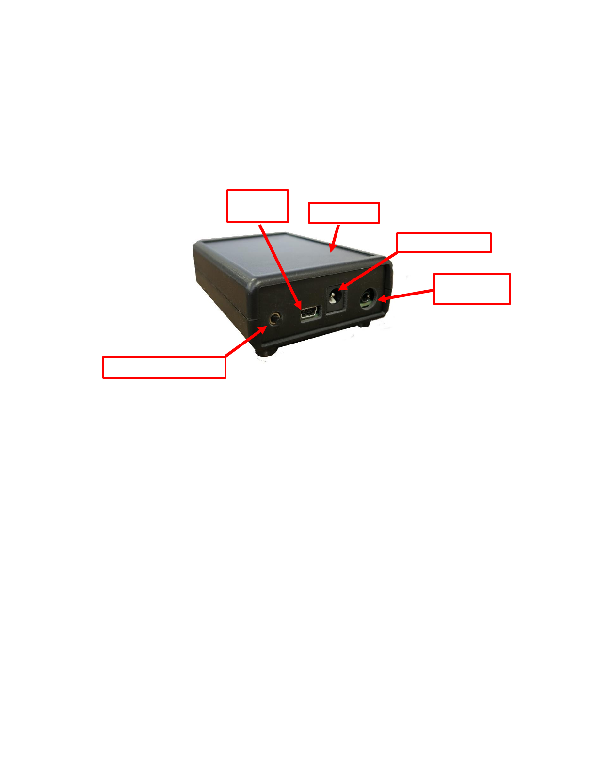
2. Components Overview............................................................................................................. 2
3. Testing Terminology ................................................................................................................ 3
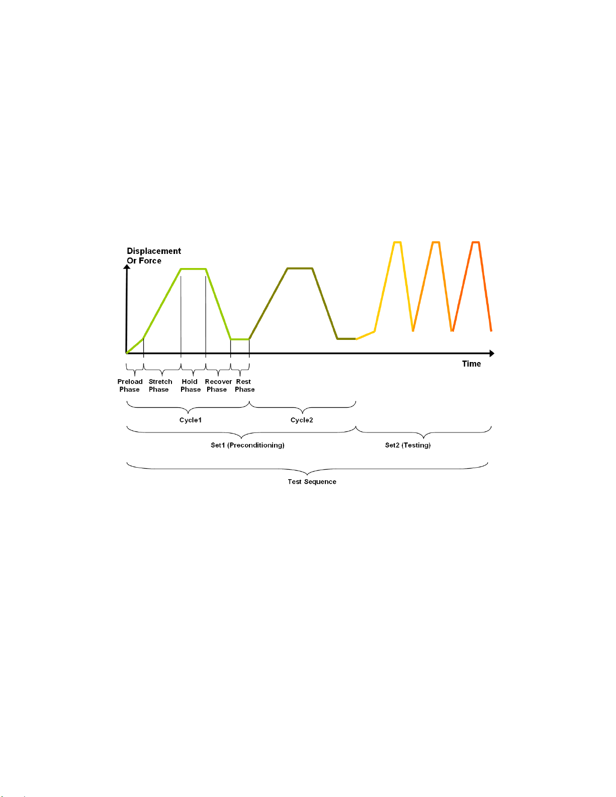
Multiphase Test Cycles................................................................................................................ 3
Phases, Cycles, and Test Sequences......................................................................................... 3
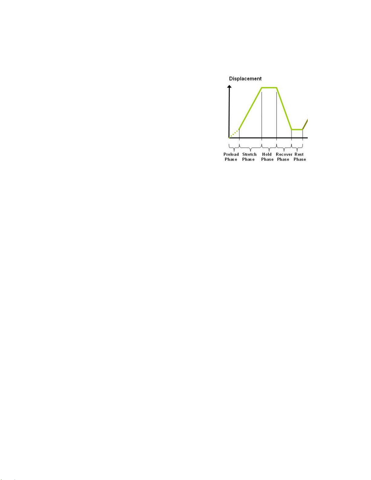
Test Phases: The Smallest Unit of Testing.................................................................................. 4
Control Functions......................................................................................................................... 4
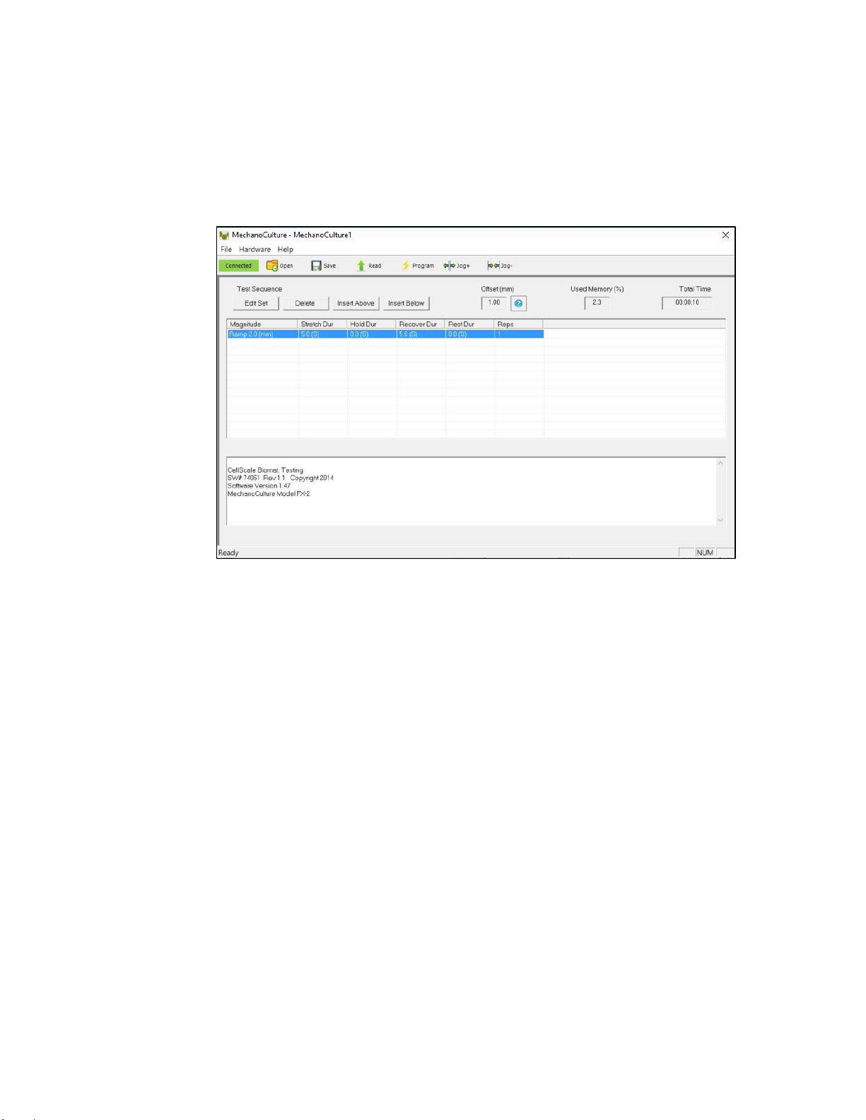
4. Software Overview................................................................................................................... 5
Step 1: Initiate a Test Sequence.................................................................................................. 5
Step 2: Modify Testing Parameters (optional) ............................................................................. 6
Step 3: Program a Device with the Specified Test Sequence..................................................... 6
Well Plate Pre-Stretch, Device Reset Movement, and Offset Distance ...................................... 7
Offset and Jog Functions............................................................................................................. 8
5. Designing Test Sequences...................................................................................................... 9
Example 1: Continuous Cycling for Fixed Duration and then Stop.............................................. 9
Example 2: Pre-stretch a Single Time, Then Cycle for a Fixed Duration, and Then Stop ........ 11
Example 3: Intermittent Stretching............................................................................................. 13
6. Setting Up & Running a Test ................................................................................................. 14
Overview.................................................................................................................................... 14
Attach the Sterilized Membrane to the Test Device................................................................... 14
Plug in Control Box Power. Connect Control Box and Test System ........................................ 14
Program the Device (if needed)................................................................................................. 14
Reset the system (hold down the button for 5 seconds)............................................................ 14
Add Cell Media and Cells. Culture to Develop Adhesion ......................................................... 14
Execute Test.............................................................................................................................. 14
7. Advanced Parameters ........................................................................................................... 15
8. Appendix A: Updating the Firmware...................................................................................... 16
9. Appendix B: Software Installation.......................................................................................... 17

MechanoCulture TM User Manual
1
1.General Information
The MechanoCulture TM is a precision instrument specifically designed for deforming flexible
membranes in a sterile fluid environment. The device has an onboard actuator and a detached
control board to enable it to run independently of a computer in an environment-controlled
incubator.
Environmental and Electrical Specifications
Electrical Input
24VDC
Current Rating
1.2 Amp
Environmental
Conditions
Maximum Operating Temperature
40ºC
0% - 100% Relative Humidity
Installation Category
Category II
Pollution Degree
Degree 2
Data Connections
mini USB for programming
3.5mm TRRS Connection Cable to
run actuator
System Assembly
The unit requires some initial assembly as well as some assembly/disassembly required between
uses. See Appendix C for assembly instructions.
Connections to Supply
Connect power cord into properly grounded 100-240VAC power source to ensure safe operation.
The mains supply voltage fluctuations should not exceed 10% of the nominal supply voltage.
Safety Warnings
This equipment must be used in accordance with the procedures outlined in this manual to
prevent injury and/or damage.
The unit should not be operated without the motor housing in place.
Manual Operating Controls
There is one push-button switch on the front of the control unit. A single push will start and stop
the test sequence. A push and hold for 5 seconds will advance the actuator and reset the test
sequence to the beginning
General Maintenance
The equipment does not require maintenance other than cleaning. Please see the components
overview section for cleaning and sterilization details.
Approvals and Certification
This product conforms to EN61010-1:2001 and EN61326-1.

MechanoCulture TM User Manual
2
2.Components Overview
Power Input Port
3.5mm TRRS
Cable Jack
Start/Stop/Reset Button
Control Box
Mini USB
Port

MechanoCulture TM User Manual
3
3.Testing Terminology
Multiphase Test Cycles
In order to properly mechanically stimulate/signal cells, it is often necessary to apply more than
one load magnitude or frequency during the course of the test.
Phases, Cycles, and Test Sequences
As the following diagram demonstrates, each application and release of the well plate is called a
test cycle. The same test cycle can be repeated multiple times to achieve a certain goal. This is
called a test set. Finally, a test sequence is made up of multiple test sets.
The above example describes the following:
•The entire diagram presents a full test sequence.
•Within that sequence, there are two test sets.
•Within the first set, two identical test cycles are implemented.
•Finally, the second set is made up of three cycles.

MechanoCulture TM User Manual
4
Test Phases: The Smallest Unit of Testing
The test phase is the smallest unit of the test specification. There are four phases within a cycle.
Each phase serves a specific purpose:
Stretching - During the stretch phase, a
deformation is applied to the specimen.
Holding - The deformation can be held for a
given duration.
Recovering - The recovery phase is the time
during which the deformation imposed during the
stretching phase is removed.
Resting - Finally, the rest phase is the time
between the end of one cycle and the beginning
of the next.
Control Functions
The MechanoCulture makes it possible to stimulate specimens under two control functions:
The ramp function applies the displacement at a constant velocity.
The sine function applies the displacement according to a sinusoid with the desired
displacement magnitude and duration.

MechanoCulture TM User Manual
5
4.Software Overview
The MechanoCulture software is used to program the device with the phases, cycles, and sets
that comprise the test sequence. The screen layout is shown below:
Test
Parameters
Message
Window
Step 1: Initiate a Test Sequence
Test sequences can be initiated in 3 different ways:
1. A predefined test sequence can be opened from a MechanoCulture Protocol File (*.tmt).
From the File menu, select Open, or press the Open button on the toolbar.
2. A currently programmed test sequence on a device can be read. From the Hardware
menu, select Read, or press the Read button on the toolbar. To read a MechanoCulture
device, it must be connected to the computer’s USB port with a USB cable and it must
be powered on.
3. A new test sequence can be created by pressing the Insert Above or Insert Below
buttons to add sets to the test sequence. Each set will have its own row in the table and
sets will be executed sequentially. A test sequence can have a maximum of 8 sets.

MechanoCulture TM User Manual
6
Step 2: Modify Testing Parameters (optional)
You can select and modify parameter sets by clicking
on their row in the Test Parameter Specification table
and then pressing the Edit Set button (or by double
clicking on their row). When you do so, the Set
Parameter Editor Dialog will appear.
Note that displacements are specified in mm and are
relative to the current position. Time units are applied to
the entire set but different sets can have different time
units.
The Do Not Stretch and Do Not Recover check boxes
allow for the stretch or recover phases to be omitted
during a testing cycle. This makes the creation of test
sequences that include preloading possible.
Step 3: Program a Device with the Specified Test Sequence
From the Hardware menu, select Program, or press the Program button on the toolbar. To
program a MechanoCulture device, it must be connected to the computer’s USB port with a USB
cable and it must be powered on.
MechanoCulture Tip: Saving Test Sequence Protocols
Once you have developed a test sequence, you can save it as a MechanoCulture
Protocol file for future use. Select Save from the file menu, or press the Save button on
the toolbar. You can then open this test sequence the next time you initiate a test
sequence.

MechanoCulture TM User Manual
7
Well Plate Pre-Stretch, Device Reset Movement, and Offset
Distance
On power-up, the system’s actuator will go through a series of moves in order to achieve the
correct starting position. These moves involve fully extending the actuator and then retracting to
the correct load position. This series of moves is necessary to ensure that the actuator is in the
correct global position at the start of the test as all the movements in the test protocol will be
relative to this position.
During the reset movements, the distance that the actuator retracts back from its fully extended
position is called the offset.
The offset value can be changed by selecting “Hardware”, then “Advanced”, and then “Settings”
from the software menu. Within the dialogue, the offset parameter can be specified and
programmed to the device controller. This offset will be applied globally to all test protocols once
the “Program” button is clicked.
As a reminder, the offset will be reapplied on every power up of the controller and every time that
the controller button is pressed and held for 5 seconds to trigger a reset. The only exception to
this is the situation where the device is paused while running a protocol (by pressing but not
holding the button). In this case the actuator will not reset on power up so that the protocol can be
continued by a second button press.
If it is desired to unplug the controller after the cells have been seeded but before the protocol
has been started, it is recommended to take steps to ensure that the reset protocol does not
disturb the cells. This can be accomplished by unplugging the actuator cable (TRRS, not the USB
cable) from the control box during power up.

MechanoCulture TM User Manual
8
Offset and Jog Functions
The offset function for the MechanoCulture TM is programmable by the user and how to do this
is shown later in the manual.
The jog buttons let you extend and retract the actuator outside of executing a test. When the
actuator is jogged, the offset value will automatically update and display the current position of
the moving pins.

MechanoCulture TM User Manual
9
5.Designing Test Sequences
The MechanoCulture software allows for complex test sequences to be generated. The
examples in this section illustrate how to generate different types of test protocols.
Example 1: Continuous Cycling for Fixed Duration and then Stop
Objective: Create a test sequence that cycles at 0.5 Hz with 2.6mm of stretch for 24 hours and
then stops.
Press Insert Above to create a Set. Then double click
on that row to modify it.
0.5 Hz is a period of 2 s. In this example, the period is
divided into 1 s of stretch and 1 s of recovery with no
hold or rest.
To achieve a 24 hr test duration requires 43200
cycles. (24 hr x 3600 s/hr / (2 s/cycle)).
MechanoCulture Tip: Terminating a test
The MechanoCulture software will loop through the test sequence indefinitely. To prevent
the sequence from repeating itself, add a test set to the end of the sequence that includes
a lengthy rest duration but no stretch or recovery. For example, 21 days of rest could be
added to the end of the test sequence (see below for full test sequence).

MechanoCulture TM User Manual
10
The resulting actuator motion versus time graph for the first 30 seconds:
0
0.5
1
1.5
2
2.5
3
0 5 10 15 20 25 30
Displacement (mm)
Time (S)

MechanoCulture TM User Manual
11
Example 2: Pre-stretch a Single Time, Then Cycle for a Fixed
Duration, and Then Stop
Objective: Create a test sequence that starts with a 0.5 mm pre-stretch in 1 minute followed by
100 cycles of an additional 2 mm stretch (5-minute stretch, 1-minute hold and 4-minute recover).
1. Press Insert Above to create a Set. Then
double click on that row to modify it.
Check the Do Not Recover box to omit the
recovery phase.
2. Press Insert Below to create a second set.
Modify this set as follows: Note that the 5 mm
stretch magnitude is relative to the current
position of 1 mm from the previous set (the
total global stretch will be 6 mm).
3. To terminate the test at the end of 24 hours, insert a lengthy rest set (21 days in this
example) to the end of the sequence. If this set is not included, the protocol will
automatically restart at the end of the first set (see the MechanoCulture tip in Example 1).
The test sequence is shown below:

MechanoCulture TM User Manual
12
The resulting actuator motion versus time graph for the first 30 minutes:
0
0.5
1
1.5
2
2.5
3
0 5 10 15 20 25 30
Displacement(mm)
Time (S)

MechanoCulture TM User Manual
13
Example 3: Intermittent Stretching
Objective: Create a test sequence that cycles at 1 Hz with 2mm of stretch for 10minutes followed
by 50minutes of rest. Repeat this pattern indefinitely.
1. Press Insert Above to create a Set. Then
double click on that row to modify it.
2. Press Insert Below to create a second set.
3. In this case, a test set with lengthy rest duration is not required since the test is designed
to repeat indefinitely. The test sequence is shown below:

MechanoCulture TM User Manual
14
6. Setting Up & Running a Test
Overview
As a user of the MechanoCulture, you are likely to develop your own test preparation and
execution protocol, but there are several elements that are common to most users. This manual
will not cover cleaning, disinfecting, sterilization, cell seeding, reagents, and a number of other
topics.
The protocol below should be used for running new test sequences. To re-run existing sequences
on new specimens, simply power-up the device, ensure the system has been reset, mount
specimens, and press the push button to execute the test.
Attach the Sterilized Membrane to the Test Device
See Appendix C for details and images.
Plug in Control Box Power. Connect Control Box and Test
System
Program the Device (if needed)
Connect the Device to the PC via USB
Launch the MechanoCulture Software
Generate a Test Sequence
Upload Test Sequence to Device
Reset the system (hold down the button for 5 seconds)
See comments in Section 4 for details on actuator reset, actuator offset, and well plate pre-
stretch.
Add Cell Media and Cells. Culture to Develop Adhesion
Be sure to set the well plate/carrier assembly on a clean surface so as not to smudge the exterior
of the membrane.
Execute Test
To execute the test sequence, simply press the push button once. To pause the sequence, press
the button again at any point. Once this has been accomplished, power can be removed and
then restored without affecting the test protocol. To restart the test, press the button once more.
To reset the device, press and hold the button for 5 seconds.

MechanoCulture TM User Manual
15
7. Advanced Parameters
Under the Hardware menu is an Advanced Settings menu containing several different values
which should be understood. The menu will appear as below:
Offset: Offset is a distance that controls the starting stretch magnitude of each test. For
example, if the offset is set to 1mm, when a stretch of 2mm is programmed it will stretch from
1mm to 3mm. When the system is reset by holding the push button down for 5 seconds it will
fully extend the actuator and retract it to the defined offset amount.
Actuator Travel Soft Limit: The actuator travel soft limit sets the maximum offset that can be
achieved via manual jogging (before a test) and maximum stretch magnitude in the protocol
editor.
A maximum soft limit of 43mm can be set to prevent the motor from bottoming out on full
retraction. If the offset is greater than the actuator travel soft limit, manual jogging will be
restricted to only the inward direction until the offset is the equal to or smaller than the soft limit.
Actuator Stroke: The TM actuator has 50mm of maximum travel.

MechanoCulture TM User Manual
16
8. Appendix A: Updating the Firmware
1. With the MechanoCulture connected to the PC and turned on, launch the firmware
update software located in the Windows start menu under MechanoCulture>Utilities.
2. Load the firmware file using the “Load Update File” button.
3. Click the “Connect” button.
4. Execute the update using the “Update” button.
Table of contents
Other CellScale Test Equipment manuals
Popular Test Equipment manuals by other brands

Greenlee Communications
Greenlee Communications Nautilus PE9 Series instruction manual

Sperry instruments
Sperry instruments PSl8031 operating instructions

Knick
Knick VariTrans P15000H1-KTA user manual

Wise
Wise TSW800TP Operation manual

Midtronics
Midtronics CPX-900 WiFi Quick reference guide

ENDEVCO
ENDEVCO 436 instruction manual