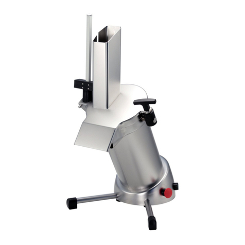
Celme CE L3 Specification sheet

INSTALLAZIONE - USO – MANUTENZIONE
INSTALLATION - USE - MAINTENANCE
INSTALLATION - UTILISATION - ENTRETIEN
INSTALACIÓN - USO – MANTENIMIENTO
IT TRITATUTTO DI VERDURE Pag. 2
GB VEGETABLES CUTTER Pag. 7
FR HACHOIR DE LEGUMES Pag. 12
SP PICADORA DE VERDURAS Pag. 17
PO PICADORA DE LEGUMES Pag. 22
CUTTER
CE L3
CE L5
CE L8 CE L5 2V
CE L8 2V
C.EL.ME S.r.l. – Viale Montenero, 1 Truccazzano (MI)
Tel. 029583157 - www.celme.com
IV Edizione – FEBBRAIO 2012

2
INDICE DEL CONTENUTO
Pag.
1 INFORMAZIONI SULLE SICUREZZE 3
1.1 Precauzioni generali 3
1.2 Sicurezze meccaniche 3
1.3 Sicurezze elettriche 3
2 CARATTERISTICHE TECNICHE 4
2.1 Dati tecnici 4
2.2 Stato di fornitura e smaltimenti imballaggi 4
3 INSTALLAZIONE 5
3.1 Collocazione della macchina 5
3.2 Allacciamento elettrico 5
3.3 Misure di sicurezza ed addestramento utente 5
4 USO DELL’APPARECCHIO 5
4.1 Comandi cutter 5
4.2 Inserimento merce e taglio 6
4.3 Regolazione lame 6
5 PULIZIA E MANUTENZIONE 6
5.1 Generalità e prodotti da usare per la pulizia 6
5.2 Rimozione del coperchio-pulisci pareti e lame 6
5.3 Rimozione vasca 6
5.4 Sostituzione del cavo d’alimentazione 6
5.5 Prolungata interruzione d’uso della macchina 6
5.6 Accessori a richiesta 6
6 ALLEGATI
Figure 27-28
Schema elettrico 29
DESIGN E CARATTERISTICHE TECNICHE POTRANNO ESSERE MODIFICATI ANCHE SENZA PREAVVISO.

3
1) INFORMAZIONI SULLE SICUREZZE
1.1 PRECAUZIONI GENERALI
Il cutter deve essere utilizzato da personale addestrato che deve conoscere le norme per l’uso e di
sicurezza contenute nel manuale.
Nel caso d’avvicendamento del personale provvedere all’addestramento.
Anche se la macchina è munita di vari sistemi di sicurezza, è necessario evitare di avvicinare le mani
alle lame taglienti.
E' importante prima di iniziare la pulizia di scollegare la macchina dalla rete d’alimentazione elettrica.
Controllare periodicamente lo stato dei cavi e delle parti elettriche.
Non usare gli apparecchi con prodotti surgelati.
Non eseguire personalmente riparazioni ma rivolgersi a personale specializzato.
1.2 SICUREZZE MECCANICHE
I Cutter di nostra costruzione descritti in questo manuale rispondono, per quanto riguarda le sicurezze
contro i rischi di natura meccanica, ai requisiti essenziali di sicurezza prescritti dalle direttiva macchine
2006/42/CEE. Per la conformità igienica alla direttiva 1935/2004/CEE.
1.3 SICUREZZE ELETTRICHE
I Cutter sono costruiti conformemente ai requisiti essenziali di sicurezza previsti dalla direttiva bassa
tensione 2006/95/CEE. Le sicurezze contro i rischi elettrici sono realizzate in conformità alle norme 60335-2-
64.
E' stato adottato un microinterruttore di sicurezza sul coperchio che interrompe il funzionamento della
macchina in caso d’apertura per permettere l’accesso alle lame interne in sicurezza ed un freno sul motore
per fermare la rotazione delle lame entro 3 secondi dall’apertura del coperchio.
Nel circuito di comando a bassa tensione è previsto un relais che richiede l’operazione volontaria di riavvio
(riarmo) dell’apparecchio in caso di mancanza di corrente accidentale.
Dato il perfetto isolamento di tutte le parti elettriche e l’ottima resistenza di tutti i materiali impiegati, le
macchine da noi prodotte possono essere tranquillamente installate e lavorate in ambienti umidi.
Esse sono infatti realizzate per resistere alle condizioni di lavaggio create da una modesta pioggia d’acqua
come prescritto dalle norme CEI 70-1 per il grado di protezione IP23
ATTENZIONE IN CONFORMITA' AL PUNTO 1.7.2 "AVVERTENZE IN MERITO AI RISCHI RESIDUI"
DELLE DIRETTIVE 2006/42/CEE, SI SEGNALA CHE LE PROTEZIONI APPLICATE NON ELIMINANO
TOTALMENTE IL RISCHIO DI TAGLIO PUR RIDUCENDO SIA LA POSSIBILITA' CHE
L' ENTITA' DEL DANNO. LE PROTEZIONI E LE SICUREZZE SONO REALIZZATE IN STRETTA
CONFORMITA' ALLA NORMATIVA.
2) CARATTERISTICHE TECNICHE
La serie cutter CE L è stata realizzata con queste caratteristiche:
Trasmissione diretta
Possibilità di lavoro in continuo con protezione termica sul motore.
Vasca in acciaio inossidabile con trattamento di superficie brevettato antiaderente ed anticorrosione
Mozzo lame in acciaio temperato
Sicurezza nell’uso pulizia e manutenzione
massima igiene, garantita da una progettazione e realizzazione di tutti i particolari senza spigoli con
componenti in acciaio inossidabile.

4
2.1 DATI TECNICI
MODELLO DIMENSIONI CM. PESO
KG. POTENZA
WATT. ALLACCIAMENTO
ELETTRICO N. GIRI
LAME
CE L3 MN 21x26x40 12 460 230x50x1 1400
CE L3 TR 21x26x40 12 460 400x50x3 1400
CE L5 MN 26x29x50 23,5 1100 230x50x1 1400
CE L5 TR 26x29x50 23,5 1100 400x50x3 1400
CE L5 TR 2V 26x29x50 23,5 1100 400x50x3 700-1400
CE L8 MN 53x23x63 24,5 1100 230x50x1 1400
CE L8 TR 53x23x63 24,5 1100 400x50x3 1400
CE L8 TR 2V 53x23x63 24,5 1100 400x50x3 700-1400
RUMOROSITA’ 56 dB(A)
ATTENZIONE LE CARATTERISTICHE ELETTRICHE DI OGNI APPARECCHIO SONO INDICATE SULLA
TARGHETTA DATI MOTORE - PRIMA DELL’ISTALLAZIONE VEDERE ALLACCIAMENTO ELETTRICO.
2.2 STATO DI FORNITURA E SMALTIMENTO IMBALLAGGI
Tutti i cutter sono imballati in una robusta scatola di cartone con interni sagomati per garantire la perfetta
integrità della macchina durante il trasporto e vengono forniti con:
Dichiarazione di conformità CEE
Istruzioni per l’uso e manutenzione.
Attrezzo pulisci pareti.
I COMPONENTI DELL'IMBALLAGGIO (CARTONE – SCHIUMA - REGGIA ECC.) SONO
PRODOTTI ASSIMILABILI AI RIFIUTI SOLIDI URBANI E POSSONO ESSERE SMALTITI
SENZA DIFFICOLTA'. NEL CASO LA MACCHINA VENGA INSTALLATA IN PAESI IN CUI
ESISTONO NORME PARTICOLARI, SMALTIRE GLI IMBALLI SECONDO LA NORMATIVA
VIGENTE.
SMALTIMENTO DEI RIFIUTI ELETTRICI ED ELETTRONICI (APPLICABILE NELL’UNIONE
EUROPEA E NEGLI ALTRI PAESI EUROPEI CON SERVIZIO DI RACCOLTA
DIFFERENZIATA) IL SIMBOLO RAEE UTILIZZATO SUL PRODOTTO INDICA CHE
QUEST’ULTIMO NON PUO’ ESSERE TRATTATO COME RIFIUTO DOMESTICO. LO
SMALTIMENTO CORRETTO DI QUESTO PRODOTTO CONTRIBUIRÀ A PROTEGGERE
L’AMBIENTE. PER MAGGIORI INFORMAZIONI SUL RICICLAGGIO DI QUESTO PRODOTTO,
RIVOLGERSI ALL’UFFICIO COMPETENTE DEL PROPRIO ENTE LOCALE, ALLA SOCIETÀ
ADDETTA ALLO SMALTIMENTO DEI RIFIUTI DOMESTICI O AL NEGOZIO DOVE E’ STATO
ACQUISTATO IL PRODOTTO.
3) INSTALLAZIONE
3.1 COLLOCAZIONE DELLA MACCHINA
L' allacciamento, la messa in funzione degli apparecchi deve essere effettuata da personale idoneo.
ATTENZIONE ! L'impianto ed il locale dove deve essere posizionato l'apparecchio deve rispondere alle
norme prevenzione infortuni D.L. 626 ed alle norme elettriche CEI 64.8
La ditta costruttrice declina ogni responsabilita' per eventuali danni diretti o indiretti qualora non
siano state rispettate dette norme.
Posizionare l'apparecchio su un piano di appoggio sufficientemente ampio, ben livellato, asciutto e stabile
possibilmente lontano da fonti di calore e da rubinetti di acqua ad un altezza di circa 80 cm. vicino alla presa
di alimentazione
3.2 ALLACCIAMENTO ELETTRICO
L'apparecchio e' munito di cavo elettrico da collegare ad un interruttore generale provvisto di
magnetotermico

5
(interruttore generale 0-I onnipolare con distanza fra i contatti d 3mm.) che preserva l' operatore da
eventuali contatti accidentali o dovuti a manomissione.
E' obbligatorio realizzare un buon collegamento di terra secondo la normativa vigente (CEI 64.8)
La societa' costruttrice declina ogni responsabilita' per eventuali danni diretti o indiretti nel caso non
fossero state rispettate tali norme.
Tutti i cutter della serie CE L sono costruite in due versioni con funzionamento monofase V. 230/1/50 Hz
oppure trifase V.400/3/50 HZ in caso di necessità di cambio di tensione vi preghiamo di interpellare la casa
costruttrice oppure il rivenditore autorizzato. (vedi fig 1 e fig 2)
ATTENZIONE
PRIMA DI COLLEGARE DEFINITIVAMENTE LA MACCHINA ALLA LINEA DI ALIMENTAZIONE
TRIFASE E' NECESSARIO CONTROLLARE IL SENSO DI ROTAZIONE DELLE LAME
Date un impulso al pulsante start seguito da un impulso al pulsante stop.
Il senso di rotazione delle lame deve essere ANTIORARIO guardando all’interno della vasca (vedi fig. 3)
Nel caso il senso di rotazione non fosse esatto, invertire (nella spina o nella presa) due dei tre fili di
alimentazione.
3.3 MISURE DI SICUREZZA ED ADDESTRAMENTO UTENTE
Il personale specializzato che esegue l'installazione ed il collegamento elettrico, é tenuto ad addestrare
adeguatamente l'utente per il corretto funzionamento della macchina.
Questi dovra' essere messo anche al corrente delle eventuali misure di sicurezza da rispettare ed inoltre
dovra' essergli rilasciato il presente manuale d'istruzione.
4) USO DELL' APPARECCHIO
4.1 COMANDI
I comandi di funzionamento sono visibili ponendo la macchina di fronte all' operatore. (Fig. 4)
1. Pulsante start
2. Spia bianca luminosa di funzionamento
3. Pulsante pulse
4. Pulsante stop
5. Interruttore 2 velocità (sui modelli a 2 velocità)
4.2 INSERIMENTO MERCE E TAGLIO
1. Ruotare e togliere il coperchio trasparente
2. Posizionare all’interno il mozzo con le lame da utilizzare.
3. Inserire il prodotto da tagliare
4. Chiudere il coperchio in modo che la calamita sia posizionata correttamente
5. premere il pulsante start finchè il prodotto sarà completamente tagliato e fermare la macchina con il
pulsante stop
6. il tasto pulse al centro è per lavoro intermittente.
7. L’attrezzo pulisci parete po’ essere utilizzato durante il taglio per mantenere le pareti ed il coperchio pulito
da piccoli pezzi frantumati
4.3 REGOLAZIONE LAME
Le lame sono precedentemente regolate in modo che lavorino il più possibile vicino al fondo senza toccarlo.
Nel caso dovessero sfregare sul fondo è possibile regolarne l’altezza mediante l’apposita vite di regolazione
che si trova nella parte superiore del mozzo. Ruotando la vite in senso antiorario si avvicineranno le lame al
fondo, ruotandola in senso orario le lame si allontaneranno dal fondo vasca. (Fig.5)
ATTENZIONE : Il senso di rotazione della lama deve essere ANTIORARIO Fig.3

6
5) PULIZIA E MANUTENZIONE
5.1 GENERALITA' E PRODOTTI DA USARE PER LA PULIZIA
Prima di ogni manutenzione o pulizia, assicurarsi che l'interruttore generale sia disinserito e la spina
di alimentazione scollegata dalla rete.
Una accurata pulizia quotidiana dell'apparecchio e' necessaria per un corretto funzionamento e per
mantenere integra la macchina nel tempo.
Malgrado le varie sicurezze e’ necessario prestare molta attenzione ed evitare pericoli di taglio derivanti
dalla manipolazione delle ame
La macchina puo’ essere pulita con normali detersivi neutri non contenenti cloro
E’possibile il lavaggio delle parti staccabili in lavastoviglie (vasca-coperchio-gruppo lame-pulisci parete)
5.2 RIMOZIONE COPERCHIO – PULISCI PARETI E LAME
1. Ruotare ed estrarre il coperchio trasparente
2. Alzare e togliete il mozzo con le lame.
3. Premere sul fianco dell’attrezzo pulisci parete per sganciarlo e separarlo dal coperchio (Fig.8)
Ripetere tutte le operazioni in senso inverso per rimontare la macchina.
5.3 RIMOZIONE VASCA
1. Ruotare in senso orario la vasca prendendola con le due mani (Fig.9-10-11 )
2. Alzate la vasca (Fig.12)
Ripetere tutte le operazioni in senso inverso per rimontare la macchina.
5.4 SOSTITUZIONE DEL CAVO DI ALIMENTAZIONE
Per la sostituzione del cavo di alimentazione rivolgersi ad un centro assistenza.
5.5 PROLUNGATA INTERRUZIONE D' USO DELLA MACCHINA.
Dovendo lasciare inattivo l' apparecchio è necessario disinserire l' interruttore generale a muro ed effettuare
una pulizia completa di tutta la macchina ed i vari accessori.
E' consigliabile proteggere tutte le parti della macchina con olio di vaselina bianco oppure con prodotti idonei
in commercio. è consigliabile poi proteggere la macchina da polvere con telo di nylon o altro materiale.
5.6 ACCESSORI A RICHIESTA
Il cutter viene consegnato con il mozzo lame lisce di serie.
A richiesta è possibile avere il mozzo con le lame dentate per frantumare e un mozzo con le lame forate per
emulsionare

7
INDEX
Page
1 INFORMATION ON SAFETIES
1.1 General precautions 9
1.2 Mechanical safeties 9
1.3 Electrical safeties 9
2 TECHNICAL FEATURES
2.1 Technical information 10
2.2 Supply conditions and disposal of packings 10
3 INSTALLATION
3.1 Setting the machine 10
3.2 Electric connections 11
3.3 Safety measures and training the final user 11
4 USE OF THE EQUIPMENT
4.1 Controls 11
4.2 Setting the goods and cut 11
4.3 Blade regulation 11
5 CLEANING AND MAINTENANCE
5.1 Generalities and products for cleaning 12
5.2 Removing the cover and blades 12
5.3 Removing the bowl 12
5.4 Power cord change 12
5.5 Machine idle for a long time 12
5.6 Optional spares 12
6 ENCLOSURES
Figure 27-28
Electric diagram 29
DESIGN AND TECHNICAL DETAILS CAN BE CHANGED ALSO WITHOUT NOTICE.

8
1) INFORMATION ON SAFETIES
1.1 GENERAL PRECAUTIONS
The cutter must be managed by skilled personnel, familiar with the instructions for use and safety
contained in this manual.
In the case of rotation of the personnel, vocational training is necessary.
Even if the machine comes with several safety systems, avoid setting the hands near the blade and
moving parts.
Before the cleaning and maintenance operations, check to make sure the machine is disconnected from
the mains.
Periodically check cable and electric elements conditions.
Never use the cutter for cutting frozen food.
Never carry out repairing operations personally, but apply always to skilled personnel.
1.2 MECHANICAL SAFETIES
The cutters we produce and which are described in this manual meet, as far as safeties are concerned, the
prescriptions on the risks of mechanical type issued by E.E.C. as : 2006/42/CEE. for the sanitary regulations
they comply with the rule 1935/2004/CEE.
1.3 ELECTRICAL SAFETIES
The safeties against electrical risks comply with the rule 2006/95/CEE and regulations cenelec
EN 60335-2-64.
All our cutters include a security switch that stops the motor opening the cover to allow the blade change
in security and a self braking motor that stops blades in 3 seconds after the opening.
The motor includes a thermal overload protection.
On the low voltage circuit is set a relay for restarting the machine whenever a fortuitous lack of current
occurs.
Due to the perfect insulation of all the electric elements and the remarkable resistance of all the materials
used, our machines can be installed to work inside moist premises (protection IP23)
WARNING: In conformity with point 1.7.2. "Instructions on further risks" contained in the E.E.C. regulations
2006/42/CEE, these protections and safeties strictly comply with these regulations.
We point out however that the above mentioned protections, even if they sensibly reduce both the possibility
and extent of the damage, do not eliminate fully the risk of cutting.
2) TECHNICAL FEATURES
Technical features of the series of cutters CE L line":
Direct transmission
Possibility of continuous work with overload temperature control on motor
Stainless steel bowl with patented surface treatment no sticking and without corrosion
Hub with tempered stainless steel blades
Safe in the use, cleaning and maintenance
Maximum hygiene, with a project and realisation of all parts without edges in stainless steel

9
2.1 TABLE OF WEIGHTS AND MEASURES
Mod. DIMENSIONS
CM. WEIGHT
KG. POWER
WATT. ELECTRICAL
CONNECTION BLADE
TURNS
CE L3 MN 21x26x40 12 460 230x50x1 1400
CE L3 TR 21x26x40 12 460 400x50x3 1400
CE L5 MN 26x29x50 23,5 1100 230x50x1 1400
CE L5 TR 26x29x50 23,5 1100 400x50x3 1400
CE L5 TR 2V 26x29x50 23,5 1100 400x50x3 700-1400
CE L8 MN 53x23x63 24,5 1100 230x50x1 1400
CE L8 TR 53x23x63 24,5 1100 400x50x3 1400
CE L8 TR 2V 53x23x63 24,5 1100 400x50x3 700-1400
WARNING: The electrical features of each equipment are printed on the motor data plate. A check of the
electric connection is necessary before installing the equipment. Fig.1
2.2 SUPPLY CONDITIONS AND DISPOSAL OF PACKINGS
All the cutters are packed in a sturdy cardboard box with internal shaped edges which guarantee the perfect
integrity of the machine during transport.
Each equipment includes:
Declaration of conformity E.E.C.
Instructions for use and maintenance
Wall cleaner
ALL THE PACKING COMPONENTS (CARTON, FOAM, STRAPS, AND SO ON) CAN EASILY
BE DISPOSED OF AS HOUSEHOLD RUBBISH.
WHENEVER THE MACHINE IS INSTALLED IN COUNTRIES HAVING SPECIAL
REGULATIONS ON PACKING DISPOSAL, THE FINAL USER MUST COMPLY WITH THE
REGULATIONS IN FORCE.
THE USE OF THE WEEE SYMBOL INDICATES THAT THIS PRODUCT MAY NOT BE
TREATED AS HOUSEHOLD WASTE. BY ENSURING THIS PRODUCT IS DISPOSED OF
CORRECTLY, YOU WILL HELP PROTECT THE ENVIRONMENT. FOR MORE DETAILED
INFORMATION ABOUT THE RECYCLING OF THIS PRODUCT, PLEASE CONTACT YOUR
LOCAL AUTHORITY, YOUR HOUSEHOLD WASTE DISPOSAL SERVICE PROVIDER OR
THE SHOP WHERE YOU PURCHASED THE PRODUCT.
3) INSTALLATION
3.1 SETTING THE MACHINE
The machine connection and the setting at work must be made by skilled personnel.
WARNING: Both the system and location where the equipment has to be set must comply with the
regulations for the accident prevention and electrical regulations "CEI" in force.
The manufacturer declines any and all responsibility for direct or indirect damages which may ensue
for non-compliance with the above mentioned regulations.
Set the equipment on a wide, levelled, dry and fixed face, far from heat sources and water sprays, and with
80 cm. ground clearance.
3.2 ELECTRIC CONNECTIONS
The equipment is supplied with an electric cable to be connected to a magneto-thermic main switch which
stops the machine when the operator comes in fortuitous contacts.
It is imperative that the equipment is well grounded according to the regulations in force
The manufacturer declines any and all responsibility for direct and indirect damages which may
ensue for non-compliance with the regulations in force.

10
All the cutters of the series "CE L" are manufactured into two versions single-phase V.230/1/50 Hz. Or
three phase V400/3/50Hz
Whenever the voltage differs from the above mentioned one, please apply to the manufacturer, or the
authorized distributor. (Fig. 1-2)
WARNING BEFORE CONNECTING THE EQUIPMENT TO THE THREE-PHASED MAINS, CHECK
THE DIRECTION OF ROTATION OF THE BLADE.TO STOP THE EQUIPMENT, PRESS ONCE THE
START GREEN BUTTON AND THEN THE STOP RED BUTTON.
LOOKING THE BLADES INSIDE THE BOWL, THE BLADE DIRECTION OF ROTATION MUST BE
ANTICLOCKWISE. SHOULD NOT THE DIRECTION OF ROTATION BE CORRECT, REVERSE TWO OF
THE THREE SUPPLY WIRES (INSIDE THE PLUG OR SOCKET). Fig. 3
3.3 SAFETY MEASURES AND TRAINING THE FINAL USER
The skilled personnel in charge of the installation and electric connections is responsible of the training of
the final user, which must also be informed on the safety measures to comply with.
This instruction manual comes with each equipment.
4) USE OF THE EQUIPMENT
4.1 CONTROLS
The controls are set in front of the base when the machine is placed in front of the operator. (Fig.4)
1. Start switch
2. White pilot light
3. Pulse switch
4. Stop switch
5. Two speed switch (two-speed models)
4.2 SETTING THE FOOD AND CUT
1. Turn and lift the cover.
2. Set the blade hub in the bowl
3. Introduce food in the bowl
4. Close the cover putting the magnet in the correct position
5. Push start button up to the required food cut finish.
6. The pulse button in the middle is for intermittent cut
7. The wall cleaner can be used also during the work to maintain wall and cover cleaned from small minced
parts.
4.3 BLADE REGULATION
The hub blades are already regulated for a minimum distance of work from the bowl bottom.
In case of blades that scrub the bottom it is possible to regulate the blade distance turning the screw in the
hub top. Turning the screw anticlockwise blades approach to the bottom, turning clockwise blades go away
from the bottom (Fig. 5)
ATTENTION: The blade rotation must be COUNTER ANTICLOCKWISE (Fig. 3)

11
5) CLEANING AND MAINTENANCE OPERATIONS
5.1 GENERALITIES AND PRODUCTS FOR CLEANING
Before carrying out any cleaning or maintenance operations, check to make sure that the mains
switch be off and the supply plug disconnected from the mains.
Accurately clean the equipment every day for a correct operation and life of the equipment.
Despite the several safeties, take great care to avoid cutting risks when using the blade.
Clean the equipment with the usual neutral detergents which must not contain soda or alcohol.
When cleaning removed elements, do not use a dish washer for not damaging the parts.
5.2 REMOVAL OF THE COVER AND WALL CLEANER
1. Turn the cover clockwise and lift.
2. Dismount the wall cleaner handle turn the part under the cover maintaining fixed the upper part (fig 6-7)
3. dismount the wall cleaner with the two thumbs as showed in fig 8
4. Set the saddle opposite to the blade as shown in figure fig.8
5. Lift and take off the hub.
For the machine assembly, reverse all the above mentioned operations.
5.3 REMOVAL OF THE BOWL
1. Turn anticlockwise the bowl with the two hands (fig 9-10-11)
2. Lift the bowl (fig 12)
For the machine assembly, reverse all the above mentioned operations.
5.4 POWER CORD CHANGE
For the power cord change it is necessary to apply to technical assistance.
5.5 MACHINE IDLE FOR A LONG TIME
Should the machine be idle for a long time, disconnect the wall main switch and clean the machine and its
accessories accurately.
Use white vaseline oil (or similar products) to protect all the machine elements. We advise covering the
machine with a nylon (or similar) cloth.
5.6 ACCESSORIES ON DEMAND
Inside the cutter there is as standard a smoothed blade hub.
On demand it is possible to have the hub with toothed blades to crumble or a hub with bored blades to
emulsify

12
INDEX
Page
1 INFORMATIONS SUR LES SECURITES
1.1 Précautions générales 13
1.2 Sécurités mécaniques 13
1.3 Sécurités électriques 13
2 CARACTERISTIQUES TECHNIQUES
2.1 Tableau technique 14
2.2 Conditions de fourniture et élimination des emballages 14
3 INSTALLATION
3.1 Placement de la machine 15
3.2 Connexion électrique 15
3.3 Mesures de sécurité et formation de l'utilisateur 15
4 UTILISATION DE L'APPAREIL
4.1 Commandes 15
4.2 Placement de la marchandise et coupe 15
4.3 Régulation des lames 16
5 NETTOYAGE ET ENTRETIEN
5.1 Généralités et produits pour le nettoyage 16
5.2 Enlèvement du couvercle et lames 16
5.3 Enlèvement de la cuve 16
5.4 Remplacement du câble d’alimentation 16
5.5 Arrêt de la machine pour un long temps 16
5.6 Accessoires en option 16
6 LISTE DE PIECES JOINTES
Figure 27-28
Schéma électrique 29
LES CARACTÉRISTIQUES TECNIQUES POURRONT ÊTRE MODIFIEÉS SANS PRÉAVIS.

13
1) INFORMATIONS SUR LES SECURITES
1.1 PRECAUTIONS GENERALES
Le cutter doit être utilisé par du personnel qualifié et bien informé sur les règles de sécurité décrites dans
ce manuel.
En cas de remplacement du personnel proposé à l'utilisation de la machine, veillez à ce qu'il soit formé.
Le cutter est d’origine doté de différents systèmes de sécurité, veuillez cependant de ne pas mettre les
doigts sur le tranchant de la lame ou proche des éléments tournants.
Avant toutes opérations mécaniques, s’assurer que la machine soit débranche.
Contrôlez périodiquement l’état des câbles et connexions électriques.
Ne jamais utiliser le cutter pour couper des produits non alimentaires ou surgelés.
Du fait des affûtages successifs, si le diamètre de la lame est réduit de 6 mm, adressez-vous à votre
revendeur pour la remplacer.
Toutes les interventions techniques doivent obligatoirement être réalisées par des personnes qualifiées.
1.2 SECURITES MECANIQUES
Les cutters décrits dans ce manuel répondent, pour ce qui concerne les sécurités contre les risques
mécaniques, aux normes 2006/42/CEE pour les normes d'hygiène a la norme 1935/2004/CEE.
1.3 SECURITES ELECTRIQUES
Les sécurités contre les risques électriques sont réalises en suivant les règles 2006/95/CEE
cenelec EN 60335-2-64
On a utilisé un micro interrupteur sur le couvercle qui ferme le fonctionnement de l’appareil si on ouvre le couvercle pour
permettre d’arriver aux lames avec sécurité et un frein moteur pour arrêter la rotation dans 3 seconds de l’ouverture du
couvercle.
Dans le circuit de commande en basse tension est monté un relais pour le démarrage (réarmement) de
l’appareil au cas au le courant ferait défaut.
L'excellente isolation de tous les éléments électriques et la remarquable résistance des matériaux utilisés
pour la construction de ces machines permettent de les utiliser même dans des endroits humides.
Ces machines ont été construites pour supporter les lavages à pluie fine, suivant les règles 70-1 pour le
degré de protection IP23).
ATTENTION: Conformément au point 1.7.2. "avis pour les risques ultérieurs" suivant les normes
2006/42/CEE, veuillez prendre bonne note que les protections appliquées ne sont pas en mesure d'éliminer
totalement les risques de coupure, même si elles réduisent soit la possibilité, soit l'entendue des possibles
dommages. Les protections et les sécurités ont été réalises conformément aux règles susdites.

14
2) CARACTERISTIQUES TECHNIQUES
La série des cutters "CE L" a été réalisée selon les caractéristiques suivantes:
Transmission directe.
Possibilité de travail en continu avec protection thermique sur le moteur.
Cuve en acier inoxydable avec traitement de surface breveté antiaderent et sans corrosion.
Rotor avec lames en acier tempéré.
Sécurité d'usage, de nettoyage, et d'entretien.
Hygiène maximum, garantie par un projet et une réalisation spéciale de tous les éléments en acier inox,
sans arêtes pour un nettoyage aise.
2.1 TABLEAU DES POIDS ET DES MESURES
Mod. DIMENSIONS
CM. POIDS
KG. PUISSANCE
WATT. CONNEXION
ELECTRIQUE TOURS
LAME
CE L3 MN 21x26x40 12 460 230x50x1 1400
CE L3 TR 21x26x40 12 460 400x50x3 1400
CE L5 MN 26x29x50 23,5 1100 230x50x1 1400
CE L5 TR 26x29x50 23,5 1100 400x50x3 1400
CE L5 TR 2V 26x29x50 23,5 1100 400x50x3 700-1400
CE L8 MN 53x23x63 24,5 1100 230x50x1 1400
CE L8 TR 53x23x63 24,5 1100 400x50x3 1400
CE L8 TR 2V 53x23x63 24,5 1100 400x50x3 700-1400
BRUIT 56 dB (A)
ATTENTION: Les caractéristiques électriques de chaque appareil sont graves sur la plaque des données
moteur. Avant l'installation, contrôlez la connexion électrique. (Voir fig.1)
2.2 CONDITIONS DE FOURNITURE ET ELIMINATION DES EMBALLAGES
Tous les trancheurs ont été emballés dans une robuste boîte en carton ayant les parties internes bombées
pour garantir l'intégrité de la machine pendant le transport.
Les trancheurs comportent:
Déclaration de conformité ce
Instructions d'emploi et d'entretien
LES ELEMENTS D'EMBALLAGE (CARTON-MOUSSE-BANDE-ETC) SONT DES PRODUITS
ASSIMILABLES AUX ORDURES SOLIDES POUVANT ETRE ENLEVEES AISEMENT.
AU CAS OU LA MACHINE EST INSTALLEE DANS DES PAYS AYANT DES REGLES
SPECIALES, L'EMBALLAGE SERA ENLEVE SUIVANT LES REGLES EN VIGUEUR.
L’UTILISATION DU SYMBOLE WEEE INDIQUE QUE CE PRODUIT NE PEUT PAS ETRE
TRAITE COMME DECHET DOMESTIQUE. ASSUREZ VOUS DE VOUS DEBARASSER DE CE
PRODUIT SELON LES LOIS EN VIGUEUR. VOUS AIDEREZ AINSI À PROTEGER
L’ENVIRONNEMENT. POUR PLUS D’INFORMATIONS DETAILLEES SUR LE RECYCLAGE
DE CE PRODUIT, VEUILLEZ CONTACTER LES AUTORITES LOCALES, LE FOURNISSEUR
DE SERVICE DE MISE AU REBUT DE DECHETS DOMESTIQUES OU LE MAGASIN OU
VOUS AVEZ ACHETE LE PRODUIT.

15
3) INSTALLATION
3.1 PLACEMENT DE LA MACHINE
Les connexions et la mise en marche de l'appareil doivent être effectués par du personnel qualifié.
ATTENTION ! La pièce ou l'appareil est installé doit être conforme aux règles de la prévention des
accidents du travail et aux règles électriques
Le constructeur décline toute responsabilité pour les dommages éventuels, directs ou indirects, due
à la non observance des règles susdites.
Placez l'appareil sur un plan d'appui assez ample, plan bien sec et stable, loin de sources de chaleur et
d'eau, et a une hauteur d'environ 80 cm.
3.2 CONNEXION ELECTRIQUE
L'appareil est muni d'un câble électrique à brancher à un interrupteur général ayant un dispositif différentiel
100 ma pour prévenir les contacts accidentels de l'opérateur.
Respectez les règles en vigueur en matière de connexion a la terre.
Le constructeur décline toute responsabilité pour les dommages éventuels, directs ou indirects, dus
à non-observance de ces règles
Tous les cutters de la série CE L sont construits eb deux versions fonctionnement triphasè V400/3/50Hz ou
monophasés V.230/1/50 HZ. Dans le cas ou la tension devrait être changée, contactez le constructeur ou
le revendeur autorisé. (Fig. 1-2)
ATTENTION
AVANT DE BRANCHER DEFINITIVEMENT LA MACHINE AU RESEAU D'ALIMENTATION TRIPHASE,
CONTROLEZ LE SENS DE ROTATION DES LAMES.
APPUJEZ SUR LE BOUTON PULSE ET CONTROLEZ, A TRAVERS LE COUVERCLE QUE LE SENS DE
ROTATION DU ROTOR AVEC LAMES SOIT HORAIRE. (Fig. 3)
AU CAS OU LE SENS DE ROTATION NE SOIT PAS CELUI CI-DESSUS INDIQUE, INVERSEZ DEUX DES
TROIS CABLES D'ALIMENTATION (DANS LA FICHE OU DANS LA PRISE).
3.3 MESURES DE SECURITE ET FORMATION DE L'UTILISATEUR
Le personnel spécialisé chargé de l'installation et de la connexion électrique de la machine doit veiller à la
formation de l'utilisateur et le mettre au courant des mesures de sécurité à respecter.
La machine doit être toujours dotée du manuel d'instructions.
4) UTILISATION DE L'APPAREIL
4.1 COMMANDES
Les commandes et le voyant de fonctionnement sont groupés devant du soubassement lorsque l'opérateur
est en face de la machine. (Fig. 4)
1. Interrupteur marche
2. Lumière blanche de fonctionnement
3. Interrupteur impulse
4. Interrupteur stop
5. Deux Speed Switch ( 2 modèles de vitesse)
4.2 PLACEMENT DE LA MARCHANDISE ET COUPE
1. Tournez et levez le couvercle.
2. Insérez le rotor avec les lames dans le pivot central.
3. Insérez la marchandise à couper
4. fermez le couvercle en position correcte jusqu’au l’aimant soit en position pour fonctionner.

16
5. pousser le bouton start et après le bouton stop quand le produit est tout coupé.
6. Le bouton impulse est pour couper avec précision
7. Le racleur couvercle et cuve peut être utilise pendant le coupe pour maintenir les parts nettoyées.
4.3 REGULATION LAME
Les lames sont déjà régulées pour travailler le plus possible près du fond sans le toucher
Au cas ou les lames soient trop près du fond il est possible de registrer l’hauteur avec la vis sur la partie
supérieure du rotor.
Si on turne la vis antihoraire les lames seront plus prêt au fond si on turne en sens horaire les lames seront
plus loin du fond. (Fig. 5)
Attention: la sens de rotation de la lame doit être toujours antihoraire fig. 3
5) NETTOYAGE ET ENTRETIEN
5.1 GENERALITES ET PRODUITS POUR LE NETTOYAGE
Avant chaque opération d'entretien ou de nettoyage, veillez a ce que l'interrupteur général et la fiche
d'alimentation soient débranches.
Pour un fonctionnement correct et pour garder la machine efficace pour longtemps, nettoyez soigneusement
l'appareil tous les jours.
Malgré les protections pour la prévention des accidents du travail, veillez à ce que les dangers de coupage
dus à la manutention de la lame soient réduits au minimum. Nettoyez la machine avec des détergents
neutres sans chlore, Il est possible utiliser des lave-vaisselle pour le nettoyage des éléments détachables.
(Cuve, couvercle, rotor avec lames, racleur)
5.2 ENLEVEMENT DU COUVERCLE RACLEUR ET ROTOR
1. Tournez et lever le couvercle
2. Levez le rotor avec lames
3. Poussez sur la cote du racleur pour la séparation des deux parts et pour le lever du couvercle (Fig.8)
Pour le remontage, renversez les opérations susdites.
5.3 ENLEVEMENT DU CUVE
1. Tournez en sens horaire la cuve avec les deux mains (Fig. 9-10-11)
2. Levez la cuve (Fig. 12)
Pour le remontage, renversez les opérations susdites.
5.4 REMPLACEMENT DU CÂBLE D’ALIMENTATION
Pour le remplacement du câble d’alimentation il est nécessaire s’adresser chez un centre d’assistance
autorisé.
5.5 ARRET DE LA MACHINE POUR UN LONG TEMPS
Lors d’un arrêt prolongé de la machine, débranchez l’interrupteur général à mural et nettoyez
soigneusement la machine et ses accessoires.
Il est avis de protéger tous les éléments avec huile de vaseline blanche, ou avec des produits similaire se
trouvant sur le marché.
Protéges la machine de la poussière avec une bâche de nylon ou d’autres matériels identiques.
5.6 ACCESSOIRES SUR DEMANDE
Le cutter est livrè avec rotor lame lisse.
On demande il est possible d’avoir le rotor aves lames dentés pour briser ou avec lames forée pour
émulsionner.

17
INDICE
PAG.
1 INFORMACION SOBRE SEGURIDAD
1.1 ADVERTENCIAS GENERALES 18
1.2 SEGURIDAD MECÁNICA 18
1.3 SEGURIDAD ELÉCTRICA 18
2 CARACTERÍSTICAS TÉCNICAS
2.1 DATOS TÉCNICOS - RUIDO 19
2.2 SUMINISTRO Y ELIMINACIÓN DE LOS EMBALAJES Y DE LA MAQUINA 19
3 INSTALACIÓN
3.1 COLOCACIÓN DE LA MÁQUINA 19
3.2 CONEXIÓN ELÉCTRICA 20
3.3 MEDIDAS DE SEGURIDAD E INSTRUCCIÓN USUARIO 20
4 USO DEL APARATO
4.1 MANDOS 20
4.2 COLOCACIÓN DEL PRODUCTO 20
4.3 REGULACIÓN CUCHILLAS 21
5 LIMPIEZA Y MANTENIMIENTO
5.1 GENERALIDADES Y PRODUCTOS A USAR PARA LA LIMPIEZA 21
5.2 DESMONTAR LA TAPA LIMPIA PAREDES Y CUCHILLAS 21
5.3 DESMONTAR RECIPIENTE 21
5.4 SUSTITUCIÓN CABLE ALIMENTACIÓN 21
5.5 INTERRUPCIÓN PROLONGADA DEL USO DE LA MÁQINA 21
5.6 ACCESORIOS BAJO PEDIDO 21
6 ANEXOS
FIGURAS 27-28
ESQUEMA ELÉCTRICO 29
CARACTERÍSTICAS Y FOTOS DEBERAN CONSIDERARSE A TÍTULO INFORMATIVO, SE RESERVA EL
DERECHO DE INTRODUCIR SIN PREVIO AVISO LAS MODIFICACIONES QUE SE CREAN NECESARIAS.

18
1) INFORMACION SOBRE SEGURIDAD
1.1 ADVERTENCIAS GENERALES
LA MÁQUINA CUTTER TIENE QUE SER UTILIZADA POR PERSONAL INSTRUIDO CONOCEDOR DE
LAS NORMAS PARA EL USO Y DE SEGURIDAD DESCRITAS EN ESTE MANUAL.
EN EL CASO DE ALTERNAR EL PERSONAL, ÉSTE TIENE QUE ESTAR INSTRUIDO.
AUNQUE LA MÁQUINA TIENE VARIOS SISTEMAS DE SEGURIDAD HAY QUE EVITAR ACERCAR
LAS MANOS A LA CUCHILLA Y A LAS PARTES EN MOVIMIENTO.
ES IMPORTANTE, ANTES DE EMPEZAR LA LIMPIEZA Y CUALQUIER TIPO DE MANTENIMIENTO,
DESCONECTAR LA MÁQUINA DE LA RED DE ALIMENTACIÓN ELÉCTRICA.
CONTROLAR PERIÓDICAMENTE EL ESTADO DE LOS CABLES Y DE LAS PARTES ELÉCTRICAS.
NO USAR LA MÁQUINA CON PRODUCTOS ULTRACONGELADOS O BIEN CON CARNES O
PESCADOS CON HUESO Y PRODUCTOS NO ALIMENTICIOS.
NO EFECTUAR PERSONALMENTE REPARACIONES, DIRIGIRSE A PERSONAL ESPECIALIZADO.
1.2 SEGURIDAD MECÁNICA
LAS MÁQUINAS CUTTER DE NUESTRA FABRICACIÓN QUE SE DESCRIBEN EN ESTE MANUAL
CUMPLEN, POR LO QUE RESPECTA A LAS NORMATIVAS CONTRA RIESGOS DE TIPO MECÁNICO,
CON LAS DIRECTIVAS 2006/42/CEE Y PARA LA CONFORMIDAD HIGIÉNICA CON LA DIRECTIVA
1935/2004/CEE.
LA SEGURIDAD SE OBTIENE CON:
APLICACIÓN DE ANILLO FIJO CUBRECUCHILLAS
CARRO FIJO
VARIAS PROTECCIONES EN EL CARRO
IMPOSIBILIDAD DE ACCESO CON LAS MANOS A LAS PARTES ELÉCTRICAS O EN MOVIMIENTO.
1.3 SEGURIDAD ELÉCTRICA
LA SEGURIDAD CONTRA LOS RIESGOS ELÉCTRICOS HA SIDO REALIZADA DE ACUERDO CON LAS
NORMAS 2006/95/CEE CENELEC EN 60335-2-64. DADO EL PERFECTO AISLAMIENTO DE TODAS LAS
PARTES ELÉCTRICAS Y LA ÓPTIMA RESISTENCIA DE TODOS LOS MATERIALES EMPLEADOS, LAS
MÁQUINAS QUE FABRICAMOS PUEDEN SER INSTALADAS Y SE PUEDE TRABAJAR CON ELLAS
TRANQUILAMENTE EN AMBIENTES HÚMEDOS.
ATENCIÓN: DE ACUERDO CON EL PUNTO 1.7.2 "ADVERTENCIAS CON RESPECTO A LOS
RIESGOS RESIDUALES DE LAS DIRECTIVAS 2006/42/CEE. SE ADVIERTE QUE LAS
PROTECCIONES APLICADAS NO ELIMINAN TOTALMENTE EL RIESGO DE CORTE AÚN
REDUCIENDO CONSIDERABLEMENTE TANTO LA POSIBILIDAD COMO LA MAGNITUD DE LA
LESIÓN. LAS PROTECCIONES Y LAS SEGURIDADES HAN SIDO REALIZADAS EN ESTRECHA
CONFORMIDAD CON LA NORMATIVA
2) CARACTERÍSTICAS TÉCNICAS
LA SERIE DE MÁQUINAS CORTADORAS CUTER HA SIDO REALIZADA CON LAS SIGUIENTES
CARACTERÍSTICAS:
TRANSMISIÓN DIRECTA
POSIBILIDAD DE TRABAJO CONTINUO CON PROTECCIÓN TÉRMICA DEL MOTOR
RECIPIENTE EN ACERO INOX CON TRATAMIENTO DE SUPERFICIE PATENTADO
ANTIHADERENTE Y ANTICORROSIÓN
CUCHILLAS EN ACERO TEMPLADO
SEGURIDAD EN EL USO DE LIMPIEZA Y MANTENIMIENTO
MÁXIMA HIGIENE GARANTIZADA POR UNA ESPECIAL ELABORACIÓN DEL PROYECTO Y
REALIZACIÓN DE TODAS LAS PARTES SIN PARTES SALIENTES PARA FACILITAR LA LIMPIEZA,
EN ACERO INOX

19
2.1 DATOS TÉCNICOS
MODELO DIMENSIONES
CM. PESO
KG. POTENCIA
WATT. CONEXIÓN
ELÉCTRICA N. GIROS
CUCHILLA
CE L3 MN 21x26x40 12 460 230x50x1 1400
CE L3 TR 21x26x40 12 460 400x50x3 1400
CE L5 MN 26x29x50 23,5 1100 230x50x1 1400
CE L5 TR 26x29x50 23,5 1100 400x50x3 1400
CE L5 TR 2V 26x29x50 23,5 1100 400x50x3 700-1400
CE L8 MN 53x23x63 24,5 1100 230x50x1 1400
CE L8 TR 53x23x63 24,5 1100 400x50x3 1400
CE L8 TR 2V 53x23x63 24,5 1100 400x50x3 700-1400
Valor acüstico ’ 56 dB(A)
ATENCIÓN: LAS CARACTERÍSTICAS ELÉCTRICAS DE CADA UNO E LOS APARATOS HAN SIDO
INDICADAS EN LA PLACA DE CARACTERÍSTICAS DEL MOTOR. ANTES DE LA INSTALACIÓN,
CONTROLAR LA CONEXIÓN ELÉCTRICA.
2.2 SUMINISTRO Y ELIMINACIÓN DE LOS EMBALAJES Y DE LA MAQUINA
TODAS LAS MÁQUINAS CORTADORAS HAN SIDO EMBALADAS EN UNA CAJA ROBUSTA DE
CARTÓN CON LA PARTE INTERIOR PERFILADA PARA GARANTIZAR LA PERFECTA INTEGRIDAD DE
LA MÁQUINA DURANTE EL TRANSPORTE Y ESTÁN ACOMPAÑADAS DE LA SIGUIENTE
DOCUMENTACION:
DECLARACION CONFORMIDAD CEE
INSTRUCCIONES PARA EL USO Y EL MANTENIMIENTO
LOS COMPONENTES DEL EMBALAJE (CARTÓN - ESPUMA - FLEJES, ETC) SON
PRODUCTOS PARECIDOS A LOS RESIDUOS SÓLIDOS URBANOS Y PUEDEN SER
ELIMINADOS SIN DIFICULTAD.
EN EL CASO DE QUE LA MÁQUINA SE INSTALE EN PAÍSES EN LOS QUE EXISTEN
NORMAS DISTINTAS, ELIMINAR LOS EMBALAJES SEGÚN LAS NORMAS VIGENTES.
EL SIMBOLO RAEE EN UN PRODUCTO INDICA QUE ESTE NO SE PUEDE TRATAR
IGUAL QUE UN RESIDUO DOMÉSTICO. UNA ELIMINACION CORRECTA DEL PRODUCTO
AYUDARA A PROTEGER EL MEDIO AMBIENTE. PARA OBTENER MAS INFORMACION
SOBRE EL RECICLAJE DEL MISMO, PONGASE EN CONTACTO CON LAS AUTORIDADES
LOCALES COMPETENTES, CON LOS SERVICIOS DE RECOGIDA DE BASURA O CON EL
ESTABLECIMIENTO DONDE ADQUIRIO EL PRODUCTO.
3) INSTALACIÓN
3.1 COLOCACIÓN DE LA MÁQUINA
LA CONEXIÓN Y LA PUESTA EN FUNCIONAMIENTO DE LOS APARATOS TIENE QUE SER
REALIZADA POR PERSONAL CUALIFICADO.
ATENCIÓN:LA INSTALACIÓN Y EL LOCAL DONDE SE TIENE QUE COLOCAR LA MÁQUINA TIENEN
QUE CUMPLIR LAS NORMAS DE PREVENCIÓN DE RIESGOS LABORALES Y LAS NORMAS
ELÉCTRICAS CEI.
EL FABRICANTE NO SE RESPONSABILIZA POR POSIBLES DAÑOS DIRECTOS O INDIRECTOS
CAUSADOS POR EL INCUMPLIMIENTO DE DICHAS NORMAS.
POSICIONAR EL APARATO SOBRE UNA SUPERFICIE DE APOYO SUFICIENTEMENTE AMPLIA, BIEN
NIVELADA, SECA Y ESTABLE POSIBLEMENTE LEJOS DE FUENTES DE CALOR Y DE GRIFOS DE
AGUA A UNA ALTURA DE UNOS 80 CM.

20
3.2 CONEXIÓN ELÉCTRICA
EL APARATO SE SUMINISTRA CON UN CABLE ELÉCTRICO PARA CONECTAR A UN INTERRUPTOR
GENERAL CON MAGNETOTÉRMICO (INTERRUPTOR GENERAL 0-1 OMNIPOLAR CON DISTANCIA
ENTRE LOS CONTACTOS D ≥3 MM) QUE PROTEGE AL USUARIO DE EVENTUALES CONTACTOS
ACCIDENTALES O DEBIDOS A MANIPULACIONES.
ES OBLIGATORIO REALIZAR UNA BUENA CONEXIÓN DE TIERRA SEGÚN LA NORMATIVA VIGENTE
(CEI 64.8).
LA EMPRESA CONSTRUCTORA DECLINA TODA RESPONSABILIDAD POR POSIBLES DAÑOS
DIRECTOS O INDIRECTOS EN EL CASO NO SEAN RESPETADAS LAS NORMAS.
TODOS LOS CUTTER DE LA SERIE CUP SE CONSTRUYEN EN DOS VERSIONES CON
FUNCIONAMIENTO MONOFÁSICO V.230/1/50 HZ O TRIFÁSICO V 400/3/50 HZ. EN CASO NECESARIO
DE CAMBIO DE TENSIÓN LES ROGAMOS DE CONTACTAR CON EL FABRICANTE O EL
DISTRIBUIDOS AUTORIZADO. (VER FIG.1 Y FIG.2)
ATENCIÓN
ANTES DE CONECTAR DEFINITIVAMENTE LA MÁQUINA A LA LÍNEA DE ALIMENTACIÓN
TRIFÁSICA ES NECESARIO CONTROLAR EL SENTIDO DE ROTACIÓN DE LAS CUCHILLAS.
IMPULSAR EL PULSANTE START SEGUIDO DE UN IMPULSO AL PULSANTE STOP.
EL SENTIDO DE ROTACIÓN DE LAS CUCHILLAS INTERNAS DEBE DE SER EN SENTIDO HORARIO
MIRANDO EL INTERIOR DEL RECIPIENTE (VER FIG.3).
EN CASO QUE EL SENTIDO DE ROTACIÓN NO FUESE EL CORRECTO, INVERTIR (EN EL ENCHUFE
O EN LA TOMA) DOS DE LOS TRES CABLES DE ALIMENTACIÓN..
3.3 MEDIDAS DE SEGURIDAD Y FORMACIÓN USUARIO
EL PERSIONAL QUE EFECTÚA LA CONEXIÓN Y LA CONEXIÓN ELÉCTRICA, DEBERÁ INSTRUIR AL
USUARIO PARA EL CORRECTO FUNCIONAMIENTO DE LA MÁQUINA.
ESTE DEBERÁ SER PUESTO AL CORRIENTE DE POSIBLES MEDIDAS DE SEGURIDAD A RESPETAR
Y DEBERÁ ENTREGARLE ESTE MANUAL DE INSTRUCCIONES.
4) USO DEL APARATO
4.1 MANDOS
LOS MANDOS Y EL PILOTO DE FUNCIONAMIENTO ESTÁN EN LA PARTE DERECHA DE LA BASE
VISTA LA MÁQUINA DE FRENTE RESPECTO AL OPERADOR. (FIG. 4)
1. PULSANTE START
2. PILOTO BLANCO FUNCIONAMIENTO
3. PULSANTE PULSE
4. PULSANTE STOP
5. DOS VELOCIDADES SWITCH ( 2-los modelos de velocidad de)
4.2 COLOCACIÓN DEL PRODUCTO
1. DESENROSCAR Y QUITAR LA TAPA TRASPARENTE.
2. COLOCAR LAS CUCHILLAS A UTILIZAR.
3. INTRODUCIR EL PRODUCTO
4. CERRAR LA TAPA DE FORMA QUE EL IMÁN SE COLOQUE CORRECTAMENTE.
5. PRESIONAR EL START HASTA QUE EL PRODUCTO ESTÉ TOTALMENTE CORTADO Y PARAR LA
MÁQUINA CON EL STOP.
6. EL PULSE EN EL CENTRO ES PARA TRABAJO INTERMITENTE
7. EL LIMPIADOR DE PAREDS SE PUEDE UTILIZAR DURANTE EL CORTE PARA MANTENER LAS
PAREDES Y LA TAPA LIMPIOS DE PEQUEÑOS TROZOS.
This manual suits for next models
12
Table of contents
Languages:
Other Celme Cutter manuals