Ariens 915137 - 2042 Zoom XL Owner's manual

Zoom XL®
Owner/Operator Manual
Manuel Du Propriétaire/Utilisateur
Models
915137 – 2042 Zoom XL
915139 – 2548 Zoom XL
ENGLISH
03829100 11/08
Printed in USA
ENGLISH
FRANÇAIS

GB - 2
SAFETY . . . . . . . . . . . . . . . . . . . . . . . . . 4
ASSEMBLY. . . . . . . . . . . . . . . . . . . . . . . 9
CONTROLS AND FEATURES . . . . . . . 11
OPERATION. . . . . . . . . . . . . . . . . . . . . 12
MAINTENANCE SCHEDULE. . . . . . . . 15
SERVICE AND ADJUSTMENTS . . . . . 16
STORAGE . . . . . . . . . . . . . . . . . . . . . . 24
TROUBLESHOOTING . . . . . . . . . . . . . 24
SERVICE PARTS . . . . . . . . . . . . . . . . . 27
ACCESSORIES . . . . . . . . . . . . . . . . . . 27
SPECIFICATIONS . . . . . . . . . . . . . . . . 28
WARRANTY . . . . . . . . . . . . . . . . . . . . . 30
NON-ENGLISH MANUALS
Manuals in languages other than
English may be obtained from your
Dealer. Visit your dealer or
www.ariens.com for a list of
languages available for your
equipment.
Manuals printed in languages other
than English are also available as a
free download on our website:
http://www.ariens.com
MANUALES EN IDIOMAS
DIFERENTES DEL INGLES
Puede obtener manuales en
idiomas diferentes del inglés en su
distribuidor. Visite a su distribuidor
o vaya a www.ariens.com para
obtener una lista de idiomas
disponibles para su equipo.
También puede imprimir manuales
en idiomas diferentes del inglés
descargándolos gratuitamente de
nuestra página Web:
http://www.ariens.com
Manuels non anglais
Des manuels dans différentes
langues sont disponibles chez
votre revendeur. Rendez-vous
chez votre revendeur ou allez sur
le site www.ariens.com pour
consulter la liste des langues
disponibles pour votre équipement.
Les manuels imprimés dans des
langues différentes de l’anglais
sont également disponibles en
téléchargement gratuit sur notre
site Web :
http://www.ariens.com
THE MANUAL
Before operation of unit, carefully and
completely read your manuals. The contents
will provide you with an understanding of
safety instructions and controls during normal
operation and maintenance.
All reference to left, right, front, or rear are
given from operator seated in operation
position and facing the direction of forward
travel.
MODEL AND SERIAL NUMBERS
When ordering replacement parts or making
service inquiries, know the Model and Serial
numbers of your unit and engine.
Numbers are located on the product
registration form in the unit literature
package.
They are printed on a serial number label,
located on the frame of your unit (figure 1).
TABLE OF CONTENTS
INTRODUCTION
Figure 1
1. Unit Serial Number Label
2. Engine Serial Number Label
1
2

GB - 3
• Record Unit Model and Serial numbers
here.
• Record Engine Model and Serial
numbers here.
PRODUCT REGISTRATION
The Ariens dealer must register the product
at the time of purchase. Registering the
product will help the company process
warranty claims or contact you with the latest
service information. All claims meeting
requirements during the limited warranty
period will be honored, whether or not the
product registration card is returned. Keep a
proof of purchase if you do not register your
unit.
Customer Note: If the dealer does not
register your product, please fill out, sign, and
return the product registration card to Ariens.
UNAUTHORIZED REPLACEMENT
PARTS
Use only Ariens replacement parts. The
replacement of any part on this unit with
anything other than an Ariens authorized
replacement part may adversely affect the
performance, durability, and safety of this unit
and may void the warranty. Ariens disclaims
liability for any claims or damages, whether
warranty, property damage, personal injury or
death arising out of the use of unauthorized
replacement parts.
DELIVERY
Customer Note: If you have purchased this
product without complete assembly and
instruction by your retailer, it is your
responsibility to:
• Read and understand all assembly
instructions in this manual. If you do not
understand or have difficulty following
the instructions, contact your nearest
Ariens Dealer for assistance.
NOTE: To locate your nearest Ariens Dealer,
go to www.ariens.com on the internet.
Before Attempting To Operate Your
Unit:
1. Make sure all assembly has been
properly completed.
2. Understand all Safety Precautions
provided in the manuals.
3. Review control functions and operation
of the unit. Do not operate the unit
unless all controls function as described
in this manual.
4. Review recommended lubrication,
maintenance and adjustments.
5. Review Limited Warranty Policy.
6. Fill out a product registration card and
return the card to the Ariens Company or
go to www.ariens.com.
DISCLAIMER
Ariens reserves the right to discontinue,
change, and improve its products at any time
without notice or obligation to the purchaser.
The descriptions and specifications contained
in this manual were in effect at printing.
Equipment described within this manual may
be optional. Some illustrations may not be
applicable to your unit.
WARNING: Improper assembly or
adjustments can cause serious
injury.

GB - 4
SAFETY ALERTS
The safety alert symbol is used in decals and
with this manual. Understand the safety
message. It contains important information
about personal safety.
NOTATIONS
NOTE: General reference information for
proper operation and maintenance practices.
IMPORTANT: Specific procedures or
information required to prevent damage to
unit or attachment.
SAFETY DECALS AND
LOCATIONS
ALWAYS replace missing or damaged Safety
Decals. Refer to figure 2 for Safety Decal
locations.
1. Caution!
SAFETY
WARNING: This cutting machine
is capable of amputating hands
and feet and throwing objects.
Failure to observe the safety
instructions in the manuals and on
decals could result in serious injury
or death.
Slopes are a major factor related
to loss-of-control and tip-over
accidents. Operation on all slopes
requires extra caution.
Tragic accidents can occur if the
operator is not alert to the
presence of children. Never
assume that children will remain
where you last saw them.
Gasoline is extremely flammable
and the vapors are explosive,
handle with care.
Disengage attachment, stop unit
and engine, remove key, engage
parking brake, and allow moving
parts to stop before leaving
operator’s position.
Look for these symbols to point
out important safety
precautions. They mean:
• Attention!
• Personal Safety Is
Involved!
• Become Alert!
• Obey The Message!
DANGER: IMMINENTLY
HAZARDOUS SITUATION! If not
avoided, WILL RESULT in death or
serious injury.
WARNING: POTENTIALLY
HAZARDOUS SITUATION! If not
avoided, COULD RESULT in
death or serious injury.
CAUTION: POTENTIALLY
HAZARDOUS SITUATION! If not
avoided, MAY RESULT in minor or
moderate injury. It may also be
used to alert against unsafe
practices.
• Maximum Tongue weight: 30 lbs.
• Maximum Trailer weight: 300 lbs.
• Do not use hitch with bagger attached.
• Do not use on steep hills or slopes.
• Do not park on hills when trailer is
attached.
• Do not use with any ground engaging
equipment.

GB - 5
2. Danger!
3. Danger!
4. Warning!
5. Danger! To Avoid Serious Injury or
Death
077541
Read the operator’s manual. Keep
children and others away from unit while
operating. Never direct discharge
toward other people. Thrown objects can
cause injury. Look down and behind
before and while backing. Never carry
children. Go up and Down slopes, not
across. If machine stops going uphill,
stop blade and back down slowly. Avoid
sudden turns. Keep safety devices
(guards, shields, switches, ect. ) in place
and working. Check interlock system
per manual before use. Understand
location and function of all controls.
Neverallow operation by untrained
persons. Disengage PTO, stop unit and
engine, setparking brake and remove key
before making any inspections, repairs,
etc.
TO AVOID SERIOUS
INJURY OR DEATH POUR EVITER LES BLESSURES
GRAVES OU LA MORT PARA EVITAR DANOS SERIOS
O LA MUERTE
Regardez derriere et sur les cotes lorsque
vous reculez. Ne transportez jamais d’enfant.
Tondeztoujours de haut en bas et inversement
jamais le long des pentes. Si la machines
s’arrete en montee. Debrayez le lame et
redescendez doucement. Evitez les virages
brusques. Maintenez toujours en place tous
les elements de securite (protecteus,
interrupteurs, etc.) Controler le bon
fonctionnement du systeme de securite avant
utilisation tel qu’indique dans le manuel
d’utilisation. Comprenez bien la fonction et la
situation de chacun des leviers et boutons de
commande. Ne jamais permettre l’utilisation
par des personnes n’ayant pas recu la formation
necessaire. Desenclencher la PdF, arreter la
machine et le moteur, serrer le frein de
stationnement et enlever la cle de contact avant
de commencer toute verification, reparation, etc.
Antes y durante retroceso mirar hacia abajo
y detras. Nunca monten ninos. Suba y baje
pendientes, no transversalmente. Si la
maquina se detiene subiendo cuesta,
desactive le cuchilla y beje lentamente. Evite
viradas subitas. Mantenga artefactos de
seguridad (defensas, protectores,
interruptores, etc.) en su lugar y trabajando.
Verifique en el manual el sistema de engranar
antes de usar. Tenga conocimiento de
funciones y localizaciones de todos los
controles. No permitir que personal sin la
necesaria formacion use la maquina.
Desactivar la TDF, detener a unidad, apagar
el motor, accionar el freno de estacionamiento
y quitar la llave antes de realizer cualquier
inspeccion, reparacion, etc.
02994800
Figure 2
1
2
3
5
4
6
7
Avoid injury - Stay clear of
rotating parts.
Always keep feet and hands
away from rotating parts.
Always stand clear of discharge
area. Do not direct discharge
toward other people.
Keep people away from unit
while operating.
Shut off engine, remove key,
and read manual before you
adjust or repair unit.
OL1816
OL1809
OL1810
OL18111
OL1812
NO STEP! Always keep feet
away from rotating parts.
Always stand clear of discharge
area.
Do not operate mower unless
bagger is attached or guards are
in operating position.
Read the operator’s manual.
OL1813
OL1814
OL1815
OL1801

GB - 6
6. Hot Surfaces!
7. Caution!
Emission Control System
Certification Label
Tampering with emission controls and
components by unauthorized personnel may
result in severe fines or penalties. Emission
controls and components can only be
adjusted by EPA and/or CARB authorized
service centers. Contact your Ariens
Equipment Retailer concerning emission
controls and component questions.
SAFETY RULES
If unit is to be used by someone other than
original purchaser; loaned, rented or sold,
ALWAYS provide this manual and any
needed safety training before operation.
Only the user can prevent and is responsible
for accidents or injuries occurring to
themselves, other people or property.
Read, understand, and follow all safety
practices in Owner/Operator Manual before
assembling, using or working on this mower.
ALWAYS remove key from ignition and wire
from spark plug before assembly, or working
on this unit.
Inspect unit before each use for: missing or
damaged decals and shields, correctly
operating safety interlock system, and
deterioration of grass catchers. Replace or
repair as needed.
ALWAYS check overhead and side
clearances carefully before operation.
ALWAYS be aware of traffic when crossing or
operating along streets or curbs.
Keep children and others away
from unit while operating.
Never direct discharge toward
other people. Thrown objects
can cause injury.
Look down and behind before
and while backing.
Never carry children.
Go up and down slopes, not
across.
DO NOT operate on slopes over
10°.
• If machine stops going uphill, stop
blade and back down slowly.
• Avoid sudden turns.
• Keep safety devices (guards, shields,
switches, etc.) in place and working.
• Check interlock system per manual
before use.
• Understand location and function of all
controls.
• Never allow operation by untrained
persons.
• Disengage PTO, stop unit and engine,
set parking brake and remove key
before making any inspections, repairs,
etc.
DO NOT touch parts which are
hot from operation. ALWAYS
allow parts to cool.
OL1802
OL1803
OL1804
OL1805
OL1806
MAX
10
OL1807
OL1801
No smoking.
Fill fuel tanks to 2-1/2 in.
(6.35 cm) below bottom of filler
neck.
• Never fill fuel tank when engine is
running, hot or unit is indoors. Never
overfill fuel tank.
• Replace fuel cap securely and clean up
spilled fuel.

GB - 7
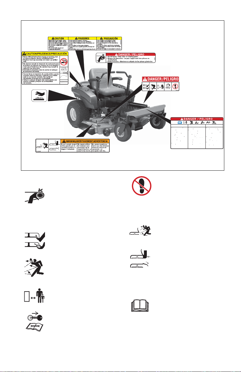
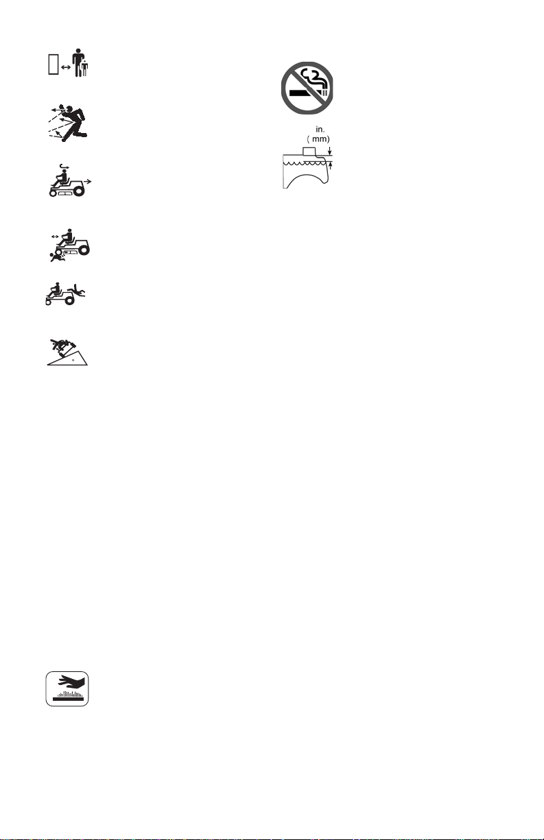
Keep children, people, and pets away. Be
alert and shut off unit if anyone enters work
area. Keep children under watchful care of a
responsible adult.
NEVER allow children to operate or play on
or near unit.
Keep area of operation clear of all toys, and
debris. Thrown objects can cause injury.
Stay alert for hidden hazards, holes, and ruts.
Avoid uneven or rough terrain. DO NOT
operate near drop-offs, ditches, or
embankments. Unit can suddenly turn over if
a wheel is over the edge of a cliff or ditch, or if
an edge caves in.
Dust, fog, etc. can reduce vision and cause
an accident. Operate unit only when there is
good visibility and light.
Data indicates that operators, age 60 and
above, are involved in a larger percentage of
riding mower related injuries. These
operators should evaluate their ability to
operate the riding mower safely enough to
protect themselves and others from serious
injury.
Wear adequate safety gear, sturdy shoes,
and protective gloves.
Only trained adults may operate unit. Training
includes being familiar with controls and
actual operation.
NEVER operate unit after or during the use of
medication, drugs or alcohol.
NEVER allow anyone to operate this unit
when their alertness or coordination is
impaired.
DO NOT wear loose clothing or jewelry and
tie back hair that may get caught in rotating
parts.
Protect eyes, face and head from objects that
may be thrown from unit. Wear appropriate
hearing protection. Always wear safety
goggles or safety glasses with side shields
when operating mower.
Avoid sharp edges. Sharp edges can cut.
Moving parts can cut off fingers or a hand.
ALWAYS keep hands and feet away from all
rotating parts during operation. Rotating parts
can cut off body parts.
ALWAYS keep hands away from all pinch
points.
Start and operate unit only when seated in
operator’s position. Steering control levers
must be in neutral, PTO disengaged and
parking brake set when starting engine.
ALWAYS keep body and hands away from
pin holes or nozzles which eject hydraulic
fluid under pressure.
DO NOT touch unit parts which might be hot
from operation. Allow parts to cool before
attempting to maintain, adjust or service.
NEVER place your hands or any part of your
body or clothing inside or near any moving
part while unit is running.
NEVER direct discharge towards persons or
property. Thrown objects may ricochet back
towards operator. ALWAYS stand clear of the
discharge area.
ALWAYS disengage attachment, stop unit
and engine, remove key, engage parking
brake, and allow moving parts to stop before
leaving operator’s position.
Use extreme caution on gravel surfaces.
Disengage PTO when attachment is not in
use and when crossing gravel surfaces.
DO NOT operate unit if safety interlock
system is damaged or disabled. Check safety
interlock before each use.
ALWAYS remove key to prevent unauthorized
use.
DO NOT operate at too fast a rate. Slow
down before turning.
Stop engine before removing grass catcher or
unclogging chute.
DO NOT mow on wet grass. Reduced
traction could cause sliding.
DO NOT mow with the deck access plate
open. Always make sure the access plate is
down, or secured down, with the hardware.
DO NOT try to stabilize the machine by
putting your foot on the ground.
Know the weight of loads. Limit loads to those
you can safely control and the unit can safely
handle.
ALWAYS keep protective structures, guards
and panels in good repair, in place and
securely fastened.
Do not operate without either entire grass
catcher or the discharge guard in place.
DO NOT operate in reverse unless absolutely
necessary. ALWAYS look down and behind
before and while backing; especially for
children.
Follow the manufacturer’s recommendations
for wheel weights or counterweights to
improve stability when using attachments.
NEVER carry passengers–especially
children–even with blades off.
Use extra care when approaching blind
corners or objects that may obscure vision of
hidden obstacles and children.
If you cannot back up a slope or you feel
uneasy on it, do not mow it.

GB - 8
Mow up and down slopes, not across them.
Use slow speed on any slope. Tires may lose
traction on slopes even though the brakes are
functioning properly.
Keep all movements on the slope slow and
gradual. DO NOT make sudden changes in
speed or direction.
Use extra care while operating machines with
grass catcher or other attachments. They can
affect stability of the machine.
Avoid starting, stopping, or turning on a
slope. If tires lose traction, disengage the
blades and proceed slowly straight down the
slope.
DO NOT operate on slopes over 10°.
DO NOT park on slopes unless necessary. If
unit is parked on a slope, ALWAYS chock or
block wheels and set parking brake.
DO NOT disengage or bypass transmission
and coast downhill.
Tow only with a machine that has a hitch
designed for towing. Do not attach towed
equipment except at the hitch point.
Follow the manufacturer’s recommendations
for weight limits for towed equipment and
towing on slopes.
NEVER allow children or others in or on
towed equipment.
On slopes, the weight of the towed equipment
may cause loss of traction and loss of control.
Travel slowly and allow extra distance to stop.
Use extra care when loading or unloading
unit onto trailer or truck.
Secure unit chassis to transport vehicle.
NEVER secure from rods or linkages that
could be damaged.
DO NOT transport machine while engine is
running.
ALWAYS turn off power to attachment and
shut off fuel when transporting unit.
Keep unit free of grass clippings, leaves, and
other debris. Clean up oil or fuel spills.
This product is equipped with an internal
combustion type engine. DO NOT use unit on
or near any unimproved, forest-covered or
brush covered land unless exhaust system is
equipped with a spark arrester meeting
applicable local, state or federal laws. A spark
arrester, if it is used, must be maintained in
effective working order by operator.
Fuel is highly flammable and its vapors are
explosive. Handle with care. Use an
approved fuel container.
NO smoking, NO sparks, NO flames.
ALWAYS allow engine to cool before
servicing.
NEVER fill fuel tank when engine is running
or hot from operation.
NEVER fill or drain fuel tank indoors.
NEVER overfill fuel tank.
Replace fuel cap securely and clean up
spilled fuel.
NEVER fill containers inside a vehicle or on a
truck or trailer bed with a plastic liner. Always
place containers on the ground away from
your vehicle before filling.
When practical, remove gas-powered
equipment from the truck or trailer and refuel
it on the ground. If this is not possible, then
refuel such equipment on a trailer with a
portable container, rather than from a
gasoline dispenser nozzle.
Keep the nozzle in contact with the rim of the
fuel tank or container opening at all times until
fueling is complete. Do not use a nozzle lock-
open device.
If fuel is spilled on clothing, change clothing
immediately.
Avoid Electric Shock. Objects contacting both
battery terminals at the same time may result
in injury and unit damage. DO NOT reverse
battery connections.
Explosive Gases from battery can cause
death or serious injury. Poisonous battery
fluid contains sulfuric acid and its contact with
skin, eyes or clothing can cause severe
chemical burns.
NO flames, NO sparks, NO smoking near
battery.
ALWAYS wear safety glasses and protective
gear near battery. Use insulated tools.
Battery posts, terminals and related
accessories contain lead and lead
compounds, chemicals known to the State of
California to cause cancer and reproductive
harm. Wash hands after handling.
ALWAYS keep batteries out of reach of
children.
Reverse connections may result in sparks
which can cause serious injury. Always
connect positive (+) lead of charger to
positive (+) terminal, and negative (-) lead to
negative (-) terminal.
ALWAYS disconnect negative (-) cable FIRST
and positive (+) cable SECOND. ALWAYS
connect positive (+) cable FIRST, and
negative (-) cable SECOND.

GB - 9
A frozen battery can explode and result in
death or serious injury. DO NOT charge or
jump start a battery containing frozen fluid.
Thaw the battery before putting on a charger
or jump starting.
ALWAYS keep protective structures, guards,
and panels in good repair, in place and
securely fastened. NEVER modify or remove
safety devices.
DO NOT change engine governor settings or
over-speed engine.
Fumes from engine exhaust can cause injury
or death. DO NOT run engine in an enclosed
area. Always provide good ventilation.
ALWAYS maintain unit in safe operating
condition. Damaged or worn out muffler can
cause fire or explosion.
Stop and inspect equipment if you strike an
object or if there is an unusual vibration.
Repair, if necessary, before restarting. Never
make adjustments or repairs with the engine
running.
Mower blades are sharp and can cut you.
Wrap the blade(s) or wear gloves, and use
extra caution when servicing them. NEVER
weld or straighten mower blades.
Rotation of one blade may cause rotation of
the other blades.
Check brake operation frequently. Adjust and
service as required.
Keep all hardware properly tightened.
Stored energy in springs can cause injury.
Maintain or replace safety and instruction
labels, as necessary.
Never store the machine or fuel container
inside a building where there is an open
flame, such as a water heater.
Shut off fuel (if provided) and allow engine to
cool completely before storing in closed area
or covering unit.
Clean grass and debris from unit, especially
from around muffler and engine, to help
prevent fires.
For extended storage, clean unit thoroughly.
See Engine Manual for proper storage.
Use only attachments or accessories
designed for your unit.
Check attachment components frequently. If
worn or damaged, replace with
manufacturer’s recommended parts.
Tools Required
• Adjustable wrench
• 9/16" wrench
• Petroleum jelly or dielectric grease.
Unpack Unit
Remove unit and all other components from
the shipping container. Engage transmission
bypass lever (see MOVING UNIT
MANUALLY on page 14). Push unit from
container onto a level surface. Disengage
transmission bypass lever.
Connect Battery
See Battery Removal and Installation on
page 19 and perform steps 2 and 3 in the
installation section.
Place Unit in Operating Position
(figure 3):
NOTE: The unit is shipped with the seat
positioned as far back as possible.
1. Tip seat forward and adjust the seat as
needed (see ADJUSTING STEERING
LEVERS on page 20).
2. Remove eccentric spacers and rotate
steering levers to the operating position.
reinstall spacers. Do not tighten.
ASSEMBLY
WARNING: AVOID INJURY. Read
and understand the entire Safety
section before proceeding.

GB - 10
3. Adjust steering levers (see ADJUSTING
STEERING LEVERS on page 20).
Check Engine Oil Level
1. Refer to Engine Manual.
Level Mower Deck
See on page 17.
Fill Fuel Tanks
See FILLING FUEL TANKS on page 13.
Adjust Seat
See Adjusting Seat on page 13.
Check Safety Interlock System
See Safety Interlock System on page 12.
Check function of all controls
See OPERATION on page 12.
Check Tire Pressure
See SERVICE PARTS on page 27.
WARNING: Safety interlock failure
and improper operation of unit can
result in death or serious injury.
Check system before each use to
make sure it is functioning
properly.
Figure 3
2
4
3
1
1. Seat
2. Steering Lever
3. Eccentric
4. Handlebar
Brackets
3
CAUTION: Avoid injury!
Explosive separation of tire and
rim parts is possible when they
are serviced incorrectly:
• Do not attempt to mount a
tire without the proper
equipment and experience
to perform the job.
• Do not inflate the tires above
the recommended pressure.
• Do not weld or heat a wheel
and tire assembly. Heat can
cause an increase in air
pressure resulting in an
explosion. Welding can
structurally weaken or
deform the wheel.
• Do not stand in front or over
the tire assembly when
inflating. Use a clip-on chuck
and extension hose long
enough to allow you to stand
to one side.

GB - 12
CONTROLS AND FEATURES
See figure 4 for all controls and features
locations.
Safety Interlock System
Perform the following tests to ensure the
safety interlock system is working properly. If
the unit does not perform as stated contact
your Ariens dealer for repairs.
Ignition Switch Operate ignition
switch with a
removable key.
Ignition switch has
four positions:
Stop (1), Headlight
(2), Run (3), Start (4).
See STARTING AND
SHUTTING OFF
ENGINE on page 14
for detailed
instructions on how to
start engine.
Throttle Lever Fast (1) – Increases
engine speed.
Slow (2) – Decreases
engine speed.
Choke Control Use to start a cold
engine. Pull choke
control out to choke
engine. Push choke
control in when engine is
warm.
Parking Brake Engages (2) and
disengages (1) parking
brake.
Power Take-Off (PTO) Switch
Engages (2)
anddisengages
(1) mower
blades.
Hour Meter Records total number of
hours engine has been run.
NOTE: Hour meter will
continue to run if ignition key
is left in the run position with
the engine turned off.
OPERATION
WARNING: AVOID INJURY. Read
and understand the entire Safety
section before proceeding.
WARNING: Safety interlock failure
and improper operation of unit can
result in death or serious injury.
Check system before each use to
make sure it is functioning
properly.
Test Steering
Lever PTO Parking
Brake Engine
1 Neutral
Position Off Engaged Starts
2 Neutral
Position On Engaged Doesn’t
Start
3 Neutral
Position Off Disengaged Doesn’t
Start
4*+ Out of
Neutral
Position
Off Disengaged Shuts
Off
5*+ Neutral
Position On Engaged Shuts
Off
* Test with engine running.
+ Operator lifts off seat.
1
2
3
4
1
2
1
2
1
2

GB - 13
Steering Levers
• Reverse (1) – Pull both steering levers
backward.
• Forward (2) – Push both steering levers
forward.
• Left (3) – Pull left steering lever back or
push right steering lever forward or a
combination of both.
• Right (4) – Pull right steering lever back
or push left steering lever forward or a
combination of both.
NOTE: To stop, return both steering levers to
neutral.
NOTE: The steering levers must be in the
neutral position to start the engine.
NOTE: The parking brake must be
disengaged prior to moving the steering
levers from the neutral position.
Mower Lift Pedal (figure 5)
Raises and lowers the deck.
NOTE: The adjustment pin is used to set the
height of the mower deck. See
SPECIFICATIONS on page 28 for cutting
height dimensions.
Press mower lift pedal and install adjustment
pin in the desired adjustment hole.
NOTE: Adjusting the seat
further forward will help
increase the leverage in
lifting the mower deck (see
FILLING FUEL TANKS on
page 13).
Adjusting Seat
Lift adjustment lever and slide seat forward or
backward to the desired position.
FILLING FUEL TANKS
1. Clean fuel caps and surrounding area to
prevent dust, dirt, and debris from
entering fuel tanks.
2. Remove fuel caps.
IMPORTANT: See Engine Manual for correct
type and grade of fuel.
3. Fill fuel tanks to 2-1/2 in. (6.35 cm)
below bottom of filler neck. See
SPECIFICATIONS on page 28 for
capacity of fuel tanks.
4. Replace fuel caps.
12
34
Figure 5
1. Adjustment Pin
2. Mower Lift Pedal
3. Adjustment Hole
132
02988000
7
08088400A
Figure 6
1. Seat
2. Adjustment Lever
12

GB - 14
STOPPING IN AN EMERGENCY
Bring steering levers back to neutral, set
parking brake, and turn off engine.
MOVING UNIT MANUALLY
Disengage (2) transmission bypass levers to
drive unit and engage (1) transmission
bypass levers to push unit manually
(figure 7).
STARTING AND SHUTTING OFF
ENGINE
Starting the Engine
NOTE: Disengage the PTO, engage the
parking brake, and place the steering levers
in neutral prior to starting the engine.
1. If the engine is cold, move the choke
control to the On position. If the engine
is warm or hot, do not use choke.
2. Move the throttle to 1/3 Fast position.
See Engine Manual for detailed
instructions.
IMPORTANT: DO NOT operate starter for
more than 15 seconds per minute as damage
can occur.
3. Turn ignition key to start position and
release once the engine has started.
4. Move the choke control to the Off
position. Wait until the engine is running
smoothly before operation.
IMPORTANT: Let the engine warm up
several seconds to several minutes
depending on outside temperature.
Stopping the Engine
1. Stop unit.
2. Disengage PTO.
3. Set throttle lever to slow.
4. Turn ignition switch to off position and
remove key.
5. Set parking brake.
OPERATING MOWER
1. Start engine.
2. Set throttle lever to fast.
IMPORTANT: Never engage PTO if mower is
plugged with grass or other material.
3. Engage PTO to start mower blades.
NOTE: The parking brake must be
disengaged prior to moving the steering
levers from the neutral lockout position.
4. Release parking brake.
5. Use steering levers to move the unit.
6. Disengage PTO to stop mower blades.
TRANSPORTING UNIT
ALWAYS shut off engine, set parking brake,
remove key, and close fuel shut-off valve or
drain fuel when transporting unit on a truck or
trailer. Tie unit down securely. Do not tie
down by linkages, guards, cables or other
parts that may be damaged.
WARNING: DO NOT disengage
or bypass transmission and coast
downhill.
Figure 7
1. Transmission Bypass Lever Engaged
2. Transmission Bypass Lever
Disengaged
12

GB - 15
FOR BEST PERFORMANCE
Cut grass when it is dry.
Keep mower blades sharp.
Keep mower deck properly leveled.
Adjust anti-scalp rollers to prevent scalping.
Do not set height of cut too low. For very tall
grass, mow twice.
Do not travel too fast.
Mow with the engine set at full throttle.
When mulching, only remove 1/3 of grass
length per cutting.
Discharge clippings into areas already cut.
Vary cutting pattern with each mowing.
Do not allow grass or debris to collect inside
of mower deck. Clean after each use.
IMPORTANT: Proper maintenance can
prolong the life of unit. The following chart
shows the recommended service schedule.
Refer to the maintenance instructions in the
Engine Manual for additional information.
NOTE: To have full access to the engine, the
seat must be tipped forward (see TIPPING
SEAT FORWARD on page 16) and the hood
opened (see OPENING AND CLOSING
HOOD on page 17).
MAINTENANCE SCHEDULE
WARNING: AVOID INJURY. Read
and understand the entire Safety
section before proceeding.
Interval Task Action
Each Use
Check
Safety
Interlock
System
WARNING: Safety interlock system failure and improper
operation of unit can result in death or serious injury. Test
this system each time the unit is operated. If this system
does not function as described, do not operate until repairs
are made (see Safety Interlock System on page 12).
Check
Parking
Brake
Engage parking brake and engage transmission bypass lever (see
MOVING UNIT MANUALLY on page 14). Push unit. If unit rolls,
contact your Ariens Dealer.
Clean Unit Clean engine, battery, seat, mower deck, etc. of all dirt and debris. Do
not use solvents, hard cleaners, or abrasives.
NOTE: Protect painted surfaces with automotive type wax.
See SPECIFICATIONS on page 28 for correct tire pressure.
Check
Tires CAUTION: Avoid injury! Explosive separation of tire and rim
parts is possible when they are serviced incorrectly:
•Do not attempt to mount a tire without the proper equipment
and experience to perform the job.
• Do not inflate the tires above the recommended pressure.
• Do not weld or heat a wheel and tire assembly. Heat can cause
an increase in air pressure resulting in an explosion. Welding can
structurally weaken or deform the wheel.
• Do not stand in front or over the tire assembly when inflating. Use
a clip-on chuck and extension hose long enough to allow you to
stand to one side.
Check
Mower
Blades
CAUTION: Check for worn or damaged mower blades.

GB - 16
TIPPING SEAT FORWARD
Put steering levers up and tip seat forward.
Each Use
Follow
Engine
Manual
Mainten-
ance
Schedule
Perform scheduled engine
maintenance. Refer to
Engine Manual for
detailed instructions.
NOTE: To drain the oil,
use the oil drain
petcock (1) supplied with
unit, not the drain plug that
is shown in the Engine
Manual.
25Hours
or Every
Season
Check
Battery Keep battery and battery terminals clean (see Cleaning Battery and
Battery Cables on page 20).
Lubricate
Unit Apply grease to zerk (1) on each
front wheel
50Hours
or Every
Season
Check
Fasteners Check mower blade mounting hardware and all other fasteners.
Replace fasteners that are missing or damaged. Tighten all nuts and
bolts to the correct torque value.
100
Hours or
Every
Season
Check All
Belts Replace worn or deteriorated belts.
• Check hydrostatic belt (see REPLACING HYDROSTATIC BELT
on page 22 for hydrostatic belt location).
• Check PTO belt (see REPLACING PTO BELT on page 21 for
PTO belt location).
Interval Task Action
1
1
SERVICE AND ADJUSTMENTS
WARNING: AVOID INJURY. Read
and understand the entire Safety
section before proceeding.
Figure 8
1. Seat Tipped Forward 1

GB - 17
OPENING AND CLOSING HOOD
To open, pull up on the back of the hood until
hood hits the hood stop and push down on
back of hood to close (figure 9).
OPENING DECK ACCESS PLATE
1. Install adjustment pin in the first
adjustment hole (figure 10).
2. Put parking brake on.
3. Raise deck access plate.
REPLACING MOWER BLADE
Remove (Figure 11)
1. Block mower blades to prevent rotation.
2. Remove mounting hardware and mower
blades from mower deck.
Install (Figure 11)
1. Install mower blades on mower deck
with mounting hardware.
2. Torque 5/8-inch hex bolt to 80 to
120 lbf-ft (108 to 163 N•m)
Hood tipped open.
Figure 9
Figure 10
1. Adjustment Pin
2. Deck Access plate
1
2
CAUTION: Mower blades are
sharp and can cut you. Wrap the
blades or wear gloves, and use
extra caution when servicing them.
Figure 11
1. Flat Washer
2. Bevel Washer
3. 5/8-inch Hex Bolt
4. Mower Blade
4
1
2
3

GB - 18
LEVELLING AND ADJUSTING
PITCH OF MOWER DECK
NOTE: Adjust on a level surface, with the
tires inflated to the correct air pressure (see
SPECIFICATIONS on page 28).
There are three measurements required to
level and adjust the pitch of the mower deck.
1. The distance from the mower blades to
the ground.
2. The forward pitch of the mower blades.
3. The pitch of the mower blades from
side-to-side.
The Distance From The Mower
Blades To The Ground (Figure 12):
• In the lowest cutting position should be
1-1/2 in. + 1/4 in. (3.8 cm + 0.64 cm).
• In the highest cutting position should be
4-1/2 in. + 1/4 in. (11.4 cm + 0.64 cm).
The Forward Pitch Of The Mower
Blades (Figure 13):
• Should be 0.0 in. (0.0 mm) to 1/4 in.
(6.35 mm) pitched forward.
NOTE: This measurement must be taken
when the mower blades ends are facing
forward.
The Pitch Of The Mower Blades From
Side-To-Side (Figure 14):
• Should be within 1/4 in. (6.35 mm) as
measured on each side of the mower
deck.
NOTE: This measurement must be taken
when the mower blades ends are
perpendicular (at a right angle) to the frame
of the unit.
Figure 12
Lowest Cutting Position
1-1/2 in. + 1/4 in. (3.8 cm + 0.64 cm)
Highest Cutting Position
4-1/2 in. + 1/4 in. (11.4 cm + 0.64 cm)
13 2
13 2
1. Mower Deck
2. Mower Blade
3. Ground
Forward Pitch of Mower Blades
Forward Pitch = 0.0 in. (0.0 mm) to 1/4
in. (6.35 mm)
Front of Mower
Deck
1
32
Figure 13
1. Mower Deck
2. Mower Blade
3. Ground
1
32
Side-To-Side Pitch
1/4-in. (6.35 cm) from Side-To-Side
Figure 14
1. Mower Deck
2. Mower Blade
3. Ground

GB - 19
Adjusting The Mower Deck To Adjust
Mower Blade Height And Pitch
(Figure 16):
NOTE: Adjusting the mower deck will adjust
the height and pitch of the mower blades.
1. Adjust the trunnions first and re-take the
three measurements required to level
and adjust the pitch of the mower deck.
These measurements are:
a. The distance from the mower
blades to the ground.
b. The forward pitch of the mower
blades.
c. The pitch of the mower blades
from side-to-side.
2. Repeat step 1 as needed until all three
measurements are within the tolerances
specified.
SERVICING BATTERY
NOTE: Unit comes equipped with a
maintenance-free battery that requires no
regular maintenance except cleaning the
terminals and periodic charging.
Battery Removal and Installation
Remove (Figure 17)
1. Tip seat forward (see TIPPING SEAT
FORWARD on page 16).
2. Disconnect negative (–) cable first, then
positive (+) cable.
3. Remove battery hold-down bracket and
battery from unit.
Figure 15
1
1. Rear Trunnion
2. PTO Belt
3. Mower Deck
4. Drag Link
5. Front Trunnion
6. Lift Arm
23546
WARNING: Battery posts,
terminals and related accessories
contain lead and lead compounds,
chemicals known to the State of
California to cause cancer and
reproductive harm. Wash hands
after handling.
Figure 16
1. Trunnion
2. Mower Deck
1
2

GB - 20
Install (Figure 17)
1. Install battery on the unit with battery
hold-down bracket.
2. Connect positive (+) cable first, then
negative (–) cable.
3. Apply petroleum jelly or dielectric grease
to battery cable ends and terminals.
4. Tip seat back (see TIPPING SEAT
FORWARD on page 16).
Cleaning Battery and Battery Cables
(Figure 17)
1. Tip seat forward (see TIPPING SEAT
FORWARD on page 16).
2. Disconnect negative (–) cable first, then
positive (+) cable.
3. Clean battery cable ends, negative (–)
terminal, and positive (+) terminal with a
wire brush and rinse with a weak baking
soda solution.
4. Connect positive (+) cable first, then
negative (–) cable.
5. Apply petroleum jelly or dielectric grease
to battery cable ends and terminals.
6. Tip seat back (see TIPPING SEAT
FORWARD on page 16).
Charging the Battery
(Figure 17)
Follow First Aid directions for contact with
battery fluid.
• External Contact: Flush with water.
• Eyes: Flush with water for at least 15
minutes and get medical attention
immediately!
• Internal Contact: Drink large quantities
of water. Follow with Milk of Magnesia,
beaten egg or vegetable oil. Get medical
attention immediately!
• In case of internal contact, DO NOT
induce vomiting!
IMPORTANT: DO NOT fast charge. Charging
at a higher rate will damage or destroy
battery.
IMPORTANT: ALWAYS follow information
provided on battery and battery charger.
Contact battery and battery charger
manufacturers’ for detailed instructions.
1. Remove battery from unit (see Battery
Removal and Installation on page 19).
2. Place battery in a well-ventilated area.
3. Connect positive (+) lead of charger to
positive (+) terminal, and negative (–)
lead of charger to negative (–) terminal.
4. Charge battery according to battery
charger and battery manufacturers’
instructions.
5. Install battery on unit (see Battery
Removal and Installation on page 19).
Jump-Starting
Ariens does not recommend jump-starting
your unit. Jump-starting can damage engine
and electrical system components. See your
engine manual for more detailed information.
ADJUSTING STEERING LEVERS
Adjusting Steering Lever Height
(Figure 18)
NOTE: Perform steps 1 and 2 for both
steering levers.
1. Remove mounting hardware and move
handlebar up or down until the steering
levers are at the appropriate height.
2. Install mounting hardware.
Figure 17
1. Battery Hold-Down Bracket
2. Negative (–) Cable
3. Negative (–) Terminal
4. Battery
5. Positive (+) Terminal
6. Positive (+) cable
1
5
2
4
6
3
WARNING:FROZEN BATTERIES
CAN EXPLODE and result in
death or serious injury. DO NOT
charge a frozen battery. Let the
battery thaw before charging.
This manual suits for next models
1
Table of contents
Other Ariens Cutter manuals
Popular Cutter manuals by other brands

Grizzly
Grizzly MINI SHEET METAL CUTTER INSTRUCTION SHEET... instruction sheet

EINHELL
EINHELL TH-MA 1300 Original operating instructions

Silca
Silca FUTURA PRO quick start guide

Genesis
Genesis Rail Breaker Safety & operator manual

Martor
Martor SECUNORM 380 Series manual

Swisher
Swisher RTB18552 owner's manual