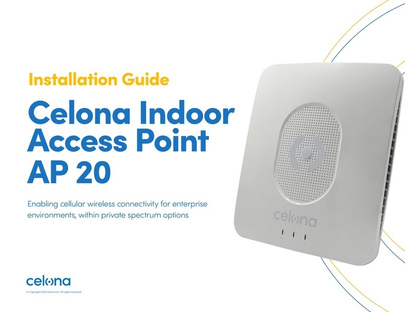
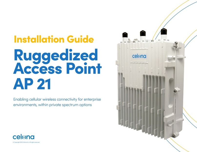
Celona AP 13 User manual

Installation Guide
Celona Medium
Power Access
Point AP 13
© Copyright 2023 Celona Inc. All rights reserved.

© Copyright 2023 Celona Inc. All rights reserved.
Installation Guide Celona Medium Power Access Point AP 13 2
Contents
Introduction 3
About the AP 3 Installation Instructions 3
Installation Preparation 4
Installation Overview 4
Personnel 4
Network Design Plan 4
Materials and Tools 4
Interfaces 4
LEDs 5
Ethernet ports 5
Power input 5
GPS 6
Location and Environment 6
Environmental Specifications 6
Installation 7
Process Overview 7
Pole Installation 7
Wall Installation 9
Connect Cables 10
Connect Ethernet Cable 10
Connect Ground Cable 10
Power on to Check LEDs 11
Checking AP Status 11
Certified Professional Installation 11
Regulatory Compliance 11
Solution Architecture 12
Celona AP 13 capabilities 12 Access Point Discovery and Provisioning 12 Configuring the Access Point 12
Operations and Maintenance 13
Security 13
Phase and time synchronisation 13
Data and voice connectivity 13
Radio access technology 14
Supported frequency band 14
Seamless session mobility 14
Coverage area 14
Transmit power 14
Supported system bandwidth 15
Troubleshooting 16
Contacting Support 16 Warranty 16

© Copyright 2023 Celona Inc. All rights reserved.
Installation Guide Celona Medium Power Access Point AP 13 3
Introduction
This document provides the necessary guidance to
help the user enable services on the Celona Indoor
/ Outdoor Access Point AP 13 capable of private 4G
connectivity. This guide provides an overview of the AP
capabilities and the installation procedures that must
be accompanied.
About the AP
Celona AP 13 is a 3GPP Release 15 compliant 4G Access
Point (AP) with internal antenna that supports the 3550
– 3700 MHz Citizens Broadband Radio Service (CBRS)
spectrum band. It includes two internal radios that
support 2x2 MIMO (multiple-input, multiple-output),
64-QAM modulation, and carrier aggregation (CA). It
can be pole or wall mounted.
Installation Instructions
Ensure the packaging is not damaged or wet. If it is, or
if any items inside are missing or damaged, contact
below contains the shipping list showing the quantity of
each item that should be received.
Item Qty Description
AP 13 unit 1Confirm tag on the unit to ensure received model is correct
PoE injector 1
PoE injector and PoE cable
Installation bracket
assembled kit 1
Assembled kit:
Installation bracket (x1)
Omega (x4)
M10 * 160 outer hex bolt (x4)
M10 flat gasket (x4)
M10 spring gasket (x4)
M10 nut (x4)
Unassembled / Individual kit: M10 flat gasket (x6)
M10 spring gasket (x6)
M10 nut (x6)
M8 (x80)
expansion bolt (x2)
OT Ground Terminal 2For ground cabling

© Copyright 2023 Celona Inc. All rights reserved.
Installation Guide Celona Medium Power Access Point AP 13 4
Installation Overview
The Celona AP 13 can be pole or wall mounted and has one integrated
4-port 13.5 dBi 65D antenna. Before you mount and deploy your access
point, we recommend that you perform a wireless design to determine the
best location to install your access point.
The AP requires an operational Celona Edge for discovery and network
service. Celona recommends installation and deployment of the Celona
Edge prior to installation of access points. Have the following information
about your wireless network design available:
• Locations for access point installation
• Mounting requirements for each location
Installing the access point involves the following steps:
1. Mounting and Powering the Access Point
2. Access Point Discovery and Provisioning
3. Configuring the Access Point
Personnel
Celona recommends that installation personnel review this entire installation
guide prior to beginning the installation. Please note that installing the AP
on a cell tower, building, or other structure may require at least two people
or a qualified tower crew. Installation personnel must follow standard safety
precautions concerning height, electricity, and other regulations.
Network Design Plan
Each cell site may be unique in terms of the type and number of components
to install, the coverage area, the user requirements, and so forth. Identify the
structure on which the AP equipment will be installed, the intended height
where the antenna and AP will be attached, the degree of antenna down
tilt, and other necessary specifications that may impact the success of the
installation.
Materials and Tools
Tables that follow describe the materials required during the installation.
The total output EIRP (Equivalent Isotropic Radiated Power) is governed by
Part 96 regulations of FCC and hence power is automatically calculated and
regulated by Celona software.
Item Description
Power cable < AWG16, e.g., AWG14
Power plug The plug that connects the power cable to
the electricity supply
Ethernet cable CAT6 rated for outdoor use
Ground cable Shorter than 330 feet (100 meters)
Interfaces
Interface Name Description
ETH/POE+
RJ-45 interface (FE/GE)
Used for power supply, debug or data
backhaul.
PoE++, complies with IEEE 802.3bt standard
Installation Preparation

© Copyright 2023 Celona Inc. All rights reserved.
Installation Guide Celona Medium Power Access Point AP 13 5
Installation Preparation
LEDs
The Celona AP 13 has 4 LEDs providing the following visual statuses for Power,
Cellular status (1 and 2), Alarm.
LED Color Status Description
PWR Green
Steady on Power is on
OFF No power supply
CELL1 Green
OFF CELL1 is inactive
Fast flash: 0.1 s on, 0.1 s o CELL1 is deactivated
Slow flash: 1 s on, 1 s o CELL1 is activated
CELL2 Green
OFF CELL2 is inactive
Fast flash: 0.1 s on, 0.1 s o CELL2 is deactivated
Slow flash: 1 s on, 1 s o CELL2 is activated
ALM Red
Steady on Hardware alarm
OFF No alarm
Ethernet ports
The Celona AP 13 has one 100/1000 Ethernet port.
Power input
In addition to AC power, the Celona AP 13 supports IEEE 802.3bt (POE++) connectivity
to drive internal circuitry. POE++ can be provided by a POE++ injector or a POE++
capable switch. The drawn power is ≤ 30 W.

© Copyright 2023 Celona Inc. All rights reserved.
Installation Guide Celona Medium Power Access Point AP 13 6
Installation Preparation
GPS
Built-in GPS synchronization for AP 13.
Location and Environment
When determining where to place the AP, you need to consider
factors such as climate, hydrology, geology, the possibility of
earthquakes, reliable electric power, and transportation access.
Avoid locating the AP in areas where there may be extreme
temperatures, harmful gases, unstable voltages, volatile vibrations,
flames, explosives, or electromagnetic interference (e.g., large radar
stations, transformer substations). The AP is not certified for HAZLOC
installation. Also, avoid areas that are prone to impounded water,
soaks, leakage, or condensation.
Environmental Specifications
Item Description
Operating Temperature -40°F to 131°F / -40°C to 55°C
Storage Temperature -49°F to 158°F / -45°C to 70°C
Humidity 5% to 95% RH
Atmospheric Pressure 70 kPa to 106 kPa
Safety voltage 42 V to 58 V

© Copyright 2023 Celona Inc. All rights reserved.
Installation Guide Celona Medium Power Access Point AP 13 7
Installation
Some cell site structures may have existing frameworks for
attaching the AP. For purposes of explaining the installation
procedure, this section assumes the AP will be installed on a
support pole or on a wall.
Process Overview
Figure below provides an overview of the installation process.
• Installation Process Overview
• Install AP to the pole (or wall)
• Connect the Ethernet and ground cables
• Power on device
• Check LEDs
Pole Installation
Check to ensure the diameter of the pole is in the range of
1.6-2.8 inches (40-70 mm). The position of the AP on the pole
should be at least 47 inches (120 cm) in height.
The AP 13 mounting bracket is assembled
before packing and includes two components:
the preassembled bracket on the back of the
device and the pole or wall mounting bracket.
gNB
Pole
1.6 in.–3.9 in.
(40mm–100mm)
47 in.
(120 cm)
Pole or Wall Mounting Bracket

© Copyright 2023 Celona Inc. All rights reserved.
Installation Guide Celona Medium Power Access Point AP 13 8
Installation
Follow the steps below to install the AP 13 on a pole.
1. Unscrew the nuts of the pole mounting bracket, slide the
two clamps to the left, and turn them up or down
2. Place the pole mounting bracket against the pole and
return the clamps to the horizontal position. Slide the
clamp to the right and retighten the nuts.
4. Tighten the bolt and screw
on the top of the AP 13 with a
Phillips-head screwdriver.
5. Once the installation is complete, proceed to “Connect Cables” section.
3. Hold the AP 13 vertically and
align the two pins on the AP
13 bracket with the pin holes
on the pole mounting bracket.
Push the AP 13 down until the
hooks are firmly attached to
the corresponding slots on the
pole mounting bracket.

© Copyright 2023 Celona Inc. All rights reserved.
Installation Guide Celona Medium Power Access Point AP 13 9
Installation
Wall Installation
Ensure the wall can bear at least four times the weight of
the AP 13. The wall mounting bracket is shown below.
Follow the steps below to install the AP 13 on a wall.
1. Place the wall mounting bracket on the wall with
arrow point up and mark the drilling location using
a pencil or marker.
2. Drill two 0.4 in. (10 mm)
diameter by 2.8 in. (70 mm)
deep holes in the wall at the
marked locations and insert
expansion bolts.
3. Hang the wall mounting
bracket on the expansion bolts
and fasten it with flat washers,
spring washers, and nuts.
5. Once the installation is complete, proceed to the “Connect Cables” section.
4. Hold the AP 13 vertically and align the two pins
on the AP 13 bracket with the pin holes on the pole
mounting bracket. Push the AP 13 down until them
hooks are firmly attached to the corresponding
slots on the pole mounting bracket. Then, tighten
the screw to complete the installation.

© Copyright 2023 Celona Inc. All rights reserved.
Installation Guide Celona Medium Power Access Point AP 13 10
Connect Cables
General requirements:
• Bending radius of antenna feeder cable: 7/8” > 250mm, 4/5” > 380mm
• Bending radius of jumper cable: 1/4” > 35mm, 1/2” (super soft) > 50mm,
1/2” (ordinary) > 127mm
• Bending radius of power cable and grounding cable: > triple the diameter
of the cable
Bind the cables according the type of the cable; intertwining and crossing
are performance impacting and hence forbidden. An identification label
should be attached after the cable is laid for cataloguing and referencing.
Grounding cable requirement:
• The grounding cable must connect to the grounding point.
• The grounding cable must be separated from the signal cables with
sucient distance to avoid signal interference.
Connect Ethernet Cable
• Connect the Ethernet cable to the ETH interface in the wiring cavity. Lay
the Ethernet cable along the wire groove and stretch it out of the wiring
cavity from the ETH hole.
• The Ethernet cable connects to the PoE interface of the PoE adapter. The
PoE adaptor must be placed in the distribution box for waterproofing.
• The LAN interface of the PoE adaptor connects to a LAN switch or a router
for maintenance and backhaul.
Connect Ground Cable
Prepare the grounding cable according to the actual measurements and
requirements of the specific installation site. The AP 13 has two grounding
screws located on the bottom of the unit as shown below.
Unscrew one grounding screw, connect one end of the ground cable to the
grounding screw, and fasten it again. The other end of the ground cable
needs to connect to a good grounding point.
When the AP has been installed in a proper position, connect all the cables
and wires. Seal and weatherproof all the connections after the testing have
been successfully completed.
Installation

© Copyright 2023 Celona Inc. All rights reserved.
Installation Guide Celona Medium Power Access Point AP 13 11
Installation
Power on to Check LEDs
Power on the AP and check that the LED indicators are lighting as expected. Refer
to the LED descriptions detailed in earlier sections of this document.
Checking AP Status
The Celona AP 13 is designed to be plug-and-play, and therefore arrive pre-
configured. The status is inferred by the LEDs and subsequently by connecting a
mobile device to the Celona AP. A properly connected AP will show the Celona logo
as the operator on the mobile’s screen.
Certified Professional Installation
The Celona AP 13 is a Class-B, FCC Part 96 certified device. Class-B devices are
required to be professionally installed by a Certified Professional Installer (CPI).
The CPI is a FCC approved personnel and has legal authority to validate and
confirm the installation with a digital signature.
The following information must be entered for each AP 13 by the CPI and the
information must be signed o by a CPI with current standing.
• GPS coordinates: Latitude, Longitude, Height, Height Type (either a value above
sea level or a value above ground level)
• Antenna details: Antenna Azimuth, Antenna Downtilt, Antenna Gain, Eirp
Capability (Conductive power), Antenna Beamwidth, Antenna Model
The CPI information detailed above is packaged alongside the AP’s FCC ID, the
operator’s ID (user ID) and signed with CPI’s private key.
The CPI ensures the above values are verified for each AP and signs o the CPI
data with the, CPI Identification, CPI Name and Certified Installation time.
The CPI information is securely uploaded per AP to the Celona Orchestrator over
a HTTPs interface. Celona Edge uses the information for each AP when it registers
the APs with the Spectrum Manager.
Regulatory Compliance
FCC Compliance
This device complies with part 15 of the FCC Rules. Operation is subject to the
following two conditions: (1) This device may not cause harmful interference, and
(2) this device must accept any interference received, including interference that
may cause undesired operation. Any Changes or modifications not expressly
approved by the party responsible for compliance could void the user's authority
to operate the equipment.
This equipment has been tested and found to comply with the limits for a Class
B digital device, pursuant to part 15 of the FCC Rules. These limits are designed
to provide reasonable protection against harmful interference in a residential
installation. This equipment generates, uses, and can radiate radio frequency
energy and, if not installed and used in accordance with the instructions, may
cause harmful interference to radio communications.
Warning: This equipment complies with FCC radiation exposure limits set
forth for an uncontrolled environment. This equipment should be installed
and operated with minimum distance 12 inches (30 cm) between the
radiator & your body.

© Copyright 2023 Celona Inc. All rights reserved.
Installation Guide Celona Medium Power Access Point AP 13 12
The system consists of the essential functions detailed in Figure
1: System Architecture. The Celona Orchestrator performs AP
authentication, validates the AP’s serial number, determines the
network the AP needs to connect to and finally directs the Celona
AP 13 to the serving Celona Edge.
Each Celona AP 13 obtains service via its serving Celona Edge. The
Celona Edge registers the Celona AP 13, arbitrates spectrum with a
FCC approved Spectrum Access Service (SAS) system in the United
States and algorithmically determines the most optimal radio
parameters for the AP.
The Celona Edge becomes automatically aware of the Celona AP
13’s location and its existing surrounding radio environment. Once
the AP is admitted by the Celona Edge, the AP is able to commence
radio transmissions and service the mobile stations.
Solution Architecture
The high level architecture that enables the Celona AP 13 is shown below.
Celona
Orchestrator
Spectrum
Manager
Celona Edge
Packet
Data Network
Voice
& Multimedia
Network
Celona AP
SSL
SSL SSL
SSL
IPSEC
IPSEC
Figure 1

© Copyright 2023 Celona Inc. All rights reserved.
Installation Guide Celona Medium Power Access Point AP 13 13
Celona AP 13 capabilities
This following sections give the reader the capabilities of the Celona Indoor Access
Point (AP), which is based on the Qualcomm platform. The AP hosts functions to
provide the following services:
• Resource management with admission and flow control
• Encryption of user data and control streams
• Registering mobile stations with Celona Edge for connectivity services
• Paging the mobile stations that are in power save mode
• Fairness in allocation of resources across multiple stations in uplink & downlink
directions
• Measurement configurations and handling of mobility of mobile stations
Access Point Discovery and Provisioning
The AP will connect to the Celona Orchestrator for provisioning and discover the
Celona Edge within the network on-premises or in the private/public cloud based
on the site assignment. The AP will then connect directly to the Celona Edge and
establish control and data plane connections. Once this is completed, the 4G LED
on the AP will turn blue, signifying the private 4G network is operational. This will
take approximately 2-3 minutes.
Configuring the Access Point
The Celona AP 13 supports zero-touch provisioning. The AP is preconfigured
with details necessary to discover the Celona Orchestrator and the Celona Edge
automatically. After the AP discovers the Celona Orchestrator and the Celona
Edge, the AP gets provisioned with operational parameters and is authorised to
transmit. The Celona Edge alone controls the radio frequency transmission of the
Celona AP 13.
Once the AP has gone operational, it will be able to provide services to mobile
stations. The mobile stations can interact with the enterprise network via the
Celona Edge. The user data and control signals are encrypted. The Celona AP
13 performance is periodically monitored by the Celona Edge and operational
parameters are continually optimised if necessary. Refer to the Celona
Orchestrator configuration guide for detailed instructions on configuring Celona
access points.
Solution Architecture

© Copyright 2023 Celona Inc. All rights reserved.
Installation Guide Celona Medium Power Access Point AP 13 14
The Celona AP 13 is operationally maintained by the Celona Orchestrator and
Celona Edge using NETCONF. Celona AP 13’s radio parameter provisioning,
performance monitoring and fault monitoring occur over the NETCONF interface.
The AP supports the following technical reports from the Broadband Forum
Fault management TR-157 Ammendment 5
Celona AP 13’s performance is monitored between every 5 minutes and 15 minutes
based on the periodicity determined by the Celona Edge. If a fault surfaces on the
AP, the fault is automatically propagated by the AP to the Celona Edge and the
Celona Orchestrator.
Security
The Celona AP 13’s interfaces are secured by IPSEC or SSL. The certificates
required to establish HTTPs connections with the Celona Orchestrator and IPSEC
with the Celona Edge are provisioned at the factory.
If the certificates on the Celona AP 13 need to be updated or replaced, the process
is automatically triggered and managed by the Celona Edge. The certificates
conform to the industry compliant X.509 standard.
The IPSEC gateway is provisioned within the Celona AP 13 through the Celona
Orchestrator. IKEv2 is used to establish the IPSEC tunnel between the Celona AP 13
and Celona Edge.
Phase and time synchronisation
Celona AP 13 supports Time Division Duplex (TDD) which has strict requirements
for maintaining time and phase synchronisation so that it does not interfere with
neighbouring APs. The Celona AP 13s have a built in, high fidelity GPS chip that can
establish location as well as maintaing clock synchronisation.
The AP’s carrier frequency accuracy, time and phase drifts are disciplined by the
onboard GPS clock. If the AP cannot obtain a GPS lock for any reason, Celona AP
13 synchronises with a Precision Time Protocol (PTP) server to maintain time, phase
and frequency synchronisation.
Operations and Maintenance

© Copyright 2023 Celona Inc. All rights reserved.
Installation Guide Celona Medium Power Access Point AP 13 15
Celona Edge
Celona Edge
Packet
Data Network for
data Sercices
IP Multimedia subsystem
for Voice & Video
telephony services
Celona AP
Celona AP
Data Services
Voice & Video
Telephony services
IPSECIPSEC
IPSECIPSEC
Operations and Maintenance
Data and voice connectivity
As seen in figure 2, mobile stations can
obtain data and/or voice connectivity via the
Celona Edge after the Celona AP 13 has its
radio enabled. Celona AP 13 automatically
determines the capability of mobile stations
before determining whether requested
services can be accommodated.
Celona AP 13 and Celona Edge perform
admission control for the mobile station
and Celona Edge enforces authentication
of the mobile station before accepting
service requests. Further, Celona Edge
and Celona AP 13 encrypt all control signals
and user data between the mobile station
and the Celona Edge.
Celona AP 13 employs sophisticated adaptive
modulation & code rate control for adapting
mobile stations’ link according to the dynamic
channel conditions seen on the air interface
between the mobile stations and Celona AP
13. Celona AP 13 also employs eective power
control to keep transmit powers from the
mobile stations as low as practicable.
Figure 2

© Copyright 2023 Celona Inc. All rights reserved.
Installation Guide Celona Medium Power Access Point AP 13 16
Radio access technology
Celona AP 13 implements an extensive set of 3GPP world-wide standards to
provide advanced, 4th generation packet radio service to mobile stations.
AP radio access
technology Technical specifications
Advanced 4th
generation (4G)
Long Term Evolution
(4G-Advanced)
All relevant Release 12 specifications from 3GPP
36.331 Release 12 – Radio Resource Control
36.321 Release 12 – Media Access Control
36.322 Release 12 – Radio Link Control
36.323 Release 12 – Packet Data Convergence
36.413 Release 12 – S1 Application interface
36.423 Release 12 – X2 Application interface
29.274 Release 12 – eGTP control plane
29.281 Release 12 – eGTP user plane
36.211 Release 12 – Physical channels and
modulation
36.212 Release 12 – Physical chanel multiplexing and
coding
36.213 Release 12 – Physical layer procedures
36.214 Release 12 – Physical layer measurements
Supported frequency band
Celona AP 13 supports frequency ranges from 3400 MHz to 3800 MHz. The
operational frequencies are however limited to a narrower range, from 3550
MHz to 3700 MHz, which is commonly labeled as the CBRS spectrum in the United
States or the 4G Band 48. Any Celona AP 13 within a Celona private 4G network
is automatically assigned frequency and power levels by Celona’s unique Self
Organizing Network (SON) software function, after the Celona Edge retrieves
available frequency channels per AP from SAS, given each AP’s geo-location.
Seamless session mobility
If there are multiple Celona AP 13s in the system all connecting to the same Celona
Edge, the Celona AP 13s can enable seamless mobility for mobile stations. The
source and target Celona AP 13s handle the transfer of contextual information
corresponding to existing flows set up for the mobile station automatically.
Coverage area
The coverage area of each Celona AP 13 depends on a number of factors:
• Transmit power authorized by the Spectrum Manager
• Transmit power set on the Celona AP 13 by Celona Edge
• Number of other APs operating on the same frequency in the geographic area
• Proximity of other APs operating on a dierent frequency but in the same band
• Building type and material types used within the building
• Expected minimum for data rate at the edge of coverage
Transmit power
The Celona AP 13 can transmit at a maximum power of 1 Watt per channel inclusive
of internal gain.
Operations and Maintenance

© Copyright 2023 Celona Inc. All rights reserved.
Installation Guide Celona Medium Power Access Point AP 13 17
Supported system bandwidth
The Celona AP 13 supports two concurrent RF chains. The two RF chains provide
two distinct cellular sectors. The following combinations of system bandwidth are
possible depending on authorisation provided by the Spectrum Manager.
Sector 1 Sector 2 Aggregated bandwidth (one AP)
20 MHz 20 MHz 40 MHz
10 MHz 10 MHz 20 MHz
5 MHz 5 MHz 10 MHz
20 MHz -20 MHz
10 MHz -10 MHz
5 MHz -5 MHz
The AP 13 is a dual carrier eNodeB and is based on 4G Release 15. When the
antenna configuration is arranged in such a way that overlapping coverage of two
orthogonal carriers exists, the AP supports two-component carrier aggregation
(CCA). CCA provides the ability to take two component carriers and bond them into
one, thus allowing an eective doubling of achievable data rate. Each component
carrier can be as wide as 20 MHz and hence, CCA provides an aggregated
bandwidth of up to 40 MHz.
The AP has ability to aggregate any two channels from across the full Citizens
Broadband Radio System (CBRS) range, even channels that are not adjacent.
Operations and Maintenance
Power LED is not green:
• Ensure the AP 13 has a POE++ (802.3bt) connection.
• Please check for loose connections between the POE++ injector / POE++ switch
and the Celona AP 13.
Contacting Support
Warranty
As part of an active Celona subscription, Celona AP 13s come with a limited
warranty that includes advanced replacement for RMA.
Troubleshooting

© Copyright 2023 Celona Inc. All rights reserved.
Installation Guide Celona Medium Power Access Point AP 13 18
900 E Hamilton Ave Suite 200,
Campbell, CA 95008, United States
celona.io
© Copyright 2023 Celona Inc. All rights reserved.
Table of contents
Other Celona Wireless Access Point manuals
Popular Wireless Access Point manuals by other brands

Allied Telesis
Allied Telesis AT-AP500 installation guide

Aruba
Aruba 387 Series installation guide

Ruckus Wireless
Ruckus Wireless ZoneFlex 7372-E Quick setup guide

Atlantis Land
Atlantis Land I-Fly A02-WAP-54G/G2 quick start guide

KEYA
KEYA TRONIC MIFARE manual

Ubiquiti
Ubiquiti PowerBeam AC PBE-5AC-300 quick start guide

Grandstream Networks
Grandstream Networks GWN76 Series user manual

Brocade Communications Systems
Brocade Communications Systems 300 Quick installation guide

Sophos
Sophos APX 120 operating instructions

Redline Communications
Redline Communications AN-30e user manual

IgniteNet
IgniteNet Spark AC750 quick start guide

Ruijie
Ruijie RG-AP110-L manual